- 1Department of Physics, Stevens Institute of Technology, Hoboken, NJ, United States
- 2NASA Langley Research Center, Hampton, VA, United States
- 3NOAA, Center for Satellite Applications and Research, College Park, MD, United States
- 4NASA Goddard Space Flight Center, Greenbelt, MD, United States
- 5Spectral Sciences, Burlington, MA, United States
- 6Air Force Research Laboratory, Albuquerque, NM, United States
We present an overview and several important upgrades to the Vector Discrete Ordinate Radiative Transfer (VDISORT) code. VDISORT is a polarized (vector) radiative transfer code that can be applied to a wide range of research problems including the Earth’s atmosphere and ocean system. First, a solution is developed to the complex algebraic eigenvalue problem resulting when the b2 component of the Stokes scattering matrix is non-zero. This solution is needed to compute the V component of the Stokes vector
1 Introduction
This paper documents a state-of-the-art numerical code called VDISORT for monochromatic polarized radiative transfer in non-isothermal, vertically inhomogeneous, but horizontally homogeneous media. The physical processes included are Planckian thermal emission, scattering with a general phase matrix, absorption, and surface reflection. The system may be driven by parallel or isotropic unpolarized or polarized radiation incident at the boundaries, as well as by internal thermal sources and thermal emission from the boundaries. The Stokes vector is returned at user-specified angles and levels. The azimuthally-averaged Stokes components are also available. Irradiances and mean radiances can be generated from the azimuthally-averaged radiance, i.e., the first component of the Stokes vector [I,Q,U,V]T.
VDISORT is based on articles published in the open literature, but its theoretical background and algorithmic developments have not been systematically described in one single document. This paper provides an up-to-date complete description of VDISORT including a self-contained account of its theoretical basis and a discussion of the numerical implementation of the theory.
Like DISORT, the scalar version, VDISORT has been designed to be a good scientific software package and a numerical code of general utility. The VDISORT package takes advantage of robust existing software tools to make it numerically well-conditioned, and user-friendly. A set of test cases have been adopted to verify the numerical code against published results.
1.1 Outline of Paper
This paper is organized as follows. Section 1 provides the motivation for and a brief history of VDISORT, while Section 2 provides theoretical background, introduces the radiative transfer equation for unpolarized and polarized radiation, and discusses the inherent optical properties including the phase matrix. The solution of the vector radiative transfer equation (VRTE) is discussed in Section 3 including the discrete ordinate method, important upgrades of the vector discrete ordinate code (VDISORT), the ISF method, and treatment of polarized reflectance from the lower boundary. Section 4 discusses the merits of the 4 × 4 solution versus the 3 × 3 approximation, while Section 5 is devoted to the single-scattering approximation, which is used in a post-processing step to enhance the accuracy of the computed results for a given number of discrete ordinate streams. Test results are presented in Section 6 including comparisons with published benchmarks. Finally, in Section 7 a brief summary and concluding remarks are provided.
1.2 Brief History
The discrete ordinate radiative transfer algorithm (DISORT) has proven to be an accurate, versatile and reliable method for the solution of the scalar radiative transfer problem in plane-parallel, vertically inhomogeneous media (Stamnes et al., 1988; Lin et al., 2015; Laszlo et al., 2016; Stamnes K. et al., 2017). An extension of the scalar discrete ordinate theory to solve for the complete Stokes vector I = [I,Q,U,V]T was reported by Weng (1992), who adopted an approach to the solution of the vector problem completely analogous to the scalar case. Hence, the computer code for the vector problem, VDISORT, could rely on the same well-tested routine to obtain the eigenvalues and eigenvectors as the one used in the scalar version (DISORT). Also, the same scaling transformation (Stamnes and Conklin, 1984) could be applied to circumvent the notorious ill-conditioning that occurs when applying boundary and layer interface continuity conditions.
The first version of the FORTRAN code developed by Weng (1992) had a few shortcomings related to the fact that it had been applied exclusively in the microwave region, and thus had not been tested for beam source applications. In addition, the procedure employed to compute the Fourier components of the phase matrix turned out to be both inaccurate and inefficient. To correct these shortcomings an improved version of the code was developed by Schulz et al. (1999). In this new version of the code 1) errors in the numerical implementation were corrected, 2) the procedure used to compute the Fourier components of the phase matrix was replaced by a more accurate and efficient method, 3) the basic performance of the code was tested against benchmark results. However, although the code seemed to have the potential to become an accurate and reliable tool for a variety of applications, no attempt was made to test it in a systematic and comprehensive manner. Also, no attempt was made to document the code thoroughly and extensively, and it was assumed that the homogeneous solution involved only real eigenvalues/eigenvectors, which are sufficient to solve for the I, Q, and U Stokes parameters, but the V component requires complex arithmetic.
The original code provided solutions for the I, Q, and U Stokes parameters at the discrete ordinates (i.e. at the quadrature polar angles). Since the computing time required for the discrete ordinate method increases cubically with the number of quadrature angles, it becomes cost-effective to obtain the solution at a limited number of quadrature angles and then generate the solution at additional angles by using an efficient interpolation scheme. To this end analytic expressions were developed that were shown to be accurate for the I, Q, and U components, but not for the V component, at arbitrary angles and optical depths (Schulz and Stamnes, 2000) in much the same way they were developed for the scalar version (Stamnes, 1982). These analytic expressions obtained by the ISF method (Stamnes, 1982) satisfy not only the radiative transfer equation, but also the boundary and layer-interface continuity conditions at arbitrary polar angles, and they have proven to be superior to standard interpolation schemes such as cubic splines (Stamnes, 1982; Schulz and Stamnes, 2000). To complete this development, an extension of this ISF method to include accurate computation of the V Stokes parameter, which requires complex arithmetic, is described Section 3.5.
2 Theoretical Basis
2.1 Unpolarized Radiation
We consider an inhomogeneous horizontal slab of scattering/absorbing material with inherent optical properties that vary only in the vertical direction z, where z increases upward. The corresponding vertical optical depth is defined by
where α and β are the absorption and scattering coefficients in units of reciprocal length, respectively, and the vertical optical depth is defined to increase downward from τ(z = ∞) = 0 at the top of the slab. The slab is assumed to be in local thermodynamic equilibrium so that it emits radiation according to the local temperature T (τ(z)). The diffuse radiance distribution I (τ, u, ϕ) can be described by the scalar radiative transfer equation (RTE)
where the source function is given by
Here u is the cosine of the polar angle θ, ϕ is the azimuth angle, ϖ(τ) = β(τ)/[α(τ) + β(τ)] is the single-scattering albedo, p (τ, u′, ϕ′; u, ϕ) is the scattering phase function, and B(τ) is the thermal radiation field given by the Planck function. The single-scattering source term is given by
where Sb is the incident (solar) irradiance and μ0 is the cosine of the solar zenith angle. The differential vertical optical depth is [see Eq. 1]
where the minus sign indicates that τ increases in the downward direction, whereas z increases in the upward direction, as noted above. The scattering angle Θ and the polar and azimuth angles are related by (see Figure 1)
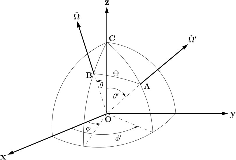
FIGURE 1. Coordinate system for scattering by a volume element at O. The points C, A and B are located on the unit sphere. The incident light beam with Stokes vector
Here
2.2 Polarized Radiation
To generalize Eq. 2 to apply to polarized radiation, the scalar source function must be replaced by the appropriate vector version. Hence, the multiple-scattering term
where I (τ, u′, ϕ′) is the Stokes vector, and P (τ, u′, ϕ′; u, ϕ) is the scattering phase matrix. The first element of the vector Sms(τ, u, ϕ) represents the energy per unit solid angle, per unit frequency interval, and per unit time that is scattered by a unit volume in the direction (u = cos θ, ϕ). Hence, in a plane-parallel (slab) geometry, the integro-differential vector radiative transfer equation (VRTE) for polarized radiation is expressed in terms of a Stokes vector I (τ, u, ϕ) as
where the vector source function is
Here Sms(τ, u, ϕ) is given by Eq. 6 and the source term Q (τ, u, ϕ), due to beam and thermal sources, is given by:
The first term on the right hand side of Eq. 9 describes the incident beam Sb in direction (−μ0, ϕ0), which is attenuated at depth τ by a factor
where the superscript T denotes the transpose, and where the first or second expression corresponds to the choice of Stokes vector representation,
where B is the Planck function, and where the first or second expression corresponds to the choice of Stokes vector representation. We have set μ0 ≡|u0|≡| cos θ0|, where θ0 is the polar angle of the incident light beam.
2.3 Effects of Earth Curvature–The Pseudo-Spherical Approximation
For many applications plane-parallel geometry is adequate. For large solar zenith angles (θ0 ≥ 70° and for near horizontal polar viewing angles θ), however, the plane-parallel approximation (PPA) provides inaccurate results. Then the Earth curvature must be considered. Large solar zenith angles occur around the times of sunrise and sunset at any location on a planet. Such large solar zenith angles are present, for example, in observations made by instruments onboard geostationary satellites that observe a large part of Earth’s disk throughout the day. Sensors deployed on polar-orbiting satellite platforms also observe at large solar zenith angles at high latitudes.
As discussed by several investigators (see He et al. (2018) and references therein), the so-called pseudo-spherical approximation (PSA) (Dahlback and Stamnes, 1991) represents a very useful correction to the plane-parallel approximation. In the PSA the direct beam single-scattering term, also called the solar pseudo-source term, is treated in spherical geometry while the multiple-scattering term is treated using the PPA. Hence, in the PSA the exponential attenuation in Eqs. 4 and 9 is replaced by the Chapman function, that is, exp (−τ/μ0) → exp (−τCh(μ0)), where the Chapman function Ch(μ0) takes Earth curvature into account, but ignores refraction. As shown by He et al. (2018) the influence of Earth curvature increases rapidly with solar zenith angle, being up to 1, 3, and 12% for solar zenith angles of 75°, 80°, and 85°, respectively.
2.4 Scattering Phase Matrix
The development of vector radiative transfer theory may start with the Stokes vector representation
where the phase difference δ is δ∥ − δ⊥. The connection between the
where
The degree of polarization is defined as
so that 0 ≤ p ≤ 1, where p = 1 corresponds to completely polarized light and p = 0 to natural (unpolarized) light. The degree of circular polarization is defined as
the degree of linear polarization as
and alternatively, when U = 0 as
The transverse electric field vector
where A is a 2 × 2 matrix, referred to as the amplitude scattering matrix. The corresponding linear transformation connecting the Stokes vectors of the incident and scattered fields in the scattering plane is called the Mueller matrix (in the case of a single scattering event). For scattering by a small volume containing an ensemble of particles, the ensemble-averaged Mueller matrix is referred to as the Stokes scattering matrix F. Finally, when transforming from the scattering plane to a fixed laboratory frame, the corresponding matrix is referred to as the scattering phase matrix P.
2.4.1 Stokes Vector Representation IS = [I,Q,U,V]T
The scattering geometry is illustrated in Figure 1. The plane AOB, defined as the scattering plane, is spanned by the directions of propagation of the incident parallel beam with Stokes vector
If in a small volume of particles any of the following conditions are met (Hovenier and van der Mee, 1983) 1) each particle in the volume element has a plane of symmetry, and the particles are randomly oriented, 2) each volume element contains an equal number of particles and their mirror particles in random orientation, 3) the particles are much smaller than the wavelength of the incident light, then the Stokes scattering matrix in the IS = [I,Q,U,V]T representation has the following form
Each of the six independent matrix elements in Eq. 20 depends on the scattering angle Θ, and will in general also depend on the position in the medium. For spherical particles, the matrix in Eq. 20 simplifies, since a1 = a2 and a3 = a4, so that only four independent elements remain.
Two rotations are required to connect the Stokes vector of the scattered radiation to that of the incident radiation. As illustrated in Figure 1, the first rotation is from the meridian plane OAC, associated with the Stokes vector
Here i1 and i2 are the angles between the meridian planes of the incident and the scattered radiation, respectively, and the scattering plane (Figure 1).The Stokes rotation matrix RS represents a rotation in the clockwise direction with respect to an observer looking into the direction of propagation (Chandrasekhar, 1960). For rotation by an arbitrary angle of ω (0 ≤ ω ≤ 2π) it can be written as
Hence, according to Eq. 21, the scattering phase matrix, which connects the Stokes vector of the scattered radiation to that of the incident radiation, is obtained from the Stokes scattering matrix FS(Θ) in Eq. 20 by
where RS (π − i2) = RS (−i2) since the rotation matrix is periodic with a period π.
According to Eq. 21 (see also Figure 1), the Stokes vector
Carrying out the matrix multiplications in Eq. 23 one finds:
where aj = aj(Θ), j = 1, … , 4, bj = bj(Θ), j = 1, 2, and
A comparison of Eqs. 20 and 24 shows that only the corner elements of FS(Θ) remain unchanged by the rotations of the reference planes. The (1.1)-element of both the scattering phase matrix PS(Θ) and the Stokes scattering matrix FS(Θ) is the scattering phase function. Also, since the (4.4)-element of the scattering phase matrix remains unchanged by the rotations, the state of circular polarization of the incident light does not affect the intensity of the scattered radiation after one scattering event.
To compute PS(θ′, ϕ′; θ, ϕ) given by Eq. 23 we must relate the angles θ′, ϕ′, θ, and ϕ on the left side with the angles i1, i2, and Θ on the right side. Using spherical geometry, we may apply the cosine rule for Θ, θ, and θ′ successively, in Figure 1, to obtain (u = cos θ, u′ = cos θ′) (Hovenier et al., 2004)
The trigonometric functions for the double angles can be obtained by using
and
or
where i is i1 or i2.
Equations 25–32 describe the conventional way to determine the variables C1, S1, C2, and S2.
A better approach to compute the variables C1, S1, C2, and S2 appearing in PS(θ′, ϕ′; θ, ϕ) given by Eq. 24 is described in a recent publication (Berk, 2022). This new approach can be described as follows. Defining
we have
and it can be shown that the variables C1, S1, C2, and S2 are given by
The advantage of using Eqs. 33–38 instead of Eqs. 25–32 is that they eliminate numerical instability issues and the need to treat positive and negative relative azimuth angles as separate cases (Berk, 2022).
We now have all the information needed to compute the scattering phase matrix [see Eq. 24] as a function of the three variables u = cos θ, u′ = cos θ′, and Δϕ = ϕ′ − ϕ. If there is no difference in azimuth (i.e. ϕ′ − ϕ = 0), then the meridian planes of the incident and scattered beams in Fig. 1 coincide with the scattering plane. Hence, there is no need to rotate the reference planes (R( − i2) and R( − i1) both reduce to the identity matrix), so that
It follows from the cosine law of spherical geometry
that the phase matrix is invariant to three basic changes in the polar angles u′ and u and azimuthal angles ϕ′ and ϕ which leave the scattering angle unaltered: 1) changing the signs of u and u′ simultaneously: PS(−u′, − u, ϕ′ − ϕ) = PS(u′, u, ϕ′ − ϕ), 2) interchange of u and u′: PS(u′, u, ϕ′ − ϕ) = PS(u, u′, ϕ′ − ϕ) 3) interchange of ϕ and ϕ′: PS(u′, u, ϕ′ − ϕ) = PS(u′, u, ϕ − ϕ′). Also, if the b2-element in Eq. 24 is zero, then the Stokes parameter V is scattered independently of the others, according to the phase function a4(Θ), and the remaining part of the scattering phase matrix referring to I, Q, and U becomes a 3 × 3 matrix:
Finally, in a plane-parallel or slab geometry, there is no azimuth-dependence for light beams traveling in directions perpendicular to the slab (either up or down). Thus, if either the incident or the scattered beam travels in a perpendicular direction, we may use the meridian plane of the other beam as a reference plane for both beams. Since this plane coincides with the scattering plane, Eq. 39 applies in this situation too.
For Rayleigh scattering with parameter
For the first scattering event of the scalar RTE, only the (1.1)-element of Eq. 42 matters, and leads to the scattering phase function given by
2.4.2 Stokes Vector Representation
The Stokes vector
where D is given by Eq. 14, so that I = I‖ + I⊥, and Q = I‖ − I⊥. Denoting the Stokes vector obtained after a rotation by
we find
Hence, the rotation matrix for the Stokes vector in the representation
The scattering phase matrix P(Θ) in the Stokes vector representation
Similarly, the Stokes scattering matrix F(Θ) associated with the Stokes vector representation
In the Stokes vector representation
where
From Eq. 50 we see that for an incident beam of natural unpolarized light given by
Thus, for unpolarized incident light, the scattered light at right angles (Θ = 90°) to the direction of incidence defines the depolarization ratio:
whereas the degree of linear polarization becomes [Eq. 18]:
2.4.3 Generalized Spherical Functions–The Greek Constants
For the scalar RTE, only the a1(Θ) element of the Stokes scattering matrix Eq. 20 is relevant, and this element is the scattering phase function given by Eq. 69 in general, and by Eq. 43 for Rayleigh scattering. The scattering phase function can be expanded in Legendre polynomials [see Eq. 69], which enables expression as a Fourier cosine series.
In a similar manner, the scattering phase matrix can be expanded in generalized spherical functions. In the Stokes vector representation IS = [I,Q,U,V]T, the scattering phase matrix is PS(Θ) = PS(u′, u; ϕ′ − ϕ) with u = cos θ, θ being the polar angle after scattering, and u′ = cos θ′, θ′ being the polar angle prior to scattering. Similarly, ϕ and ϕ′ are the azimuth angles after and prior to scattering, respectively. To expand in generalized spherical functions, the scattering phase matrix is first expanded in a (M + 1)-term Fourier series in the azimuth angle difference (Δϕ′ = ϕ′ − ϕ):
where
We use an addition theorem for the generalized spherical functions to express the Fourier expansion coefficient matrices directly in terms of the expansion coefficients of the Stokes scattering matrix FS(Θ) [see Eq. 20] as follows (Siewert, 1981; Siewert, 1982; Mishchenko, 1991):
where Δ3,4 = diag (1, 1, −1, 1). The matrix Am (u′, u) is given by:
The matrix
where
and the functions
and
Here the Greek constants αj,ℓ and βj,ℓ are expansion coefficients, and aj(Θ) and bj(Θ) are the elements of the Stokes scattering matrix FS(Θ) in Eq. 20. An example of Greek constants for Rayleigh scattering is provided in Table 1 (see Mishchenko and Travis (1997)) where
and ρ is the depolarization ratio given by Eq. 53.
We note that in the scalar (unpolarized) case all components of the Stokes scattering matrix FS(Θ) [see Eq. 20] are zero except for a1(Θ), and:
since
3 Solution of the Vector Radiative Transfer Equation
3.1 Isolation of Azimuth Dependence
We start from the scattering phase matrix expanded in a Fourier series (see Eq. 55) (Δϕ′ = ϕ′ − ϕ):
To isolate the azimuth dependence of the radiation field we expand the Stokes vector I (τ, u, ϕ) in the VRTE [Eq. 7] and the source term Q (τ, u, ϕ) in Eq. 9 in a Fourier series in a manner similar to the expansion of the scattering phase matrix in Eq. 70 (Δϕ0 = ϕ0 − ϕ):
where the subscript s or c denotes sine or cosine mode. Using these expansions, we obtain the following equations for the Fourier components of the VRTE (see Stamnes and Stamnes (2015) for details)
For scattering by randomly oriented particles, the Fourier coefficient matrix
where we have defined
3.1.1 Vector Radiative Transfer Equation for the Combined Mode
We note that the
After substantial manipulations, one can show that the mth term of the homogeneous VRTE of the combined modes can now be written as (m ∈ [0, 1, 2, … , 2N]):
where the combined scattering phase matrices are defined as:
For the special m = 0 case, we have
Equations 79 and 80 are two independent differential equations to be solved.
3.2 The Discrete Ordinate Method
The discrete ordinate method consists of replacing the integration over u′ in Eqs. 79 and 80 by a discrete sum by introducing the Gaussian quadrature points uj (the discrete ordinates) and corresponding weights wj. For each Fourier component one obtains (i = ±1, ±2, … , ±2N):
The convention for the indices of the quadrature points is such that uj < 0 for j < 0, and uj > 0 for j > 0. These points are distributed symmetrically about zero, i.e., u−j = −uj, and the corresponding weights are equal, i.e. w−j = wj.
The solution of the discrete ordinate approximation to the VRTE Eqs. 83 and 84 is analogous to that of the scalar RTE. Detailed derivations, including the removal of the notorious ill-conditioning problem, can be found elsewhere (Schulz et al., 1999; Siewert, 2000; Stamnes and Stamnes, 2015), and will not be repeated here.
3.3 Discrete Ordinate Radiative Transfer Upgrades
Below we describe some new important upgrades of VDISORT:
• First, a new algorithm to handle the complex eigenvalue/eigenvector problem is developed and implemented in VDISORT to give an accurate computation of the V component of the Stokes vector.
• Second, a reduction of the dimension of the complex eigenvalue problem is developed to reduce the computational burden, and the boundary condition for the complex eigenvalue/vector case is discussed.
• Third, to obtain solutions at arbitrary polar angles, we have developed and implemented an accurate ISF approach that works for both real and complex eigensolutions and an arbitrary bidirectional reflectance distribution matrix is added to compute the polarized reflectance at the lower boundary.
• Fourth, a pseudo-spherical treatment has been implemented to provide important corrections for Earth curvature effects at large (near horizontal) solar zenith and observation polar angles.
• Finally, a single-scattering solution is developed and used to enhance the accuracy and speed for strongly forward-peaked scattering, such as by large water droplets or ice particles.
3.3.1 Complex Eigenvalues/Eigenvectors
The appearance of complex eigenvalues/eigenvectors in the vector radiative transfer problem stems from the asymmetric structure of the Stokes scattering matrix [ ± b2(Θ) in Eq. 20], or equivalently, from the Greek constant matrix [ ± β2 in Eq. 61]. In the scalar DISORT model, this 4 × 4 scattering matrix degenerates into the scalar scattering phase function Eq. 69 and the complex eigenvalue problem does not occur.
3.3.2 The Complex Homogeneous Solution
By seeking exponential solutions to the homogeneous VRTE’s, Eqs. 83 and 84, one obtains a standard algebraic eigenvalue problem. Writing the VRTE separately for the upward (u > 0) and downward (u < 0) hemispheres, and defining μ = |u| and α = c, s, the homogeneous version of the Fourier components of the VRTE becomes (i = 1, 2, … , 2N):
Seeking solutions to Eqs. 85 and 86 of the form
In the scalar DISORT case real eigenvalues ± kj and eigenvectors g±j (±μj) are obtained, so that the homogeneous solution can be written as a linear combination of the eigensolutions:
For the 4 × 4 VDISORT problem the g±j (±μi) eigenvector in the scalar case must be replaced by a 4 × 1 eigenvector g±j (±μi) for
where Nr is the number of real solutions, Ni is the number of complex conjugate pair solutions, and N = Nr + 2Ni is the number of streams in each hemisphere.
The homogeneous solution in Eq. 89 contains complex numbers that must be converted into real values before solving for the coefficients. Since linear combinations of
The new eigenvalue/vector pairs are real numbers, and the coefficients C ± 1j, C ± 2j will be determined by the top/lower boundary as well as the layer continuity conditions. The beauty of Eq. 90 is that (after the conversion) it has the same form as that of the scalar homogeneous solution, with all of the differences incorporated in the new (4 × 1) eigenvectors
3.3.3 Reduction of the Dimension of the Algebraic Eigenvalue Problem
A reduction of the dimension of the eigenmatrix by a factor of 2 saves a significant amount of computing time. In the scalar DISORT code, this reduction is based on the symmetry pm (μi, μj) = pm (−μi, − μj) of the phase function as explained in detail elsewhere (Stamnes K. et al., 2017).
However, in the vector case, the phase matrix
where the matrix D = diag (1, 1, −1, −1).
This result just tells us that we need to introduce a new phase matrix
In Eq. 85, we simply just multiply by D ⋅D = I in front of the term
Now we may rewrite the VRTE with the proper symmetry structure, which is suitable for the reduction of dimension.
Equations 94 and 95 are identical with Eqs. 85 and 86 if we make the following connections:
To accomplish the reduction of dimension, we define eigenvectors
as well as two 4N × 4N matrices as we did in the scalar case (Lin et al., 2015):
to obtain
Equation 96 is similar to the one obtained in the scalar case, so we may proceed exactly as in that case (Lin et al., 2015).
3.4 Discrete-Ordinate Approximation of the Vector Source Function
In VDISORT, the source function is a 4 × 1 vector, and the discrete-ordinate approximation of the mth Fourier component of the vector source function may be written as
In Eq. 97, the Stokes vector
where the first two summation terms on the right hand side are the homogeneous solution for real eigenvalues/vectors, the following term is the particular solution, and the last two summation terms are the homogeneous solution for complex conjugate eigenvalues/vectors. The real vectors
Substituting Eq. 99 into the vector source function given by Eq. 97, we may write the vector source function [Eq. 97] in a compact form similar to the general solutions [Eq. 99]:
In Eq. 100 the following expressions.
are simply convenient analytic interpolation formulas of g,
3.5 Integration of the Source Function Method–Solutions at User-Desired Polar Angles
The discrete ordinate solutions for the Stokes vector are computed at the quadrature angles as discussed in the previous section. To obtain values at arbitrary angles as desired by the user, an interpolation algorithm has to be implemented. In previous versions of VDISORT, a standard spline interpolation scheme, shown to work well for Rayleigh scattering (Schulz et al., 1999), was used to obtain output at arbitrary polar angles. However, the spline interpolation generally requires a large number of quadrature angles (number of streams), and it may fail when the particles have sharp forward scattering peaks, such as for large cloud droplets or ice crystals, when the Stokes components may change rapidly with polar angle.
A better approach to interpolation is to use the discrete-ordinate solution to derive explicit expressions for the source function that can be integrated analytically. This ISF method is implemented in DISORT (Stamnes et al., 1988; Lin et al., 2015; Stamnes K. et al., 2017) and also in a previous version of VDISORT (Schulz and Stamnes, 2000), but that solution is not valid for the V component of the Stokes vector because the eigenvalues/vectors were assumed to be real. Therefore, the solution must be extended to apply to the general case for which some of the eigenvalues/eigenvectors may be complex. By doing so, we obtain results at arbitrary polar angles for any given number of streams, and we may save computing time by getting accurate results at arbitrary polar angles for a relatively small number of streams. Below we will use the ISF method to derive a new interpolation algorithm that works well also for the complex eigensolutions.
3.5.1 Single-Layer (Homogeneous) Medium
For a slab of thickness τ*, we may solve Eqs. 83 and 84 to obtain.
Using Eq. 100 in Eqs. 105 and 106, we find that for a slab of thickness τ*, the Stokes vectors become
where
Here we assumed k−j = −kj, k−rj = −krj and k−ij = −kij and thus k−cj = −kcj = −krj − ikij.
In Eqs. 107 and 108, the first term on the RHS is due to beam attenuation of the Stokes vector. The first of the following summation terms stems from the integration of the homogeneous solution with real eigensolutions in the vector source function [Eq. 100], whereas the second summation is a new term needed for the complex eigensolutions in the vector source function [Eq. 100]. Because
3.5.2 Multi-Layer (Inhomogenous) Medium
The single-layer case can be extended into a multi-layer medium, for which we need to evaluate the integral by integrating layer-by-layer as follows.
Using Eq. 100 for
with τn−1 replaced by τ for n = p, and
with τn replaced by τ for n = p, and where
It can be verified that for a single layer τn−1 = τ, τn = τL = τ* in Eq. 114; τn = τ, τn−1 = 0 in Eq. 115, they are reduced to Eqs. 107 and 108, as they should.
3.5.3 Numerical Example
Many practical problems including remote sensing applications require Stokes vector components at sensor observing angles. Even though one could envision generating results at sensor observing angles by interpolating or extrapolating the quadrature values to such angles, accurate interpolation of these values is difficult, particularly for optical depths close to zero (upper boundary) and for extrapolation to angles close to μ = 0 and μ = 1.0. For example, Figure 2 shows an example of inaccurate spline interpolation for a benchmark case (Garcia and Siewert, 1989) that has been reproduced by VDISORT.We note that the spline interpolation produces large oscillations, whereas the ISF method, see Eqs. 105 and 106 yields accurate analytic results that agree with the benchmark values at the quadrature angles.

FIGURE 2. Comparison of output for (i) quadrature angles (μ = cos θ, where θ is the polar angle); (ii) spline interpolation; and (iii) analytic results at arbitrary output angles.
We emphasize that the ISF method allows one to compute analytically the radiation field at arbitrary angles and optical depths from the discrete ordinate solutions, both for the scalar radiative transfer problem (Lin et al., 2015; Stamnes K. et al., 2017) and, as shown here, for the vector problem including the complete Stokes vector IS = [I, Q, U, V]T. This capability is one of the unique advantages of the discrete ordinate method. Also, the ISF solutions satisfy the boundary and continuity conditions not only at the discrete set of quadrature angles, but at arbitrary angles μ. In fact, we have found that the ISF method improves the accuracy of the discrete ordinate solution (Schulz and Stamnes, 2000).
3.6 Polarized Reflectance at the Lower Boundary
In Eq. 99 the homogeneous solution contains unknown constants C±j, C ± 1j, and C ± 2j, which are to be determined by the boundary conditions at the top and bottom of the medium and continuity conditions at layer interfaces.
3.6.1 Top Boundary
In VDISORT, we assume that the light at the top of the atmosphere is a direct beam such that the diffuse light contribution is zero:
for m = 0, … , 2N − 1.
3.6.2 Layer Interfaces
At layer interfaces the Stokes vector must satisfy continuity conditions, because by assumption there is no change in the refractive index between layers. Assuming that τn,bottom is the optical depth at the bottom of the nth layer, and that τn+1,top is the optical depth at the top of the (n + 1)th layer, we have.
where the Stokes vector
3.6.3 Lower Boundary
For the RTE, the lower boundary is determined by the bidirectional reflectance distribution function/matrix (BRDF). We introduce the matrix or polarized BRDF as the 4 × 4 reflection matrix R by writing:
The reflection matrix R (−μ′, μ, ϕ − ϕ′) is then expanded in a Fourier series:
The Fourier mode
where.
where
In VDISORT, the implementation of the polarized BRDF has been tested by assuming a vacuum layer above a rough ocean surface (Tsang et al., 1985) and by matching the values of the Stokes vector just above the surface (in the upward direction) with analytic values of the BRDF computed without the Fourier expansion. Figure 3 shows an example of a comparison between VDISORT upward reflected Stokes parameters and analytic Cox-Munk BRDF results for a 1-D Gaussian surface with a wind speed of 5 m/s. The V component vanishes because the reflection from an unpolarized direct beam does not produce circular polarization. The results show that VDISORT reproduced the analytic results except for backscattering (ϕ = 180°) of the U component where the value of zero is given as numerical noise
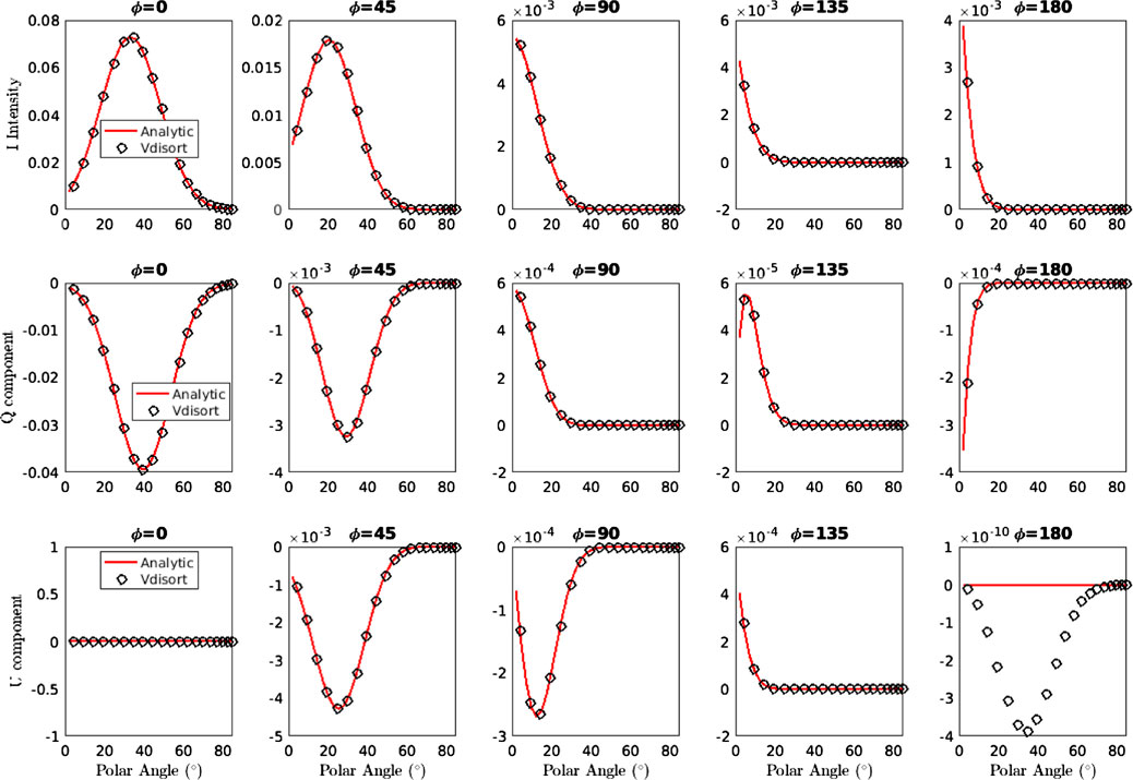
FIGURE 3. Upper panel: The upward reflection of Stokes parameter I (μ, τL, ϕ) just above the lower boundary for a 1-D Gaussian surface with a ‘Cox-Munk’ slope variance distribution for a wind speed of 5 m/s. Middle panel: Same as upper panel except for the Stokes parameter Q (μ, τL, ϕ). Lower panel: Same as upper panel except for the Stokes parameter U (μ, τL, ϕ).
4 The 4 × 4 Solution Versus the 3 × 3 Approximation
In the discrete ordinate method of radiative transfer, we need to determine homogenous and particular solutions to arrive at the general solution. The particular solution is formulated as a set of linear equations Ax = b that can quickly be solved using standard techniques of linear algebra, for example Gaussian elimination. The most time-consuming step is solving the homogenous problem, which is formulated as a standard algebraic eigenvalue problem (A− λ)x = 0. In the case of the 4 × 4 solution, this eigenvalue problem involves matrices of size 4N × 4N, where N is the number of quadrature points or “streams” in the upper and lower hemispheres, since a reduction of dimension step (Section 3.3.3) is used to reduce the matrix dimension from 8N × 8N–4N × 4N. This step is completely analogous to that used in DISORT (Stamnes et al., 1988) to reduce a matrix of dimension 2N × 2N to N × N. Since the presence of the sign on b2 in Eq. 20 leads to a matrix A in the algebraic eigenvalue problem that cannot be made symmetric, the eigenvalues and corresponding eigenvectors in the 4 × 4 representation occur in complex conjugate pairs. In the 3 × 3 approximation, the 4th row and column in Eq. 20 are simply omitted, and the resulting impact on the scattering phase matrix is obtained by setting b2 = 0 in Eq. 24 which results in Eq. 41. Then the matrix A is symmetric implying that the resulting eigenvalues and eigenvectors are real. Note that setting b2 = 0 in the 4 × 4 representation leads to I, Q, and U parameters identical to those obtained in the 3 × 3 approximation.
Since setting b2 = 0 decouples the V component from I, Q, and U, the eigenvalue problem required to solve the homogeneous system in N discrete ordinates is reduced from solving a 4N × 4N system to solving a 3N × 3N system. The computational burden of solving an eigenvalue problem scales like n3 where n is the dimension of the matrix. Therefore, the 3 × 3 approximation reduces the computational burden by a theoretical factor of 43/33 ≈ 2.37. Since the resulting eigenvectors and eigenvalues for the 3N × 3N system are real, significant further computational savings are obtained by using an eigensolver, such as ASYMTX available in the DISORT package (Stamnes et al., 1988) that avoids unnecessary complex arithmetic. In the 4 × 4 case some of the eigenvectors and eigenvalues occur in complex conjugate pairs implying that complex arithmetic must be considered to obtain accurate solutions when b2 ≠ 0.
A comparison of results produced by VDISORT and by a doubling-adding method (VLBLE) is provided in Figure 4 (Stamnes S. et al., 2017), where the reflected components are plotted against the polar angle θR, where θR = 0° is the zenith direction, and θR = 90° is the horizon. The transmitted components are plotted against the polar angle θT, where θT = 0° is the nadir direction, and θT = 90° is the horizon. We note that the results for I and Q produced by the 3 × 3 approximation are essentially identical to the more computationally demanding 4 × 4 results.
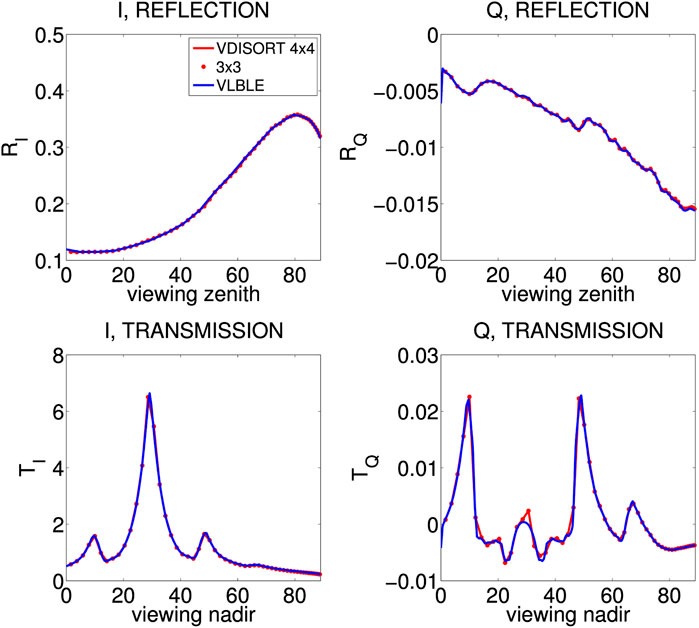
FIGURE 4. Top panels: reflected I and Q components at polar angles θR; bottom panels: transmitted I and Q components at polar angles θT. The incident Stokes vector is IS =[1,0,0,0]. The actual reflection and transmission for I and Q are scaled by a factor
The results shown in Figure 4 pertain to a cirrus cloud consisting of non-spherical ice crystals. The adequacy of the 3 × 3 approximation was investigated for spherical particles by Hansen (1971) who concluded that it is usually adequate to work with 3 × 3 matrices to compute multiple-scattering polarization properties. Hansen (1971) investigated errors only of the reflected radiance and the degree of polarization; errors for the individual Stokes components Q and U, and transmittances were not considered. The results shown in Figure 4 suggest that the 3 × 3 approximation holds not only for water clouds, but also for non-spherical ice crystals, and that it applies not just to the reflected radiation, but also to the transmitted radiation and to the Stokes parameters Q and U (not shown) (Stamnes S. et al., 2017).
5 Single-Scattering Solution
Introducing the half-range Stokes vectors (the ± signs denote the upper (+) and the lower (-) hemispheres, respectively).
and similar definitions for S±(τ, μ, ϕ), Eq. 7 may be re-written as (μ ≡|u|).
5.1 Single-Layer (Homogeneous) Medium
For a homogeneous slab, we adopt the following notation:
1) τ0 is the optical depth at the upper boundary (top of the slab);
2) τb is the optical depth at the lower boundary (bottom of the slab).
Integrating Eq. 131 from τb to τ and Eq. 132 from τ0 to τ (τ0 ≤ τ ≤ τb), and solving for I±(τ, μ, ϕ) we obtain.
Equations 133 and 134 show that if the source functions S±(t, μ, ϕ) are known, we can obtain a solution to the radiative transfer problem by integration (numerically or analytically).
In the single-scattering approximation, we omit the multiple-scattering term in Eq. 8, so that the source function S±(τ, μ, ϕ) in Eq. 9 simply becomes:
The first term on the RHS of Eq. 135 is proportional to the incident beam Sb which for an unpolarized incident beam is given by Eq. 10, while the second term is due to thermal emission, which is unpolarized, and St(τ) and is given by Eq. 11.
5.2 Multi-Layer (Inhomogeneous) Medium
The vertical variation of the inherent optical properties (IOPs) in a slab may be dealt with by dividing it into a number of adjacent, horizontal layers in which the IOPs are taken to be constant within each layer, but allowed to vary from layer to layer. The number of layers should be large enough to resolve the vertical variation in the IOPs. In such a multi-layered medium, consisting of a total of L layers, we may evaluate the integrals in Eqs. 133 and 134 by integrating layer by layer as follows (τp−1 ≤ τ ≤ τp and μ > 0, τb = τL, τ0 = 0) ignoring the boundary terms (setting I+(τb, μ, ϕ) = 0 and I−(τ0, μ, ϕ) = 0):
We can evaluate the integrals in Eqs. 136 and 137 either numerically or analytically if the source function
5.3 Alternative Single Scattering Solution
Another way to understand the one-layer single-scattering solution is to consider the output I±(τ, μ, ϕ) as coming from two sources: 1) the attenuated incident radiation from the layer boundary and in the same direction (μ±, ϕ), and 2) the source term contribution from the direct beam scattering. As seen in Section 5.1 [Eqs. 133 and 134], the attenuated boundary contribution is the first term on the right, while the source term is the second term on the right.
Next, we consider the single-scattering solution at layer boundaries τn with n ∈ [0, 1, 2, ⋯L] for a multi-layer medium. Since there is no diffuse radiation at the following two boundaries: 1) TOA (Top-Of-Atmosphere) downward τ0; 2) BOA (Bottom-Of-Atmosphere) upward τL, we have1:
Once we have specified the boundary conditions, the one-layer solution can be called consecutively to create the layer boundary radiation of the next layer. Hence, for n = 1, 2, … , L, we may recursively compute the downward radiation as:
Similarly, for n = L, … , 2, 1, we may recursively compute the upward radiation as:
Having obtained all layer boundary contributions in this manner, we may simply apply the single-layer solution again to get the I±(τ, μ, ϕ) at arbitrary optical depth τ.
5.4 Single Scattering Correction
The single-scattering correction is a post-processing step that further improves the accuracy of radiance output by correcting the single-scattering term. It was developed by Nakajima and Tanaka Nakajima and Tanaka (1988) and can be used together with several phase matrix truncation methods (Wiscombe, 1977; Hu et al., 2000; Lin et al., 2018).
In many radiative transfer models, the phase function/matrix is expanded in generalized spherical functions (see Section 2.4.3). However, for strongly forward-peaked scattering a large number of phase element expansion coefficients are needed for accurate representation of the phase function/matrix. Due to the computational burden incurred by use of such a large number expansion coefficients, a truncation method is commonly applied so that only the first 2N elements are used, where 2N is set to be equal to the number of streams. This method greatly improves the computational efficiency, but also introduces radiance errors due to the approximate phase matrix representation. Since the truncation reduces the scattering cross-section and thereby enhances the direct beam contribution, the differential optical depth dτ and the single-scattering albedo ϖ are both being scaled as follows.
where the factor f depends on the particular truncation method used (Wiscombe, 1977; Hu et al., 2000; Lin et al., 2018).
The single-scattering correction method (Nakajima and Tanaka, 1988) was designed to decrease the error incurred by the truncation. To this end we replace the approximate single-scattering solution obtained by use of the truncated phase matrix by the correct single-scattering solution obtained from the accurate phase matrix as described in Section 5.3. Denoting P and P* as the original and truncated phase matrix, and I* as the singly-scattered radiance, we may write the single-scattering correction algorithm as follows (Nakajima and Tanaka, 1988):
On the right hand side of Eq. 144, the first term
6 Discrete Ordinate Radiative Transfer Test Results
Schulz et al. (1999) tested a previous of VDISORT against benchmark results provided by Garcia and Siewert (1989). The result of the first three Stokes components were reproduced, but the V component was not considered. In our new version, this issue is fixed by implementing the complex eigensolutions as already discussed. The current version of VDISORT has been tested against benchmark results provided by (Garcia and Siewert, 1989) and Siewert (2000), and excellent agreement was found (Lin, 2016). Here we provide comparisons with benchmark results provided Kokhanovsky et al. (2010) for more challenging phase matrices that require more than 100 terms in the phase matrix expansion.
6.1 Comparison With Benchmark Results
The Kokhanovsky et al. (2010) benchmark results were provided for the Stokes parameters of both reflected and transmitted light in the case of molecular, aerosol, and cloudy multiple-scattering media at the wavelength λ = 412 nm. A black underlying surface for three values of the relative azimuth angles ϕ − ϕ0 = 0, 90, 180° were considered and the solar zenith angle was set to 60°. The optical thickness was set to 0.3262 for all three single layer cases. Since the Rayleigh test is simple and has been well tested in previous versions of VDISORT, we will focus on the more challenging aerosol and cloud cases.
The phase matrix elements for all three cases are shown in Figure 5. Because aerosol and cloud particles are much larger than molecules, their phase matrices were calculated using Mie theory (Kokhanovsky et al., 2010). In contrast to Rayleigh scattering, aerosol and cloud particles both have a strong forward-scattering peak. There are also two peaks around 137° in scattering angle that correspond to the primary and secondary rainbows.
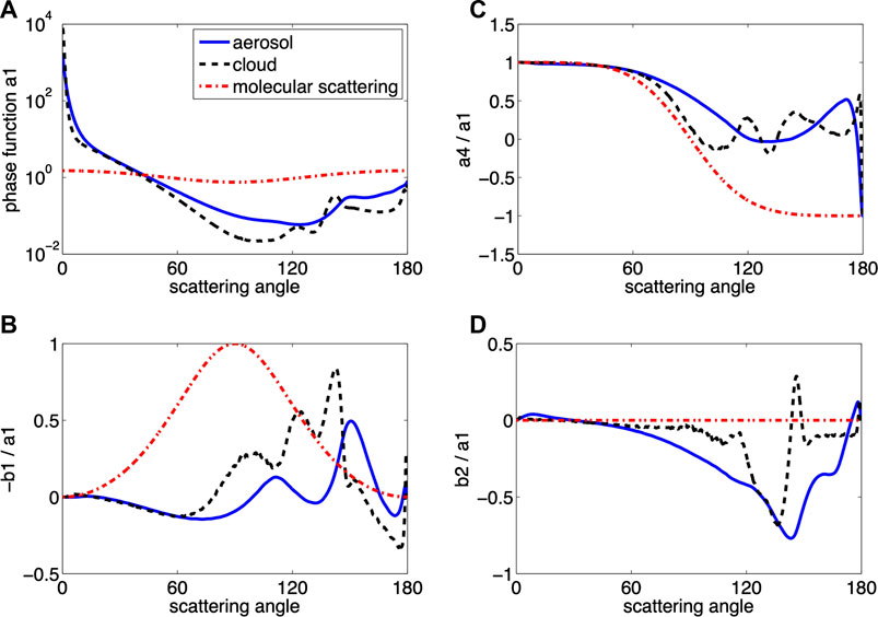
FIGURE 5. (A) Normalized phase function a1; (B) − b1/a1; (C) a4/a1; (D) b2/a1 (Kokhanovsky et al., 2010).
The sharp forward-peaked scattering of aerosol and cloud particles shown in Figure 5 implies that a large number of terms in the Fourier expansion is required for accurate representation of the phase matrix. In fact, Kokhanovsky et al. (2010) provide about 1,000 terms of Greek constants, and below we use the first 148 terms for both the aerosol and cloud cases in VDISORT in an attempt to match the benchmark results.
6.1.1 Aerosol Case
The normalized log-normal density distribution of aerosol particles considered in the benchmark computations of Kokhanovsky et al. (2010) had mode radius rg = 0.3 μm corresponding to a mode size parameter of
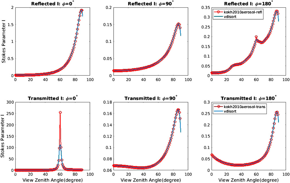
FIGURE 6. The Stokes parameter I (τ, μ, ϕ) for the aerosol scattering case for reflected (top) and transmitted (bottom) light. Number of discrete ordinate streams, NSTR = 148.
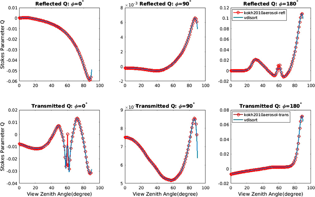
FIGURE 7. The Stokes parameter Q (τ, μ, ϕ) for the aerosol scattering case for reflected (top) and transmitted (bottom) light. NSTR = 148.
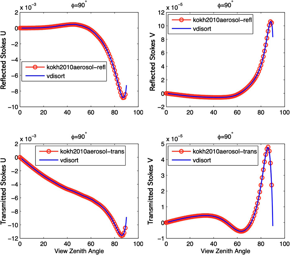
FIGURE 8. The Stokes parameter U (τ, μ, ϕ) (left) and V (τ, μ, ϕ) (right) for the aerosol scattering case for reflected (top) and transmitted (bottom) light. The U and V components vanish for ϕ =0° and ϕ =180°. NSTR = 148.
6.1.2 Cloud Case
Benchmark results for a homogeneous slab of optical thickness 5 consisting of a log-normal distribution of cloud particles with rg = 5 μm (mode size parameter of

FIGURE 9. Upper panel: The Stokes parameter I (τ, μ, ϕ) for the cloud scattering case for reflected (top) and transmitted (bottom) light. NSTR = 148. Lower panel: Same as the upper panel except for the Stokes parameter Q (τ, μ, ϕ).
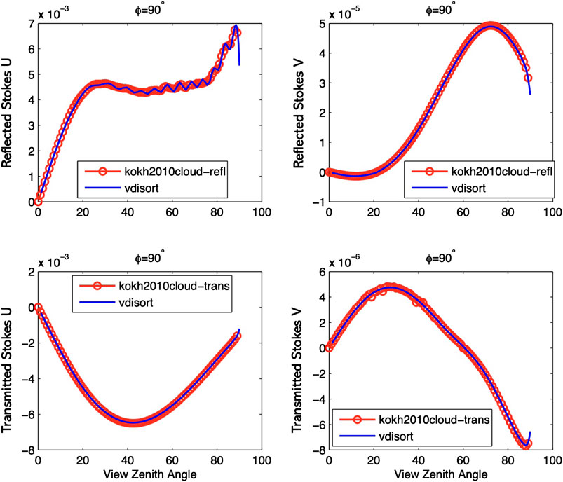
FIGURE 10. The Stokes parameter U (τ, μ, ϕ) (left) and V (τ, μ, ϕ) (right) for the cloud scattering case for reflected (top) and transmitted (bottom) light. The U and V components vanish for ϕ =0° and ϕ =180°. NSTR = 148.
6.2 The Bidirectional Polarized Reflectance Distribution Function (BPrDF)
The BPrDF is the vector equivalent that corresponds to the Bidirectional Reflectance Distribution Function (BRDF) in scalar radiative problems for which only the first component of the Stokes vector, the radiance I, is considered. In this version of VDISORT, BPrDFs for two surface types were implemented: a Lambertian surface and a rough surface with a Gaussian distribution of surface slopes, which is frequently used to model scattering from wind-roughened water surfaces.
In general, both the diffuse light and the direct beam are reflected by BPrDF shown as below:
where μ and μ′ are cosines of the polar angles θ and θ′ and ϕ′ and ϕ are the corresponding azimuth angles. The downward Stokes vector at the surface is denoted Iinc (τ*, μ′, ϕ′), and
A Lambertian surface is a special surface that, regardless of the state of polarization of the incident radiation, gives rise to reflected radiation that is uniform, i.e. isotropic over the upward hemisphere, and unpolarized. Therefore, only the first (m = 0) term in the Fourier expansion contributes. The reflection matrix is given by
where ρL is the surface albedo.
For a wind-roughened water surface, an explicit expression for the reflectance matrix
In Eq. 147, the matrix
σ2 is the mean square surface slope determined by the water surface wind speed w in m s−1. S (μ, μ′, σ) is the shadow term that is only important for the conditions of large wind speeds and large viewing zenith angles (Tsang et al., 1985). To demonstrate how the surface reflectance is applied, a simple example of an atmospheric simulation is considered with a layer of non-absorbing molecules of scattering optical thickness 0.32 and a depolarization factor of 0.04 at 412 nm (Bodhaine et al., 1999) overlying wind-roughened water surfaces with different wind speeds (2, 5, 10 m s−1). The solar zenith angle is set to 30°. Figure 11 shows the upward I, Q, and U components at the top of atmosphere. A glint pattern is clearly evident in the principal plane (Δϕ = (ϕ′ − ϕ) = 0°) for all wind speeds.
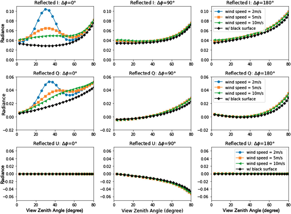
FIGURE 11. TOA polarization components of sunlight reflected from a molecular atmosphere overlying a wind-roughened water surface for three different wind speeds.
6.3 The Single-Scattering Correction
To demonstrate the efficiency and accuracy gained by use of the single-scattering correction (SSC), we provide some examples in this Section. For strongly forward-peaked scattering occurring for particles that are large compared to the light wavelength, use of the delta-M scaling transformation is very useful. Also, use of the ISF method discussed in Section 3.5 helps producing accurate results at polar angles other than the quadrature angles. Figure 12 shows that accurate results for the total polarized radiance (the I Stokes parameter) can be obtained with as little as 16 streams when the SSC is applied in addition to the delta-M and ISF methods. Similar results for the Q and U Stokes parameters are shown in Figures 13, 14.
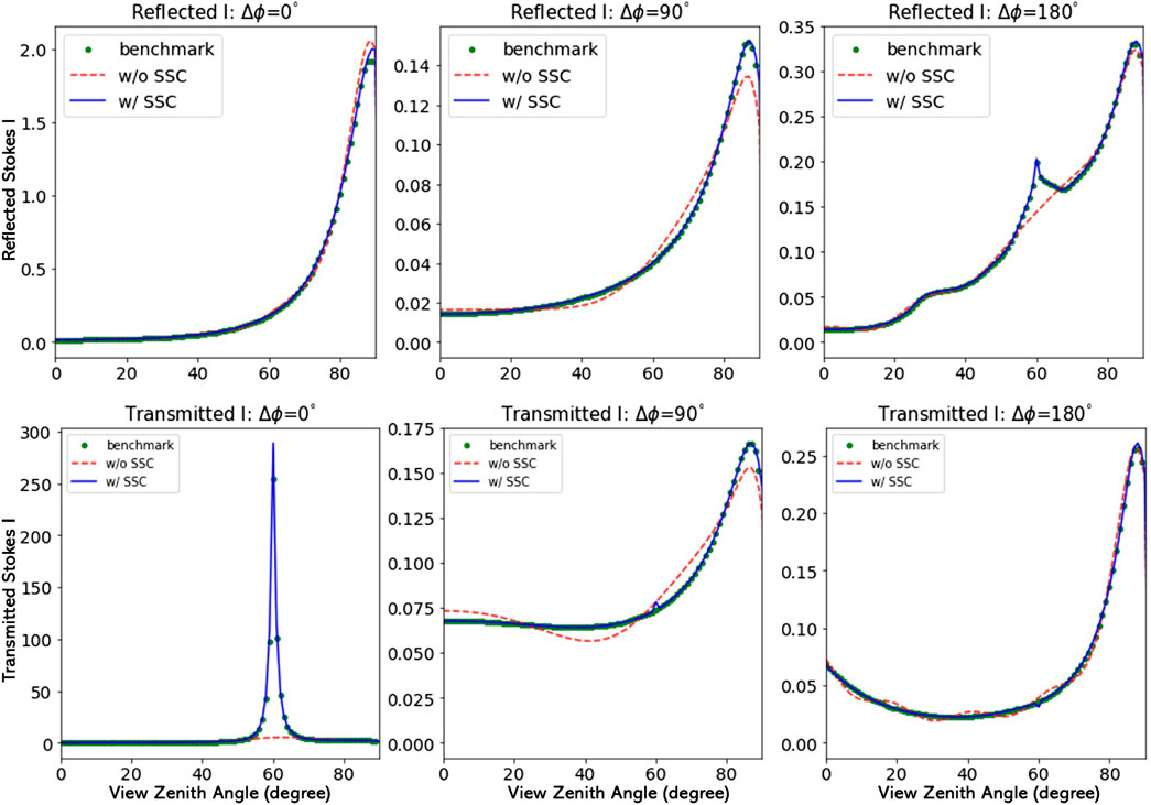
FIGURE 12. The Stokes parameter I (τ, μ, ϕ) for the aerosol scattering case. Top row: Reflected light. Same as top row of Figure 6, but using NSTR = 16 (NSTR = 148 in Figure 6) and with and without SSC. Bottom row: Transmitted light; same as bottom row of Figure 6, but using NSTR = 16 (NSTR = 148 in Figure 6) and with and without SSC.
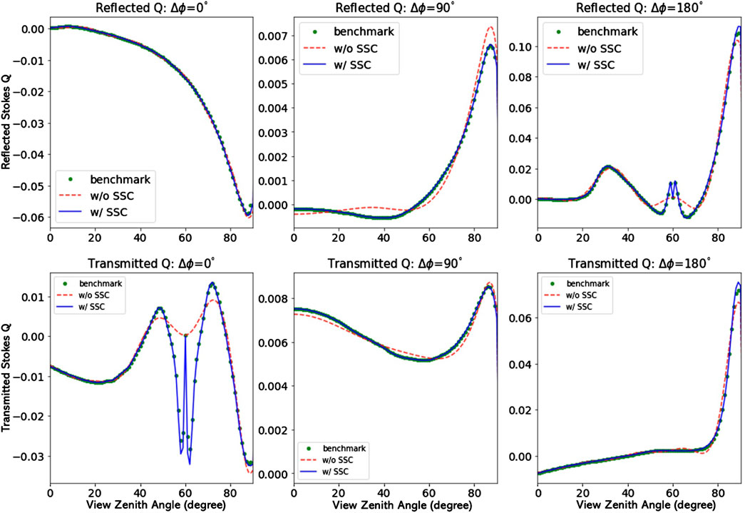
FIGURE 13. The Stokes parameter Q (τ, μ, ϕ) for the aerosol scattering case. Top row: Reflected light. Same as top row of Figure 7, but using NSTR = 16 (NSTR = 148 in Figure 7) and with and without SSC. Bottom row: Transmitted light; same as bottom row of Figure 7, but using NSTR = 16 (NSTR = 148 in Figure 7) and with and without SSC.
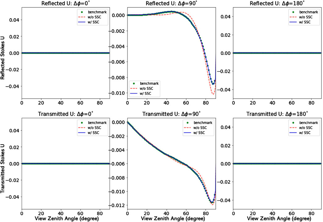
FIGURE 14. The Stokes parameter U (τ, μ, ϕ) for the aerosol scattering case. Top row: Reflected light. Same as top row of Figure 8, but using NSTR = 16 (NSTR = 148 in Figure 8) and with and without SSC. Bottom row: Transmitted light; same as bottom row of Figure 8, but using NSTR = 16 (NSTR = 148 in Figure 8) and with and without SSC.
6.4 Polarized Beam Incidence
So far we have assumed that the incident beam consisted of natural (unpolarized) light (like sunlight). For some applications, like laser (lidar) or lunar beam illumination, the source would be a polarized beam. VDISORT is capable of handling also the general case of an arbitrarily polarized incident beam source. To test the performance of VDISORT for polarized beam incidence, a polarized beam source term Iinc = [I,Q,U,V]T = π[1.0,−0.4.0.2.0.05]T (corresponding to
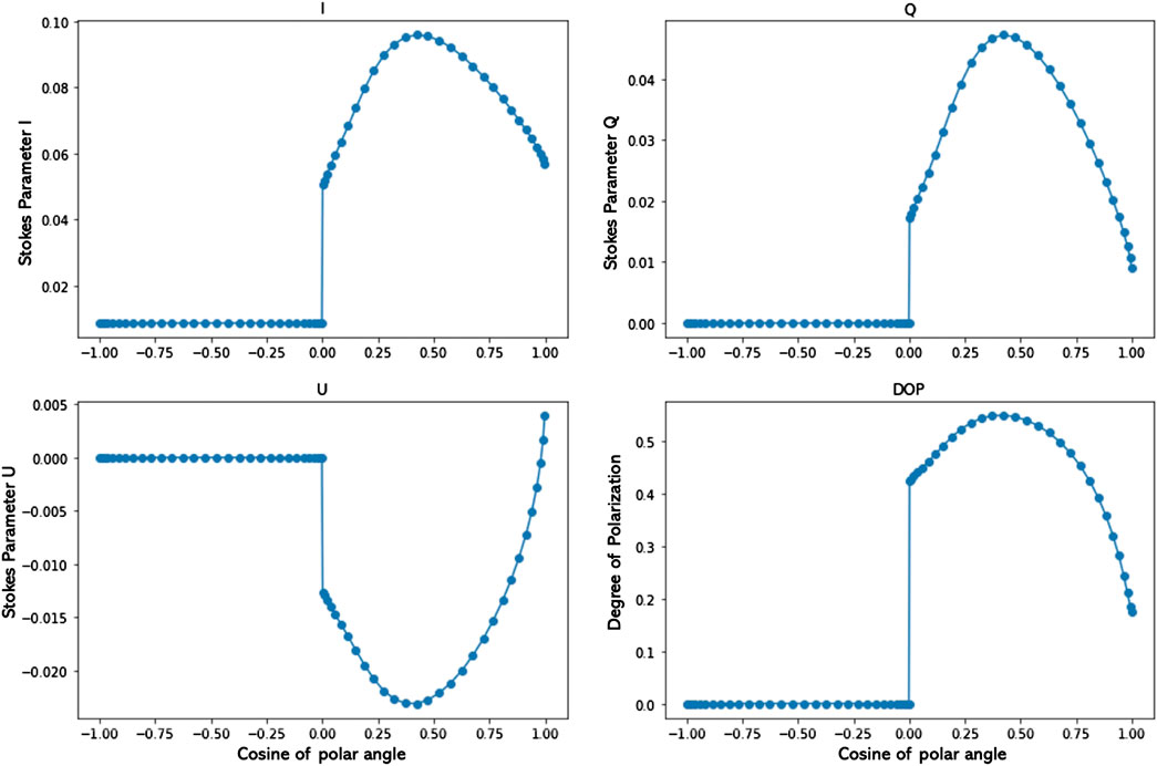
FIGURE 15. The Stokes parameters for polarized beam incidence with
7 Concluding Remarks
A review is provided of the vector discrete ordinate (VDISORT) method of solution to the radiative transfer equation pertinent for polarized transfer of radiation in a vertically stratified medium. Several new features are described and discussed including how to 1) deal with the complex solutions required to compute the V component of the Stokes vector I = [I Q U V]T, 2) obtain accurate radiances at any desired polar observation angles by use of the ISF method, 3) deal with polarized beam incidence at the top of the atmosphere as well as polarized reflectance by the lower boundary, 4) use a pseudo-spherical treatment to correct for Earth curvature effects, and 5) use the single-scattering correction to enhance the efficiency of the method without sacrificing accuracy. Comparisons with benchmark results are provided to demonstrate the versatility of the VDISORT computer code to provide reliable solutions for aerosol and cloud cases including non-spherical ice cloud phase matrices. In particular, it has been shown that as few as 2N = 16 discrete-ordinate streams are sufficient to compute accurate polarized radiances for phase matrices appropriate for ensembles of aerosol particles. We encourage future users to help us improve this freely available tool by 1) reporting on bugs found and how they were fixed, 2) making suggestions for how this tool can be improved, and 3) help make it known to friends and co-workers in need of such a resource that this tool is available.
Data Availability Statement
The raw data supporting the conclusions of this article will be made available by the authors, without undue reservation.
Author Contributions
KS wrote the first draft of the paper based on notes and material provided by ZL. AB helped with the formulation of the equations in Section 2.4.1. All authors provided feedback on the draft including corrections and constructive suggestions. The numerical coding was done primarily by ZL with significant input from SS. Inspection/testing of the numerical VDISORT code was done by WL and IL, who provided substantial suggestions for improvement.
Funding
Partial support for the work described in this paper was provided by grants to Stevens Institute of Technology from the Air Force Research Laboratory as well as NASA’s Remote Sensing Theory Program.
Conflict of Interest
AB is employed by Spectral Sciences.
The remaining authors declare that the research was conducted in the absence of any commercial or financial relationships that could be construed as a potential conflict of interest.
Publisher’s Note
All claims expressed in this article are solely those of the authors and do not necessarily represent those of their affiliated organizations, or those of the publisher, the editors and the reviewers. Any product that may be evaluated in this article, or claim that may be made by its manufacturer, is not guaranteed or endorsed by the publisher.
Supplementary Material
The Supplementary Material for this article can be found online at: https://www.frontiersin.org/articles/10.3389/frsen.2022.880768/full#supplementary-material
Footnotes
1We are ignoring the contribution
References
Berk, A. (2022). A Note on Computing Stokes Phase Matrices for Macroscopically Isotropic Mirror Symmetric Scattering Medium Stokes Scattering Matrices. J. Quantitative Spectrosc. Radiat. Transf. 286, 108220. doi:10.1016/j.jqsrt.2022.108220
Bodhaine, B. A., Wood, N. B., Dutton, E. G., and Slusser, J. R. (1999). On Rayleigh Optical Depth Calculations. J. Atmos. Ocean. Technol. 16, 1854–1861. doi:10.1175/1520-0426(1999)016<1854:orodc>2.0.co;2
Cohen, D., Stamnes, S., Tanikawa, T., Sommersten, E. R., Stamnes, J. J., Lotsberg, J. K., et al. (2013). Comparison of Discrete Ordinate and Monte Carlo Simulations of Polarized Radiative Transfer in Two Coupled Slabs with Different Refractive Indices. Opt. Expr. 21, 9592–9614. doi:10.1364/oe.21.009592
Cox, C., and Munk, W. (1954). Measurement of the Roughness of the Sea Surface from Photographs of the Sun’s Glitter. Josa 44, 838–850. doi:10.1364/josa.44.000838
Dahlback, A., and Stamnes, K. (1991). A New Spherical Model for Computing the Radiation Field Available for Photolysis and Heating at Twilight. Planet. Space Sci. 39, 671–683. doi:10.1016/0032-0633(91)90061-e
De Haan, J., Bosma, P., and Hovenier, J. (1987). The Adding Method for Multiple Scattering Calculations of Polarized Light. Astronomy Astrophysics 183, 371–391.
Garcia, R., and Siewert, C. (1989). The Fn Method for Radiative Transfer Models that Include Polarization Effects. J. Quantitative Spectrosc. Radiat. Transf. 41, 117–145. doi:10.1016/0022-4073(89)90133-7
Hansen, J. E. (1971). Multiple Scattering of Polarized Light in Planetary Atmospheres Part Ii. Sunlight Reflected by Terrestrial Water Clouds. J. Atmos. Sci. 28, 1400–1426. doi:10.1175/1520-0469(1971)028<1400:msopli>2.0.co;2
He, X., Stamnes, K., Bai, Y., Li, W., and Wang, D. (2018). Effects of Earth Curvature on Atmospheric Correction for Ocean Color Remote Sensing. Remote Sens. Environ. 209, 118–133. doi:10.1016/j.rse.2018.02.042
Hovenier, J. W., der Mee, C. D. V., and Domke, H. (2004). Transfer of Polarized Light in Planetary Atmospheres. Dordrecht, Netherlands: Kluwer Academic Publsihers.
Hovenier, J. W., and van der Mee, C. V. M. (1983). Fundamental Relationships Relevant to the Transfer of Polarized Light in a Scattering Atmosphere. Astron. Astrophys. 128, 1–16.
Hu, Y.-X., Wielicki, B., Lin, B., Gibson, G., Tsay, S.-C., Stamnes, K., et al. (2000). δ-Fit: A Fast and Accurate Treatment of Particle Scattering Phase Functions with Weighted Singular-Value Decomposition Least-Squares Fitting. J. Quantitative Spectrosc. Radiat. Transf. 65, 681–690. doi:10.1016/s0022-4073(99)00147-8
Kokhanovsky, A. A., Budak, V. P., Cornet, C., Duan, M., Emde, C., Katsev, I. L., et al. (2010). Benchmark Results in Vector Atmospheric Radiative Transfer. J. Quantitative Spectrosc. Radiat. Transf. 111, 1931–1946. doi:10.1016/j.jqsrt.2010.03.005
Laszlo, I., Stamnes, K., Wiscombe, W. J., and Tsay, S.-C. (2016). “The Discrete Ordinate Algorithm, Disort for Radiative Transfer,” in Light Scattering Reviews (Berlin Heidelberg: Springer), Vol. 11, 3–65. doi:10.1007/978-3-662-49538-4_1
Lin, Z., Chen, N., Fan, Y., Li, W., Stamnes, K., and Stamnes, S. (2018). New Treatment of Strongly Anisotropic Scattering Phase Functions: the Delta-M+ Method. J. Atmos. Sci. 75, 327–336. doi:10.1175/jas-d-17-0233.1
Lin, Z. (2016). Development and Applications of Radiative Transfer Models for Unpolarized and Polarized Light (Hoboken, NJ: Stevens Institute of Technology). PhD Thesis.
Lin, Z., Stamnes, S., Jin, Z., Laszlo, I., Tsay, S.-C., Wiscombe, W., et al. (2015). Improved Discrete Ordinate Solutions in the Presence of an Anisotropically Reflecting Lower Boundary: Upgrades of the Disort Computational Tool. J. Quantitative Spectrosc. Radiat. Transf. 157, 119–134. doi:10.1016/j.jqsrt.2015.02.014
Mishchenko, M. I. (1991). Light Scattering by Randomly Oriented Rotationally Symmetric Particles. J. Opt. Soc. Am. A 8, 871–882. doi:10.1364/josaa.8.000871
Mishchenko, M. I., and Travis, L. D. (1997). Satellite Retrieval of Aerosol Properties over the Ocean Using Polarization as Well as Intensity of Reflected Sunlight. J. Geophys. Res. 102, 16989–17013. doi:10.1029/96jd02425
Nakajima, T., and Tanaka, M. (1988). Algorithms for Radiative Intensity Calculations in Moderately Thick Atmospheres Using a Truncation Approximation. J. Quantitative Spectrosc. Radiat. Transf. 40, 51–69. doi:10.1016/0022-4073(88)90031-3
Schulz, F., and Stamnes, K. (2000). Angular Distribution of the Stokes Vector in a Plane-Parallel, Vertically Inhomogeneous Medium in the Vector Discrete Ordinate Radiative Transfer (Vdisort) Model. J. Quantitative Spectrosc. Radiat. Transf. 65, 609–620. doi:10.1016/s0022-4073(99)00115-6
Schulz, F., Stamnes, K., and Weng, F. (1999). Vdisort: an Improved and Generalized Discrete Ordinate Method for Polarized (Vector) Radiative Transfer. J. quantitative Spectrosc. Radiat. Transf. 61, 105–122. doi:10.1016/s0022-4073(97)00215-x
Siewert, C. (2000). A Discrete-Ordinates Solution for Radiative-Transfer Models that Include Polarization Effects. J. Quantitative Spectrosc. Radiat. Transf. 64, 227–254. doi:10.1016/s0022-4073(99)00006-0
Siewert, C. E. (1981). On the Equation of Transfer Relevant to the Scattering of Polarized Light. Astrophys. J. 245, 1080–1086. doi:10.1086/158884
Siewert, C. E. (1982). On the Phase Matrix Basic to the Scattering of Polarized Light. Astron. Astrophys. 109, 195–200.
Sommersten, E. R., Lotsberg, J. K., Stamnes, K., and Stamnes, J. J. (2010). Discrete Ordinate and Monte Carlo Simulations for Polarized Radiative Transfer in a Coupled System Consisting of Two Media with Different Refractive Indices. J. Quant. Spectrosc. Radiat. Transf. 111, 616–633. doi:10.1016/j.jqsrt.2009.10.021
Stamnes, K., and Conklin, P. (1984). A New Multi-Layer Discrete Ordinate Approach to Radiative Transfer in Vertically Inhomogeneous Atmospheres. J. Quantitative Spectrosc. Radiat. Transf. 31, 273–282. doi:10.1016/0022-4073(84)90031-1
Stamnes, K. (1982). On the Computation of Angular Distributions of Radiation in Planetary Atmospheres. J. Quantitative Spectrosc. Radiat. Transf. 28, 47–51. doi:10.1016/0022-4073(82)90096-6
Stamnes, K., and Stamnes, J. J. (2015). Radiative Transfer in Coupled Environmental Systems. Hoboken, NJ: Wiley VCH.
Stamnes, K., Thomas, G. E., and Stamnes, J. J. (2017a). Radiative Transfer in the Atmosphere and Ocean. 2 edn. New York, NY: Cambridge University Press.
Stamnes, K., Tsay, S.-C., Wiscombe, W., and Jayaweera, K. (1988). Numerically Stable Algorithm for Discrete-Ordinate-Method Radiative Transfer in Multiple Scattering and Emitting Layered Media. Appl. Opt. 27, 2502–2509. doi:10.1364/ao.27.002502
Stamnes, S., Ou, S., Lin, Z., Takano, Y., Tsay, S., Liou, K., et al. (2017b). Polarized Radiative Transfer of a Cirrus Cloud Consisting of Randomly Oriented Hexagonal Ice Crystals: The 3× 3 Approximation for Non-spherical Particles. J. Quantitative Spectrosc. Radiat. Transf. 193, 57–68. doi:10.1016/j.jqsrt.2016.07.001
Tsang, L., Kong, J. A., and Shin, R. T. (1985). Theory of Microwave Remote Sensing. Hoboken, NJ: A Wiley-Interscience Publication.
Weng, F. (1992). A Multi-Layer Discrete-Ordinate Method for Vector Radiative Transfer in a Vertically-Inhomogeneous, Emitting and Scattering Atmosphere – I. Theory. J. Quantitative Spectrosc. Radiat. Transf. 47, 19–33. doi:10.1016/0022-4073(92)90076-g
Keywords: radiative transfer, multiple scattering, polarization, passive remote sensing, ellipsometry and polarimetry, lidar, aerosol detection, oceanic optics
Citation: Lin Z, Stamnes S, Li W, Hu Y, Laszlo I, Tsay S-C, Berk A, van den Bosch J and Stamnes K (2022) Polarized Radiative Transfer Simulations: A Tutorial Review and Upgrades of the Vector Discrete Ordinate Radiative Transfer Computational Tool. Front. Remote Sens. 3:880768. doi: 10.3389/frsen.2022.880768
Received: 21 February 2022; Accepted: 07 June 2022;
Published: 22 July 2022.
Edited by:
Oleg Dubovik, UMR8518 Laboratoire d’optique Atmosphèrique (LOA), FranceReviewed by:
Weizhen Hou, Aerospace Information Research Institute (CAS), ChinaChao Liu, Nanjing University of Information Science and Technology, China
Copyright © 2022 Lin, Stamnes, Li, Hu, Laszlo, Tsay, Berk, van den Bosch and Stamnes. This is an open-access article distributed under the terms of the Creative Commons Attribution License (CC BY). The use, distribution or reproduction in other forums is permitted, provided the original author(s) and the copyright owner(s) are credited and that the original publication in this journal is cited, in accordance with accepted academic practice. No use, distribution or reproduction is permitted which does not comply with these terms.
*Correspondence: Knut Stamnes, a3N0YW1uZXNAc3RldmVucy5lZHU=
 Zhenyi Lin1
 Snorre Stamnes
 Wei Li
 Yongxiang Hu
 Istvan Laszlo
 Si-Chee Tsay
 Alexander Berk
 Jeannette van den Bosch
 Knut Stamnes