- Dipartimento di Elettronica, Informazione e Bioingegneria, Politecnico di Milano, Milan, Italy
Edge computing infrastructures are often employed to run applications with low latency requirements. Users can exploits nodes that are close to their physical positions so that the delay of sending computations and data to the Cloud is mitigated. Since users frequently change their locations, and the resources available in the Edge are limited, the management of these infrastructures poses new, difficult challenges. This paper presents PAPS (Partitioning, Allocation, Placement, and Scaling), a framework for the efficient, automated and scalable management of large-scale Edge topologies. PAPS acts as a serveless platform for the Edge. Service providers can upload applications as compositions of lightweight and stateless functions along with latency constraints. At runtime, PAPS manages these applications by executing them in containers, it changes their placement in the Edge topology according to the geographical distribution of the workload, and efficiently allocates resources according to their needs. This paper also presents the architecture of a PAPS prototype built atop Kubernetes and OpenFaaS. The assessment shows both the feasibility of the approach and the ability of efficiently managing hundreds of serverless concurrent functions and of dealing with intense and unpredictable workload variations.
1. Introduction
Cloud computing allows application providers to rent virtual resources and exploit a virtually infinite degree of scalability (Dustdar et al., 2011). While cloud computing radically changed the way applications are designed, deployed and executed, two main challenges remain open. First, clients always have to invoke remote services that could be deployed extremely far from them (potentially, even in another continent). This could be problematic for real-time applications that require low latency such as augmented reality, self-driving vehicles, and Internet of Things (IoT) applications. Second, user data must be sent to centralized servers, mining user privacy.
Edge computing (Shi and Dustdar, 2016; Satyanarayanan, 2017) aims to move the computations from the cloud to executors that are geographically closer to users such as 5G antennas. Locality and decentralization mitigate network latency and help reduce the amount of data that is transported to and processed by centralized servers, thus improving interactivity and user privacy. An edge infrastructure (or topology) is commonly composed of several computing nodes that are geographically distributed on a certain area. Each node can be connected to another node with a direct network connection or through routing. Some of the nodes can also be unreachable by others if no route exists.
Edge infrastructures are meant to host and execute multiple applications at the same time. As an example, in a smart urban district the dedicated edge topology can execute an augmented reality software for interacting with the surroundings, an application that helps traditional and self-driving vehicles to avoid traffic jams, and another one for supervising and controlling the energy consumption of multiple smart buildings.
The management of these geo-distributed infrastructures poses significant challenges (Shi et al., 2016). Besides considering varying workloads and application performance, one must also take into account the geographical location of users. Ideally, to minimize communication latency, one application could be replicated and deployed on the nodes that are closer to clients. However, this could not always be possible since Edge resources are limited and not virtually infinite as in the cloud.
Another key aspect of managing Edge infrastructures is the speed of control. Time consuming decisions, typical of centralized or heavy weighted approaches, could negatively affect the effectiveness of the runtime management. Systems must cope with highly volatile workloads that are likely-to-happen when edge nodes serve the needs of mobile users of densely populated areas. The speed of management does not only depend on decision time but is also affected by actuation time. The recent development in virtualization solutions lead service providers to move from deployments based on virtual machines (VMs) to ones that exploit containers. Containers (Bernstein, 2014) are a lightweight virtualization technology that works at the operating system (OS) level. The application is wrapped in an isolated environment (i.e., a container) and shares with other containers the underlying OS. This way, containers are faster to boot than VMs since they do not manage a full-fledged OS and they are also faster to be scaled and reconfigured (Felter et al., 2015).
Serverless computing (Baldini et al., 2017; Roberts, 2018) is a recent cloud-based execution model that lets service providers organize applications in lightweight and easy to manage stateless functions. A function is an application slice in charge of a single functionality. Serverless computing abstracts away the underlying infrastructure that is only visible to the cloud provider, which is in charge of deploying functions in containers, allocating resources and planning capacity properly.
This paper proposes PAPS (Partitioning, Allocation, Placement, and Scaling) a solution for the automated, efficient and scalable management of large-scale edge infrastructures. PAPS is based on a hierarchical control system and serverless computing. The approach exploits a hierarchy of three control loops that works at different control periods (the higher the control loop is in the hierarchy, the higher the control period). The first exploits heuristics and periodically partitions an edge topology in communities by considering network connections and delays among nodes. The second control loop works at community-level and is in charge of allocating resources (i.e., containers) to applications and placing them on close-to-users nodes. This control loop uses a mixed integer programming formulation to precisely place applications on the best nodes. We exploit an optimization problem since migration of containers in different nodes is a costly operation and errors should be minimized. Finally, at node level, the third control loop is responsible for quickly re-configuring containers to cope with fast-changing workloads. This level exploits lightweight control theoretical planners that are able to reconfigure containers in less than a second while providing formal guarantees on the control.
A simulation-based implementation of PAPS allowed us to assess this control strategy. Obtained results show the feasibility of the approach and its ability to tackle the management of large-scale edge topologies with up to 100 distinct functions and intense and unpredictable fluctuations of the workload.
This paper extends our previous work (Baresi et al., 2019a) by presenting (i) a prototype of PAPS that exploits Kubernetes1, a well-known container orchestrator, and OpenFaaS2, a framework for the implementation of serverless computing systems, and (ii) additional experiments for the three control loops.
The rest of the paper is organized as follows. Section 2 presents the context and introduces PAPS. Sections 3–5 describe the self-management capabilities provided by PAPS at system, community, and node levels. Section 6 describes the prototype and discusses the evaluation, section 7 surveys related approaches, and section 8 concludes the paper.
2. PAPS in a Nutshell
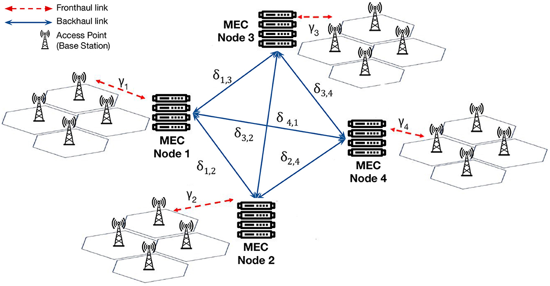
PAPS is designed to manage a large scale edge topology that adheres to the Mobile Edge Computing (MEC) model (Mach and Becvar, 2017; Several authors, 2019), which is illustrated in Figure 1.
An edge topology is composed of a set of geo-distributed MEC nodes, each of them provides a single machine, but multiple MEC nodes can be co-located in a given area. Nodes are connected to one another by using the backhaul network and the network delay between two nodes is defined as δi,j. Mobile clients (users and/or IoT devices) access the system through cellular base stations that are connected to the closest node by the fronthaul network. The communication delay between a base station and its co-located node is defined as γi. A request that is produced by a client connected through a base station to a node i could be served either by i or forward to another node j. Thus, it follows that the total communication delay is defined as:
PAPS considers that each application a ∈ A be composed of one or more function types t ∈ T. Ta is defined as the set of the function types that belongs to application a. At runtime, instances of function types (i.e., functions) f ∈ F are deployed onto nodes using containers (one function per container). Multiple functions can share the same MEC node. A function type could be also instantiated multiple times onto one or multiple nodes to serve highly-intense workloads or ones that are generated in different locations. The response time of a function, that is the round trip time between the arrival of a request and the actual function execution time, is defined as:
where D is the communication delay, Q the time spent by the request in the queue waiting for the execution, and E the execution time. Note that most serverless computing providers try to use existing containers, if possible, and allocate new ones as soon as they are needed. In contrast, if one queued requests for a short period Q, resources (containers) may become available, and thus the number of used resources may decrease. Each function type is associated with a Service Level Agreement (SLA) defined as the maximum allowed response time RTSLA, and a Maximum Execution Time (EMAX) which is the upper limit of a function execution time E (obtained through profiling). Parameters similar to EMAX are commonly exploited in the management of edge infrastructures. PAPS aims to minimize the difference between RTSLA and RT for all the running function instances f ∈ F by employing a hierarchy of three control loops. The lower-level the control loop is, the shorter is its control period. The goal is 2-fold: (i) to maximize the efficient use of resources, and thus the number of functions and users that can be admitted into the system, and (ii) to prevent SLA violations.
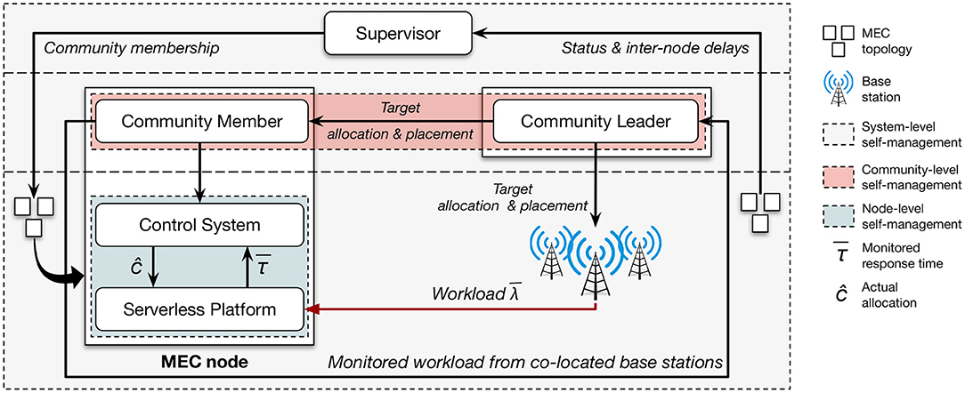
The architecture of PAPS is depicted in Figure 2. For each function type t ∈ T, PAPS requires a descriptor document that defines the memory required by the containers in charge of executing functions of type t and the maximum allowed response time associated with them RTSLA,t. In order to decrease the complexity of the decisions at lower levels, the first control loop (detailed in section 3) exploits a graph based heuristic and aims to partition the edge topology in a set C of communities. In doing so it also defines a community leader that is in charge of managing the community through a community-level control loop. This second control loop is in charge of the allocation of containers and of their placement onto the nodes of the community. More specifically, for a given community c ∈ C and a set of admitted function types Tc, the adaptation problem is 2-fold: one must decide how many containers are needed for each function type, and where (onto which nodes) each container should be placed. Each allocated container works as a execution environment for a specific function f ∈ Fc. The allocation and placement control loop is based on mixed integer programming and will be detailed in section 4. The third control loop (outlined in section 5) works at the node level and is in charge of the dynamic scaling of the resources of running containers (vertical scalability). Scaling actions are based on control-theoretical planners and are meant to continuously refine the initial allocation set by the community-level control loop. Note that, even if the actuation model can vary (Lloyd and et. al., 2018), typically serverless computing providers let users statically define the amount of memory needed to execute a function type and allocate and allocate a fixed amount of CPU shares proportionally (Baldini et al., 2017). This could lead to inefficiency because static allocations cannot cope with highly fluctuating workloads.
3. System-Level Control Loop
Large-scale edge topologies are composed of hundreds or thousands of nodes. If we consider the whole system, its management could be extremely complex and centralized solutions could be ineffective. For this reason, PAPS employs a dedicated control loop that has the only goal of reducing the complexity of the problem that is handled by lower-level control loops.
At the system level, PAPS assumes the existence of a supervisor that has the global view of the edge infrastructure whose goal is to partition the topology in delay-aware network communities. In complex networks, a network is said to have a community structure if its nodes can be (easily) grouped into (potentially overlapping) sets and each set is densely connected internally (Xie et al., 2011). PAPS defines a delay-aware network community as a set of interconnected MEC nodes, whose propagation delay is under a set threshold.
These communities can be generated using different search strategies. In general, the algorithm takes two main parameters: the maximum inter-node delay DMAX, and the maximum size of a community MCS. DMAX is used to generate a sub-graph GDA whose vertices are MEC nodes and edges are network links with a communication delay lower than DMAX. MCS constrains the amount of MEC nodes that could belong to a community. On one hand, this is useful to tame the complexity lower level control loops must handle. On the other hand, a small value of MCS could lead to sub-optimal solutions because communities are managed independently of the others, thus limiting the degree of control.
Produced sub-graph GDA is then used as input for creating the communities. In particular, PAPS exploits the Speaker-listener Label Propagation Algorithm (SLPA) (Xie et al., 2011), whose complexity is O(t * n), where t is the maximum amount of iterations (e.g., t ≤ 30) and n is the total number of nodes. Since the complexity is linear to the number of nodes, this approach can also be used for very large topologies. Xie et al. (2011) suggest that a value of t close to 20 is generally good enough to find good quality communities. As final step, for each community a community leader is randomly selected.
PAPS assumes an almost fixed infrastructure where the network connections remain the same and inter-node delays are expected to be stable. However, PAPS does not execute the partitioning once but it employs two control loops to handle two distinct cases: (i) catastrophic events or unexpected failures that change the initial topology, and (ii) a significant degradation of the performance that implies that community- and node-level control loops are not able alone to handle the incoming traffic. For the first case, PAPS exploits a lightweight heartbeat health check system. Periodically, MEC nodes must send a message to the supervisor to demonstrate their presence. Heartbeat-based protocols are commonly used in distributed systems and do not prejudice the scalability of the solution. This control loop is modeled using a master-slave MAPE loop (Weyns et al., 2013). Monitoring is carried out by all nodes through heartbeat messages that contain the latest measured inter-node delay to all other nodes. The supervisor performs Analysis and Planning by deciding when and how to adapt the community structure in the advent of topological changes. In essence, when the original structure significantly diverges from the actual one (e.g., a certain amount of heartbeat messages are missing), the communities are recreated with the same values for MCS and DMAX. Analysis and Planning also take care of electing new leaders when needed (e.g., a leader's hearbeat is not received timely). Finally, Execution means that each node whose community is modified must update its community membership (i.e., the addresses of leader and other community members). For the second case, PAPS employs a dedicated control loop to help community- and node-level control loops better handle the incoming traffic. As described in section 5, the node-level control loops employ a contention manager to prioritize applications when the resources required to satisfy the SLAs are greater than the actual nodes' capacities. When this scenario occurs each contention manager emits an event that is captured by a dedicated system-level Monitoring component. An Analysis component processes these events and decides when to activate Planning. Since the same events are also captured at the community-level, the Analysis component waits a time threshold TCRITICAL to let community leaders compute new placements and allocations with the goal of better handling the incoming workload. If the system remains unstable, we start a planning phase. Planning recomputes MCS and DMAX by increasing them by a given scaling factor (e.g., 20%), up to a fixed upper bound, to allow the creation of larger and more connected communities. This means that a bigger solution space can be exploited by the community-level control loops, possibly big enough to handle the incoming traffic. It is crucial that both values are increased since larger communities (MCS) must be able to connect more distant nodes (DMAX). A down-scaling action is instead planned when the system is under-saturated to allow a faster and more efficient community-level control loop. After running the partitioning algorithm with the new values, Execution updates the community membership of each node and elects community leaders.
4. Community-Level Control Loop
The control loop at community level aims to minimize SLA violations by properly allocating containers for running applications and to allocate them onto MEC nodes. If violations occur this control loop reacts to bring the community back to its equilibrium.
4.1. Resource Allocation for Overlapping Communities
The communities created by the system-level control loop may be overlapping. This means that some MEC nodes could belong to more than one community at the same time. Thus, the first challenge that arises at the community level is how to distribute the shared resources (i.e., MEC nodes) to the different overlapping communities.
A simple solution is to privilege one community over the others and allocate to it all the shared resources. If we consider a static workload this approach could be efficient, given that the community with a greater incoming working could obtain more resources. However, in a realistic scenario changes to workload happen frequently and without any warnings. Thus, disadvantaged communities might require more resources, while privileged communities could remain underutilized. Instead, resources of shared nodes should be dynamically allocated to the overlapping communities to avoid SLA violations.
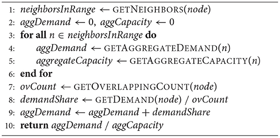
To efficiently allocate resources to overlapping communities, PAPS exploits a strategy that considers two main metrics: the aggregated demand and the aggregated capacity of each community. The former is defined as the amount of containers needed to cope with the total workload. The total workload of a community co is computed as the sum of the incoming requests to the base stations co-located with the MEC nodes that belong to co. The latter is, in turn, the total amount of resources available in a community co computed by considering all the MEC nodes of co but the ones that are shared with other communities. PAPS allocate the shared resources to the overlapping communities proportionally to the ratio of their aggregated demand and capacity.
Algorithm 1 outlines the aforementioned allocation approach. This algorithm is performed greedily for all MEC nodes in the topology that are part of two or more overlapping communities. Given that each community has a numerical identifier, the procedure is executed by the community leader that belongs to the community with the lowest identifier (e.g., if a node n belongs to communities 3, 7, and 8, the leader of community 3 will execute the procedure for node n).
4.2. Container Allocation and Placement
The main objective of the community-level control loop is to allocate containers to applications and to place them in proper MEC nodes within a community. The community leader is in charge of solving the joint allocation and placement problem introduced in section 2. Given that the solution space is greatly reduced by the partitioning step, “centralized” leaders (i) allow the allocation-placement problem to be solved in a single step for the whole community, (ii) do not require complex coordination protocols, and (iii) can safely exploit well-known centralized optimization techniques.
When dealing with the general problem of allocation and placement of resources, one can use either proactive or reactive solutions. Proactive solutions are effective if the workload is characterized by a well-known probabilistic distribution (e.g., a Poisson distribution). In this case, techniques such as queuing theory can be used to predict the number and placement of containers needed to maintain the response time under a certain value. However, at the edge workloads are difficult to predict and the use of a well-known distribution could be unrealistic. Users can freely move among different areas and the level of variability could be greater than what is usually measured in the cloud. For this reason, PAPS employs reactive management for solving the joint allocation and placement problem.
The community-level control loop is activated when workload fluctuations are so intense that the node-level control loops (installed on each node of the community) are unable to keep the system in equilibrium. When this happens, the community-level control loop computes a new allocation and placement for the community. The community-level control loop can be seen as an instance of the regional planner MAPE loop (Weyns et al., 2013). Each community member exploits its geographical position within the MEC topology to monitor and analyze the workload incoming from co-located base stations (see Figure 1). The number of containers required to address a workload while satisfying the SLA is computed at the node level by using a feedback loop with a short control period—compatible with the container start-up time (i.e., up to a few seconds). This number can also exceed the actual resource capacity of the MEC nodes. The community leader gathers and aggregates this information from all the communty nodes and uses them to plan the containers required to satisfy the SLA over a broader control period—compatible with the time needed to compute the optimal placement (i.e., up to a few minutes).
The community-level control loop outputs the fraction of incoming workload for each function type that should be addressed on each node. This means that part of the workload that is generated from a node could be served by a node that belongs to the same community. To do that on each MEC node a load balancer is deployed to route traffic when needed. During the execution phase, load balancers are updated with new routing tables and containers are created/terminated on the community nodes. The node-level control loop is then in charge of properly configure the running containers to optimize their resource usage and prevent undesired SLA violations.
4.3. Problem Formulation
PAPS is independent of the formulation of the optimal allocation and placement problem and different approaches can be used. In this paper we formulate it as a mixed integer programming (MIP) problem as follows:
The decision variable 0 ≤ xt,s,d ≤ 1 denotes the fraction of workload incoming from any base station co-located with a source node , for function type t ∈ T, to be routed to a destination node that belongs to the same community. The objective function (Equation 3a) minimizes the overall network delay that results from placing containers. The first constraint (Equation 3b) states that, for a given function type t ∈ T, the workload incoming at source node must be fully served by a set of destination nodes (note that s could be included in this set).
The second constraint (Equation 3c) defines the boolean variable ct,i that decides if a container for function type t ∈ T should be placed into the MEC node . ct,i is 1 if i is the destination node of some part of the workload incoming into a source node s for function type t ∈ T. Note that for a single function type t ∈ T, PAPS deploys maximum 1 container into each MEC node and allocates an amount of CPU cores that is proportional to the incoming workload. The node-level control loop is in charge of dynamically changing (vertical scaling) the resources allocated to the containers if the workload vary during two community level control loops.
The third constraint (Equation 3d) ensures that the sum of the memory needed by all the containers deployed into a node does not exceed the node memory capacity Mi. Note that the memory needed by a container of type t ∈ T is mt and defined in the function type descriptor. The last constraint (Equation 3e) limits the communication delay for any function type t ∈ T, source node , and destination node . If the decision variable xt,s,d is 0 than no constraint is defined, otherwise the communication delay δs,d should be less than Dt defined as follows:
where 0 < β ≤ 1 is the fraction of the (maximum) marginal response time RTSLA,t − EMAX,t for function type t ∈ T that can be used for networking. On the other hand, 1 − β is the (maximum) fraction of the marginal response time dedicated to queuing time for function f of type t deployed on node i:
where Ef,i is the monitored execution time for function f running on node i. The queue component Qf,j is particularly relevant for the node-level control loop (see section 5) since it provides an additional margin for actuating control and to mitigate the probability of violations.
5. Node-Level Control Loop
The node-level control loop aims to continuously reconfigure the running containers that are deployed and orchestrated by the community-level control loop. In particular the node-level control loop dynamically changes, through a very short control period (around 1 s), the amount of CPU cores3 (vertical scaling) to allocate for each deployed function type. This control loop has the goal of making the core allocation for each function follow the fluctuations of the workload and minimize SLA violations.
If we consider a static allocation of resources, the response time of a function can be affected by various factors such as variations in the workload, changes in the execution environment, and divergences from the expected performance. While some of these factors are not foreseeable, others can be monitored and taken into account while computing the amount of resources needed to eliminate SLA violations.
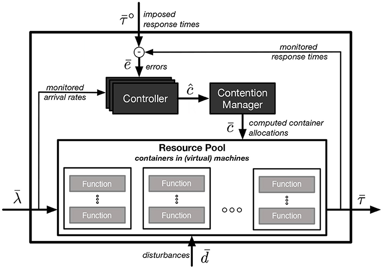
PAPS exploits a control-theoretic solution (Baresi et al., 2016) to scale containers deployed onto MEC nodes. It uses a dedicated controller for each deployed function f ∈ F (each function is deployed in one container). Figure 3 outlines a schematic view of the node-level control loop. We consider a discrete time, and define λf(k) as the monitored arrival rate of a function f at each control step k. is the vector of all the arrival rates of the functions. At control step k the amount of cores allocated to a function container is defined as cf(k) and is the vector of all the allocations. Disturbances are denoted by a vector of metrics that cannot be measured and/or controlled. The measured response time at each control step is collected for all the functions in vector , while denotes the vector of the desired response times (or set-points) for each function.
While the control system allows for varying , the current implementation of PAPS considers a constant desired response time for each function. These values should be set to a value lower than the actual SLA to avoid violations. For example, a reasonable target response time could be 0.8 * RTSLA, while lower values imply a more conservative approach and can be used for safety-critical applications.
cannot be calculated instantaneously but it should be aggregated over a set time window. The aggregation could be done by using different techniques that would not require a change in the control system. PAPS uses the average response time for computing , but more conservative aggregation functions (e.g., 99th percentile) could be used given the need of the application providers.
The node-level control loop employs a characteristic function (Υ) that defines the dynamics that govern the system, that is, how the response time changes given the monitored and controlled variables. We assume that this function be (i) dependent on the ratio between the allocated cores to the function (c) and the incoming arrival ratio λ (the higher the ratio, the lower the response time), (ii) monotonically decreasing toward an horizontal asymptote, which means that after a certain value of the aforementioned ratio the response time stop decreasing (e.g., when the degree of parallelism is completely exploited), and (iii) regular enough to be linearizable in the domain space of interest.
We found that a practically acceptable function is:
where parameters s1, s2, and s3 were obtained by profiling each function.
Given this model, PAPS exploits PI controllers as an effective mechanism to handle control systems dominated by first-order dynamics (Åström and Hägglund, 1995) (i.e., a system representable with first-order differential equations) such as the studied ones. Thus, PAPS executes the following control algorithm at each control step k for all deployed controllers:
where e is the error, the p subscript refers to variables computed in the previous time step (k − 1), Υ and Υinv correspond to the characteristic function and its inverse, respectively, α ∈ [0, 1) and p ∈ [0, 1) are the single pole of the controller and of the system, respectively, while xR is the state of the controller. The higher the value of α is, the faster the error converges to its steady state value (ideally to zero). On the other hand, if the value of α is too high, the allocation c could be too fluctuating. Kmax and Kmin are, respectively, the maximum and minimum allowed core allocations.
Within a MEC node, each controller oversees a single function/container and it is independent of the others (i.e., no synchronization is required). The computed allocations are collected in vector ĉ, which is not directly actuated since the sum of the allocation could be greater than the physical resource capacity of the MEC node. Instead, an additional control component, called contention manager, is in charge of computing a feasible allocation for all the functions () as:
Function solveContention down-scales the values in ĉ proportionally to the original allocation computed by the community-level control loop. However, other heuristics could be used to manage resource contention scenarios: for example one can easily prioritize safety-critical applications by using a weighted approach. Component contention manager is also in charge of updating the state of each controller (variable xRp) to make them consistent with the actuated allocations.
6. Experimental Evaluation
This section shows the prototype we implemented to materialize PAPS and a set of experiments that demonstrate the feasibility of the approach and its benefits.
6.1. Prototype
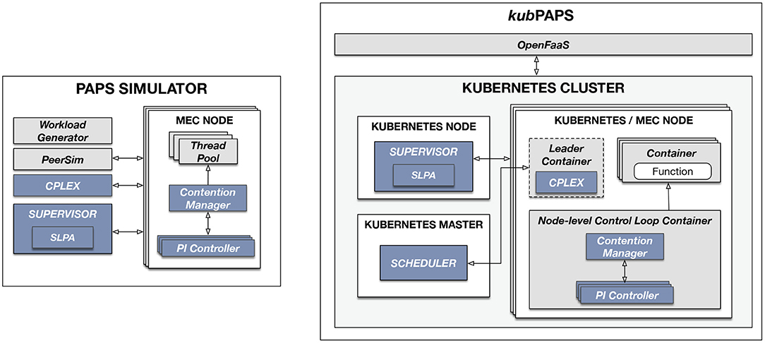
The prototype4 comprises two sub-systems as shown in Figure 4 (control-related components are shown in darker color). The first one is a simulator based on PeerSim5 that allows us to quickly and inexpensively test the implemented control strategies without the need of employing real resources. The second is kubPAPS, an implementation of PAPS that can be used to deploy the actual system and functions as in real-world edge topologies. kubPAPS is based on Kubernetes, a well-known container orchestrator, and Open-FaaS, a framework that integrates with Kubernetes and provides a serverless-like interface.
The simulator exploits PeerSim to implement the communication protocol that allows the control components and MEC nodes to exchange messages one another (e.g., to elect leaders, update communities, and actuate plans). To solve the optimization problem the simulator exploits the IBM CPLEX solver (v12.8). A MEC node is implemented as a set of dynamic pools of threads, where each pool is a container and a thread is one core.
The simulator also allows one to create different types of workloads and scenarios for each function deployed onto each MEC node. The execution time of a single function is randomly generated by using a normal distribution, while arrival rates are simulated by using three different scenario types (low, regular, and high) that are chosen randomly every 15 s to mimic an extremely fluctuating workload. Each of the three scenarios computes the time between two requests with an exponential distribution where, for example, scenario high is set with a lower value of the scale exponential parameter (the lower this value is the skewer the distribution is).
The users of kubPAPS can define function types and deploy them in the edge topology by using the OpenFaaS GUI that provides means to deploy applications in a serverless style. OpenFaaS extends Kubernetes by adding a set of APIs to manage functions that behind the scene operate with the Kubernetes cluster. PAPS itself reads the inputs sent to OpenFaaS and works directly with the Kubernetes API for managing the containers. Each MEC node is considered to be a Kubernetes node (e.g., in our test deployments we used Azure virtual machines as nodes).
The system-level control loop, deployed on a dedicated external node, expects a delay matrix where each value is the delay between two MEC nodes. The system-level-control loop reads this input and retrieves, using the Kubernetes API, the list of connected nodes. After checking that the nodes included in the matrix match the ones deployed in Kubernetes (i.e., the nodes in the matrix should be the same as the one running in the Kubernetes cluster), the SLPA algorithm is executed. Each node is then marked with two Kubernetes labels: COMMUNITY and ROLE. The former tags each node with the identifiers of the assigned communities, while the latter indicates if a node is the leader of a given community. This way, other components, or the system administrator, can access all the nodes of a community by simply using the Kubernetes API and retrieve the nodes filtered by label COMMUNITY. A dedicated container, which runs the CPLEX IBM solver, is deployed in the leader nodes which have the role of running the community-level control loop. The joint allocation-placement problem is solved periodically and the deployment of new containers is planned. This plan is sent to a dedicated custom Kubernetes scheduler that allows one to deploy the planned containers onto selected nodes.
Finally, the node-level control loop is implemented as additional container deployed onto each node. This container, which includes the PI controllers and contention manager, can reconfigure the containers running user functions. To do that, the node-level control loop uses a dedicated Kubernetes volume, an additional Kubernetes component that allows a container to communicate with the underlying file system or, as in this case, with the underlying container runtime (e.g., Docker6).
All the following experiments were run using the PAPS simulator deployed on two servers running Ubuntu 16.04 and equipped with an Intel Xeon CPU E5-2430 processor for a total of 24 cores and 328GB of memory. The maximum number of (simulated) containers that can be allocated onto a node depends on its memory capacity and the memory requirements of the functions that are to be deployed: 96GB and 128MB, respectively, in our experiments.
6.2. Partitioning
Our first experiments were dedicated to the partitioning algorithm. We tested the SLPA algorithm with multiple values for (i) the initial nodes (10, 20, 50, 100, 200, 500, 1, 000, 2, 000, and 5, 000), (ii) network delay threshold DMAX (0.1, 0.3, 0.5, and 0.7 s), and (iii) maximum community size MCS (10, 25, and 50). For each combination of these values, we built a matrix that contained the inter-node delays (δi,j) drawn from a uniform probability distribution [bounded to interval (0, 1)]. Each test was repeated ten times, and Figure 5 shows the resulting median values.

Figure 5. Execution times of partitioning phase when varying community size (A) and total number of nodes (B).
Figure 5A depicts the execution time (in logarithmic scale) of the algorithm with different values for and MCS. The results clearly show that the number of initial nodes significantly impacts the execution time that ranges from a few milliseconds with to 100 s with . On the other hand, the community size does not significantly affect the partitioning time and similar results are obtained with MCS equal to 10, 25 and 50. Figure 5B illustrates, instead, how the execution time changes when varying DMAX for different values of (x-axis adopts a logarithmic scale). For small networks ( < 100) the execution time is equal to a few milliseconds with different values of DMAX. When the size of the network increases the execution time becomes significantly higher: around 10 s with DMAX = 0.1 s, and more than 100 s with DMAX = 0.7 s. These results can be explained by the fact that higher delays mean a less restrictive possibility of partitioning, and thus the solution space is wider. Note that edge computing applications require low latency and thus DMAX should be even lower than 0.1 s. Moreover, the system-level control loop is supposed to only run when catastrophic events or significant failures happen, thus the obtained results seem quite reasonable for the analyzed problem.
6.3. Allocation, Placement, and Scaling
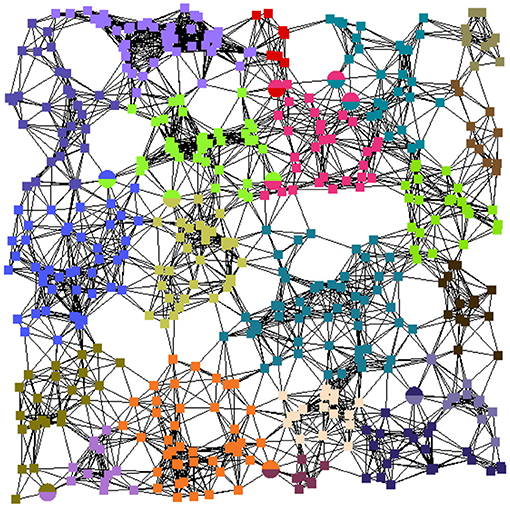
To evaluate the other control loops we used a large-scale edge topology of 250 nodes and normally distributed node-to-node latencies. We tested the allocation, placement, and scaling with different community sizes of 10, 25, and 50 nodes. Figure 6 exemplifies the resulting partitioning with communities of 25 nodes each. Equally-colored squares represent edge nodes within a single community; those that belong to overlapping communities are rendered with multi-color circles.
We exploited this setup to run two additional types of experiments to evaluate the feasibility and the scalability of PAPS, and to assess the benefits of having the node-level control loop —a key characteristic of our approach (see section 7). The first experiment, called testOPT, measured the system performance under an extremely fluctuating workload by only using the community-level control loop. This means that between two community-level decisions the resource allocation remains the same. The second, called testCT, added the node-level control loop that, instead, allocates resources dynamically with the goal of refining the initial configuration. The second experiment evaluates PAPS in its entirety.
For each of the three community sizes, we assessed PAPS with a different amount of function types: 50, 75, and 100. Each experiment used a simulation horizon of 10 min and tested one of the nine combinations of amount of function types and community sizes. For each of these combinations, we run 10 executions of testOPT and other 5 of testCT for a total of 180 experiments. The control periods of the community-level and node-level control loops were set to 1 min (maximum) and 5 s, respectively.
If no solution is computed by the community-level control loop within the minute, PAPS exploits a constraint-relaxed version of the optimization problem (described in section 4) and schedules the next community-level control loop after 1 min. As configuration parameters, we set the fraction of the marginal response time β and the value of the pole of the control theoretical planners to 0.5 and 0.9, respectively. The incoming traffic was generated by changing the workload scenario each 15 s as described in section 6.1. Finally, RTSLA was set to 120 ms for all the function types, and EMAX was set to 90 ms.
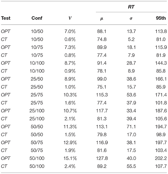
Table 1 reports the results obtained for experiments testOPT and testCT. Column Test shows the type of the experiment, column Conf reports the configuration used (e.g., 50/75 means that each community had 50 nodes and the number of function types was 75), V shows the percentage of SLA violations occurred in the experiment (e.g., 100% means that during the whole experiment the response time was above the SLA), and the last three columns report, respectively, the average (column μ), the standard deviation (column σ), and the 95th percentile (column 95th) of the response times in milliseconds (ms). All these data were calculated as average of the 10 repetitions executed for each test.
If we focus on testOPT, we can see that the community-level control loop is able to keep the violations always lower than 15.1%. The average response time is only higher (127.8 ms) than the SLA with configuration 50/100 where the combination of having a large community size, a high amount of function types to manage, and an extremely varying workload to handle makes the problem too complex for the community-level control loop alone. The reported standard deviation shows that that the average variation is always under 71 ms. The 95th percentile varies from 113.8 to 202.2 ms with configuration 10/50 and 50/100, respectively.
If we consider testCT, the maximum percentage of violations is 2.4%, almost one order of magnitude lower than testOPT. The average response time never reaches 100 ms, with a peak of 89.2 ms with configuration 50/100. The standard deviation (ranging from 5.2 to 55.5 ms) is always around half compared to the one obtain in testOPT with the same configuration, except for configurations 25/100 and 50/100 where testCT has a higher value than testOPT. The 95th percentile of the response time, which varies from 81.0 and 107.7 ms, is again lower than the one obtained by testOPT and never exceed the SLA.
The obtained results clearly show the advantages of having the node-level control loop. Solutions that require a large control period could result inefficient when dealing with highly varying workloads. The node-level control loop exploits lightweight control theoretical planners that do not require synchronization and can be used with control periods of 1 s or less. This way, containers can be dynamically reconfigured almost in real-time and precisely follow the curve of the workload.
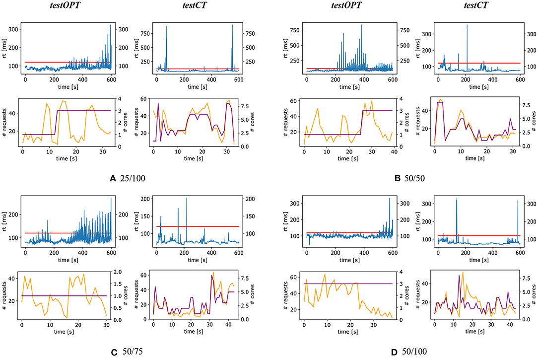
The charts of Figures 7, 8 help better visualize obtained results. These figures show four charts for each configuration: two charts on the left for testOPT and two on the right for testCT. For each test type and configuration, the chart positioned above the other shows the curve of response time (the horizontal line is the SLA) of the system during a single randomly selected repetition of the experiment; the chart positioned below shows the number of requests (lighter line) and the allocation (darker line) during the execution of a function on a single node.
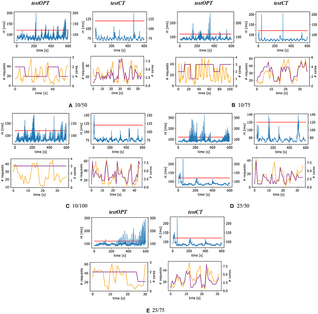
Figure 7. testOPT and testCT with configurations 10/50 (A), 10/75 (B), 10/100 (C), 25/50 (D), and 25/75 (E).
Figure 7A shows the results with configuration 10/50. The response time measured in testOPT is more fluctuating than the one of testCT, and while in testOPT the SLA is violated multiple times, in testCT there is one single peak of almost 140 ms around 450 s. If we compare the charts about the workload we can clearly see how the node-level control loop helps follow the workload more precisely (i.e., the light and dark curves have a similar trend), while a resource allocation only based on the outputs of the community-level control loop appears to be far from the optimal in many cases. For example, the workload (light line) for the depicted (randomly selected) function has some peaks between 15 and 40 s. For this reason, the community-level control loop raises the allocation from 1 to 2 cores, however after 40 s the workload decreases and the allocation remains sub-optimal.
Another paradigmatic example can be seen in Figure 8B that shows the results for configuration 50/50. In this case, testCT presents some more violations with respect to the previous scenario, but the response time is almost always (coherently with what is reported in column 95th of Table 1) below the SLA. On the other hand testOPT shows different SLA violations and the resource allocation does not fit the actual workload.
7. Related Work
Edge computing is considered one of the key enablers of smart and sustainable cities (Jararweh et al., 2020; Khan L. U. et al., 2020; Khan Z. et al., 2020) and many kinds of applications related to smart cities can exploit edge infrastructures to provide urban users with intelligent services such as autonomous vehicles (Ning et al., 2019), building energy management (Liu et al., 2019) and crowd routing (Zhao et al., 2019). PAPS handles the management of edge infrastructures, which is considered one of the open challenges of the field (Khan L. U. et al., 2020).
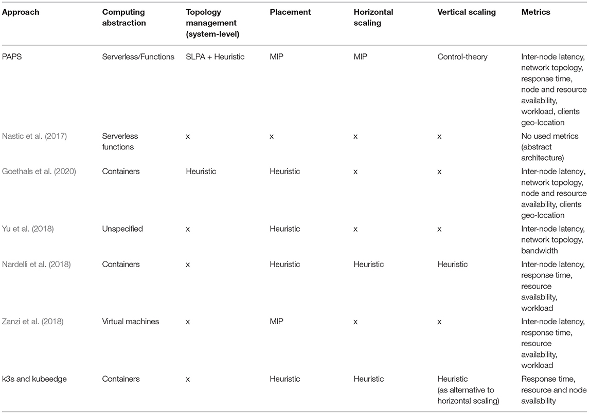
Some relevant works in the literature focus on the efficient management of edge computing topologies. Our previous work (Baresi et al., 2019b) proposes a framework for the opportunistic deployment of serverless functions onto heterogeneous executors at the edge. However, the framework does not handle the allocation and placement problems across MEC nodes.
Nastic et al. (2017) present a reference architecture for the development and execution of functions dedicated to data analysis at the edge. The architecture exploits a centralized orchestrator that receives a contract, which defines the QoS goals to fulfill and the corresponding management policy to operate. Compared to PAPS, this work provides an abstract overview of the system, it does not provide a concrete realization of the architecture and the management mechanisms are delegated to external users.
Goethals et al. (2020) propose Swirly, an approach for the real-time management of large-scale edge topologies. Swirly, as PAPS, considers the scalability of the management solution at the edge given the huge amount of nodes, applications, and virtualized resources involved. Swirly focuses on application placement onto edge nodes by taking into account the latency between nodes and the capacity of the infrastructure. Moreover, Swirly handles changes in the network topology and in the communication latency. Experiments show that Swirly can efficiently manage thousands of edge devices. Compared to PAPS, Swirly considers fixed resource allocation while our solution dedicates the node-level control loop to that. Our evaluation shows the benefit of this additional control loop.
Yu et al. (2018) describe an approach for the placement and routing problems for QoS-aware applications at the edge. Their formulation considers multiple workload sources and its (approximated) solution has polynomial complexity. Compared to PAPS, they limit an application to be single instance (i.e., not replicated) and they do not consider the (dynamic) allocation of resources, which is key for edge systems characterized by highly volatile workloads.
Nardelli et al. (2018) propose an approach for the deployment and resource allocation of containerized applications at the edge. This solution, among all, is the most similar to PAPS since it provides smart placement and both horizontal and vertical auto-scaling. Their problem formulation is defined by means of Integer Linear Programming and it is NP-hard. Thus, they use greedy, sub-optimal algorithms to solve the problem in reasonable time. Compared to PAPS, their solution does not provide any management at the system-level (no partitioning or failure resistance). Moreover, their approach is not hierarchical and they compute the next placement and horizontal and vertical allocations in a single step. However, placement requires a lower frequency than scaling since the migration of an application is a critical task. We advocate that the solution embedded in PAPS can better handle the complexity of this domain. The system-level adaptation is slow and is only activated in case of critical events. The Edge topology is split in small, low latency communities so that it is feasible to find an optimal application placement with our MIP formulation. Finally, to handle the highly variable workload we employ extremely fast control-theoretical planners that perform vertical scaling for running applications at the node-level. Re-configuring the resource allocated to a running application is not a critical operation and can safely be done at a very fast rate.
Zanzi et al. (2018) propose a multi-tenant resource orchestration approach for systems that adhere to the MEC model. The authors introduce the concept of MEC broker, a component that is in charge of granting tenants (prioritized by their privilege level) access to resources. The proposed system optimizes the placement of application components onto dedicated nodes for users with higher priority, or onto shared nodes according to resource availability and network latency. PAPS exploits the same MEC model but employs a serverless architecture, takes into account the SLA of each function, and can cope with highly-variable fluctuations of workloads by exploiting control theoretical planners.
A number of other works (Bahreini and Grosu, 2017; Li and Wang, 2018; Ouyang et al., 2018; Wang et al., 2019; Salaht et al., 2020) focus on the problem of placing applications on geo-distributed topologies. The combinatorial nature of this problem makes optimal solutions nearly unfeasible to find (NP-Hard problems) (Yu et al., 2018). Existing solutions often employ heuristics and approximations, are often validated for a limited number of nodes and applications, and usually do not consider allocating and scaling resources dynamically as PAPS does. We conceived our solution with the goal of targeting scalability and the management of unpredictable workloads specifically as first class requirements. PAPS employs a hierarchical control strategy that reduces the complexity of the placement by partitioning the original topology and highly fluctuating workloads are tackled by means of control theoretical planners in real time.
As for industrial tools, k3s7 and kubeedge8 provide a distribution of Kubernetes dedicated to edge computing. In essence, these tools simplify the deployment of Kubernetes on resource constrained devices (e.g., Raspberry PIs) and provide means to distinguish beween and connect edge and cloud nodes without changing the original Kubernetes API. These tools rely on Kubernetes existing components for the management of the resources. Kubernetes does not provide any dedicated means to manage an edge topology (e.g., no partitioning) and does not consider the inter-delay between nodes as PAPS and some of the described approaches in the literature do. Kubernetes provides a scheduler for the placement of containers that, by default, only considers the resource availability of nodes (containers are assumed to have a fixed resource allocation). As for resource allocation, Kubernetes provides two auto-scaling systems: the Horizontal Pod Autoscaler (HPA) and the Vertical Pod Autoscaler (VPA). These scaling systems allow users to set a desired target value for a metric (e.g., response time) and exploit a heuristic that computes the new allocation proportionally to the difference between the target value and the measured one. However, HPA and VPA cannot work together and VPA requires containers to be rebooted to be reconfigured thus adding extra latency to the process.
Table 2 shows a detailed summary of the different examined approaches by focusing on computing abstractions, techniques for adaptation actions, and metrics used to carry out the control. PAPS has a holistic view of the system and adapts each conceptual level (the full edge topology, communities and nodes) in a dedicated and optimized way. Other approaches provide a partial adaptation and only focus on certain aspects: as shown in column metrics, PAPS exploits the richest set of data to control the system. Most of the solutions employ heuristics, to limit the resolution time of expensive optimization problems, at the cost of providing less precise solutions. PAPS solves this problem by partitioning the topology in communities that are small enough to compute optimal placements in reasonable times. Fast PI controllers provide adaptation at the node-level with a control period of a few seconds. However, compared to heuristics, this does not come at the cost of scarifying formal guarantees that control-theory provides. Finally, while most of the solutions focus on containers, PAPS exploits the serverless paradigm that facilitates users, when they deploy applications, by completely hiding the underlying infrastructure (containers, VMs, or physical machines).
8. Conclusions
This paper presents PAPS, a system for the management of large-scale edge topologies. PAPS exploits the serverless computing model and employs a hierarchy of three control loops. At the system-level it partitions the edge topology into smaller, delay-aware communities which are, in turn, managed by an elected leader. The community leader is responsible for allocating and placing containers into the edge nodes according to the incoming workload and the desired response time. Finally, at the node-level, control-theoretical planners are in charge of refining the initial allocation by vertically scaling containers in almost real-time. The paper also describes a prototype of PAPS composed of two sub-systems: a simulator that was used to run the empirical assessment and an extension of Kubernetes and OpenFaaS for real-world deployment. The reported experiments show the feasibility of the approach, its performance under extremely fluctuating workloads, and highlights the benefit of the multi-level solution.
Data Availability Statement
The original contributions presented in the study are included in the article/supplementary material, further inquiries can be directed to the corresponding author/s.
Author Contributions
LB supervised the work, participated in the writing, and co-directed the research line. GQ participated in the implementation of the work and its assessment, participated in the writing, and co-directed the research line. All authors contributed to the article and approved the submitted version.
Funding
This work has been partially supported by the SISMA national research project, which has been funded by the MIUR under the PRIN 2017 program (Contract 201752ENYB) and by the European Commission grant no. 825480 (H2020), SODALITE.
Conflict of Interest
The authors declare that the research was conducted in the absence of any commercial or financial relationships that could be construed as a potential conflict of interest.
Acknowledgments
This work would have not been possible without the precious work of Danilo Filgueira Mendonca. We also thank Oscar Pindaro and Fabio Losavio for their work on the SLPA algorithm.
Footnotes
3. ^The amount of allocated memory is fixed and defined in the function type descriptor as explained is section 2.
4. ^Source code available at: https://github.com/deib-polimi/PAPS
References
Åström, K. J., and Hägglund, T. (1995). PID Controllers: Theory, Design, and Tuning, Vol. 2. Raleigh, NC: Isa Research Triangle Park.
Bahreini, T., and Grosu, D. (2017). “Efficient placement of multi-component applications in edge computing systems,” in Proceedings of the Second ACM/IEEE Symposium on Edge Computing (San Jose, CA), 1–11.
Baldini, I., Castro, P., Chang, K., Cheng, P., Fink, S., Ishakian, V., et al. (2017). “Serverless computing: current trends and open problems,” in Research Advances in Cloud Computing (Singapore: Springer), 1–20.
Baresi, L., Guinea, S., Leva, A., and Quattrocchi, G. (2016). “A discrete-time feedback controller for containerized cloud applications,” in Proceedings of the 2016 24th ACM SIGSOFT International Symposium on Foundations of Software Engineering (Seattle, WA: ACM), 217–228.
Baresi, L., Mendonça, D. F., Garriga, M., Guinea, S., and Quattrocchi, G. (2019b). A unified model for the mobile-edge-cloud continuum. ACM Trans. Internet Technol. 29, 1–21. doi: 10.1145/3226644
Baresi, L., Mendonça, D. F., and Quattrocchi, G. (2019a). “PAPS: a framework for decentralized self-management at the edge,” in International Conference on Service-Oriented Computing (Cham: Springer), 508–522.
Bernstein, D. (2014). Containers and cloud: from lxc to docker to kubernetes. IEEE Cloud Comput. 1, 81–84. doi: 10.1109/MCC.2014.51
Dustdar, S., Guo, Y., Satzger, B., and Truong, H.-L. (2011). Principles of elastic processes. IEEE Internet Comput. 15, 66–71. doi: 10.1109/MIC.2011.121
Felter, W., Ferreira, A., Rajamony, R., and Rubio, J. (2015). “An updated performance comparison of virtual machines and linux containers,” in 2015 IEEE International Symposium on Performance Analysis of Systems and Software (ISPASS). (Philadelphia, PA: IEEE), 171–172.
Goethals, T., De Turck, F., and Volckaert, B. (2020). Near real-time optimization of fog service placement for responsive edge computing. J. Cloud Comput. 9, 1–17. doi: 10.1186/s13677-020-00180-z
Jararweh, Y., Otoum, S., and Ridhawi, I. A. (2020). Trustworthy and sustainable smart city services at the edge. Sus. Cities Soc. 62:102394. doi: 10.1016/j.scs.2020.102394
Khan, L. U., Yaqoob, I., Tran, N. H., Kazmi, S. M. A., Dang, T. N., and Hong, C. S. (2020). Edge-computing-enabled smart cities: a comprehensive survey. IEEE Internet Things J. 7, 10200–10232. doi: 10.1109/JIOT.2020.2987070
Khan, Z., Abbasi, A. G., and Pervez, Z. (2020). Blockchain and edge computing-based architecture for participatory smart city applications. Concurrency Computat. 32:e5566. doi: 10.1002/cpe.5566
Li, Y., and Wang, S. (2018). “An energy-aware edge server placement algorithm in mobile edge computing,” in 2018 IEEE International Conference on Edge Computing (EDGE) (San Francisco, CA: IEEE), 66–73.
Liu, Y., Yang, C., Jiang, L., Xie, S., and Zhang, Y. (2019). Intelligent edge computing for iot-based energy management in smart cities. IEEE Netw. 33, 111–117. doi: 10.1109/MNET.2019.1800254
Lloyd, W., Ramesh, S., Chinthalapati, S., Ly, L., and Pallickara, S. (2018). “Serverless computing: an investigation of factors influencing microservice performance,” in 2018 IEEE International Conference on Cloud Engineering (IC2E) (Orlando, FL), 159–169.
Mach, P., and Becvar, Z. (2017). Mobile edge computing: a survey on architecture and computation offloading. IEEE Comm. Surveys Tutorials 19, 1628–1656. doi: 10.1109/COMST.2017.2682318
Nardelli, M., Cardellini, V., and Casalicchio, E. (2018). “Multi-level elastic deployment of containerized applications in geo-distributed environments,” in 2018 IEEE 6th International Conference on Future Internet of Things and Cloud (Barcelona). 1–8.
Nastic, S., and Rausch, T. (2017). A serverless real-time data analytics platform for edge computing. IEEE Internet Comput. 21, 64–71. doi: 10.1109/MIC.2017.2911430
Ning, Z., Wang, X., and Huang, J. (2019). Mobile edge computing-enabled 5g vehicular networks: Toward the integration of communication and computing. IEEE Vehicular Technol. Mag. 14, 54–61. doi: 10.1109/MVT.2018.2882873
Ouyang, T., Zhou, Z., and Chen, X. (2018). Follow me at the edge: mobility-aware dynamic service placement for mobile edge computing. IEEE J. Selected Areas Commun. 36, 2333–2345. doi: 10.1109/JSAC.2018.2869954
Roberts, M. (2018). Serverless Architectures. Available online at: https://martinfowler.com/articles/serverless.html
Salaht, F. A., Desprez, F., and Lebre, A. (2020). An overview of service placement problem in fog and edge computing. ACM Computi. Surveys 53, 1–35. doi: 10.1145/3391196
Satyanarayanan, M. (2017). The Emergence of edge computing. Computer 50, 30–39. doi: 10.1109/MC.2017.9
Several authors (2019). Mobile Edge Computing (mec); Framework and Reference Architecture. Technical report, ETSI GS MEC.
Shi, W., Cao, J., Zhang, Q., Li, Y., and Xu, L. (2016). Edge computing: vision and challenges. IEEE Internet of Things J. 3, 637–646. doi: 10.1109/JIOT.2016.2579198
Shi, W., and Dustdar, S. (2016). The promise of edge computing. Computer 49, 78–81. doi: 10.1109/MC.2016.145
Wang, S., Zhao, Y., Xu, J., Yuan, J., and Hsu, C.-H. (2019). Edge server placement in mobile edge computing. J. Parallel Distributed Comput. 127, 160–168. doi: 10.1016/j.jpdc.2018.06.008
Weyns, D., Schmerl, B., Grassi, V., Malek, S., Mirandola, R., Prehofer, C., et al. (2013). “On patterns for decentralized control in self-adaptive systems,” In Proceedings of the Software Engineering for Self-Adaptive Systems II: International Seminar (Berlin; Heidelberg: Springer), 76–107.
Xie, J., Szymanski, B. K., and Liu, X. (2011). “Slpa: uncovering overlapping communities in social networks via a speaker-listener interaction dynamic process,” in Proceedings of the 11th IEEE Int. Conf. on Data Mining Workshops (Vancouver, BC), 344–349.
Yu, R., Xue, G., and Zhang, X. (2018). “Application provisioning in FOG computing-enabled internet-of-things: a network perspective,” in Proceedings of the 37th IEEE International Conference on Computer Communications, INFOCOM (Honolulu, HI), 783–791.
Zanzi, L., Giust, F., and Sciancalepore, V. (2018). “M2ec: a multi-tenant resource orchestration in multi-access edge computing systems,” in Proceedings of the 19th IEEE Wireless Communications and Networking Conference, WCNC, 1–6.
Keywords: edge computing, serverless, function as a service, runtime management, resource allocation, control theory, containers
Citation: Baresi L and Quattrocchi G (2021) PAPS: A Serverless Platform for Edge Computing Infrastructures. Front. Sustain. Cities 3:690660. doi: 10.3389/frsc.2021.690660
Received: 03 April 2021; Accepted: 04 June 2021;
Published: 15 July 2021.
Edited by:
Antonio Puliafito, University of Messina, ItalyReviewed by:
Andrea Passarella, Italian National Research Council, ItalyFrancesco Lo Presti, University of Rome Tor Vergata, Italy
Copyright © 2021 Baresi and Quattrocchi. This is an open-access article distributed under the terms of the Creative Commons Attribution License (CC BY). The use, distribution or reproduction in other forums is permitted, provided the original author(s) and the copyright owner(s) are credited and that the original publication in this journal is cited, in accordance with accepted academic practice. No use, distribution or reproduction is permitted which does not comply with these terms.
*Correspondence: Giovanni Quattrocchi, Z2lvdmFubmkucXVhdHRyb2NjaGlAcG9saW1pLml0
 Luciano Baresi
 Giovanni Quattrocchi