 Craig W. Hogle*‡
 Ashlyn D. Burch‡
 Jonathan D. SterkMatthew N. H. Chow
 Megan IvoryDaniel S. Lobser
 Peter Maunz†Jay Van Der WallChristopher G. YaleSusan M. ClarkDaniel StickMelissa C. Revelle
- Sandia National Laboratories, Albuquerque, NM, United States
Excess micromotion can be a substantial source of errors in trapped-ion based quantum processors and clocks due to the sensitivity of the internal states of the ion to external fields and motion. This problem can be fixed by compensating background electric fields in order to position ions at the RF node and minimize their driven micromotion. Here we describe techniques for compensating ion chains in scalable surface ion traps. These traps are capable of cancelling stray electric fields with fine spatial resolution in order to compensate multiple closely spaced ions due to their large number of relatively small control electrodes. We demonstrate a technique that compensates an ion chain to better than 5 V/m and within 0.1 degrees of chain rotation.
1 Introduction
Trapped ions are a leading candidate for quantum information systems due to their long coherence times and low gate errors (Ballance et al., 2016; Gaebler et al., 2016). Typically, a quadrupole trap is used to confine ions in three dimensions using a combination of oscillating and static electric fields (otherwise known as a pseudopotential well). One of the most precise and scalable ways to fabricate this type of trap is to lithographically define the electrodes on a planar surface (Seidelin et al., 2006; Moehring et al., 2011; Romaszko et al., 2020). In both surface and 3D ion traps, the oscillating nature of the trapping potential leads to ion motion at the RF drive frequency beyond its harmonic motion, known as micromotion. Additionally, stray background electric fields or imperfections in the voltage control modeling or trap fabrication can distort the shape of the potential well or offset the ion from the RF node leading to excess micromotion. This can have a detrimental effect on spectral line shapes and cause second-order Doppler shifts (Berkeland et al., 1998), decrease ion lifetimes (DeVoe and Brewer, 1996), cause laser damping instability in chains (DeVoe et al., 1989), and induce ion heating that leads to decoherence (Poyatos et al., 1998). Both ion based quantum computers and atomic clocks are prone to errors from these effects, and in some cases, they are the leading source of uncertainty (Chou et al., 2010; Arnold et al., 2015).
Because micromotion is a common problem in trapped ion systems, it is a well-studied phenomenon. Numerous methods exist for detecting and quantifying it, including micromotion sideband spectroscopy (Berkeland et al., 1998), RF correlation measurements (Roos, 2000), ‘synchronous’ tickle measurements (Eltony, 2010), ‘chirp’ tickle measurements (Clark et al., 2021), parametric resonance detection (Ibaraki et al., 2011), and using high-finesse optical cavities as spectrum analyzers for ion-cavity emissions (Chuah et al., 2013). As more ions are needed to support more complicated quantum algorithms, research groups have begun exploring the feasibility of utilizing chain lengths with up to 100 ions (Pagano et al., 2019). However, standard micromotion detection methods become increasingly complicated with advancing trap designs and greater ion numbers, due to shrinking mode spacing and growing complexity of optical addressing and control of individual ions. Having complete and precise control over the voltages applied to the electrodes is necessary for detecting and compensating micromotion in these long ion chains using these techniques, as tilts in the chain can inhibit finding the micromotion minimum simultaneously for each ion. Here, we describe a technique for generating the voltages that are applied to each control electrode to compensate a chain of ions and can correct for chain misalignment from the RF node.
Surface ion traps provide an ideal platform for compensating significant numbers of ions due to the low ion height and segmented control electrodes that yield fine spatial resolution. While correcting for stray electric fields may be necessary in all three spatial dimensions (radial and axial), we are most concerned about micromotion in the radial directions in linear traps (in use here, discussed in Section 2), thus we ignore any possible axial pseduopoential as it is small in these traps. This is not necessarily negligible in other systems such as multi-ion optical clocks, where axial micromotion can cause increased heating rates and ion loss, and it can be a challenge to compensate (Keller et al., 2019). In many cases, trap imperfections, surface effects, or stray fields can introduce tilts into the chain with respect to the RF node (Harlander et al., 2010; Allcock et al., 2012). Here, we explore how our voltage solutions enable chain rotations (shown in Figure 1) which compensate for this tilt while minimizing micromotion.
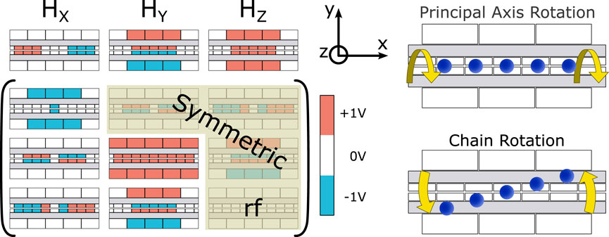
Figure 1. This schematic reflects the construction of the voltage solutions. The offset fields depicted at the top (Hx, Hy, and Hz) are used for compensating the ions to the RF potential node. The first term along the diagonal of the Hamiltonian is Haxial, and Hradial corresponds to the second term along the diagonal. The solutions only need the five non-highlighted curvature terms of the matrix due to symmetry, and the final term is no longer needed because Htrace sums the terms along the diagonal. Though the colored electrodes are not the real voltages applied to our electrodes at a given time, the positive and negative values are depicted to aid the understanding of each term’s contribution. The two rotations relevant to results discussed in Section 3 are shown on the right: a principal axes around the x-axis and a rotation of the chain around the z-axis.
2 Materials and methods
The ability to minimize micromotion on a chain of ions is made possible by a unique technique for 1) calculating voltage solutions, which are the arrays of voltages we apply to the control electrodes that confine ions axially and position them on the RF node, and 2) our ability to measure the local micromotion minimum. In this work, using this voltage solution framework, we show that we can minimize the micromotion in a 5 ion chain by using a set of basis functions to offset and rotate the chain, correcting for any uncompensated electric fields in the radial direction with zero- and first-order spatial dependence over the ion chain. Most of the standard micromotion detection techniques aforementioned are applicable for detecting ion motion parallel to the direction of laser propagation; in our surface trap, the optical access is constrained to one radial direction, so we utilize a technique that is largely insensitive to this geometry - micromotion sideband spectroscopy verified with parametric resonance experiments - to minimize micromotion along an entire rotated chain. In this section, we explain how we generate our voltage solutions and detail the micromotion techniques we employed.
2.1 Voltage solutions
In our experiments, we use a linear microfabricated surface ion trap, the Phoenix trap (Revelle, 2020). A pair of long rails provide RF voltage for confinement in the two radial directions, orthogonal to the rails. Static DC voltages are applied to the segmented electrodes which provides axial confinement, along the RF rail. We define our coordinate system with the x-axis along the linear axis of the trap, y is parallel to the surface in the radial direction, and z is normal to the surface of the trap, as shown in Figure 1. At a desired trapping location we approximate the total potential as a 3D quadratic potential whose surfaces of constant potential form ellipsoids. Such a quadratic potential can be described by a real symmetric curvature tensor, Vij, where i, j ∈ x, y, z. Under this approximation (and taking the desired single-ion equilibrium position to be the origin without loss of generality), the total potential as a function of the position r is
where the linear field offsets Ei and curvature Vij are functions of the voltage configuration.
A single voltage solution that provides a desired field offset and curvature can be determined through a constrained least squares optimization (Blakestad et al., 2011). Specifically, for a desired set of field offsets and curvatures encoded in a vector
Here, M is the linear transformation that maps a voltage configuration to field offsets and curvatures and v is the base voltage solution. In order to provide full dynamic control over the offset and the curvature, we seek a set of voltage solutions v(k) for k = 1, … , n that provide a unit change in these n independent degrees of freedom. That is, we seek an effective map M−1 so that for each component of
The field offsets and curvatures are encoded in
Given the encoding of the field offsets and curvatures, we now seek to generate a set of base voltage solutions v(k) for k = 1, … , 9, such that each solution maps to a single component of
Given these base solutions v(k) that map to the individual components of the vector
To perform rotations of ion chains, the potential can be dynamically, arbitrarily, and precisely reshaped by changing gk to any of the traceless components that map onto the curvature tensor. The level of control these solutions afford is crucial for implementing very precise rotations, especially for longer chains of ions. If, for example, a compensated chain of 32 171Yb+ ions spaced by 5 μm each is rotated by 0.1° about the center of the chain along the x-axis, the ions at the end will be off the RF node by 0.13 μm, corresponding to an 85 V/m field in a trap with 3 MHz radial frequencies.
2.2 Micromotion compensation
To compare the effect of these solutions, this experiment uses a chain of 171Yb+ ions in a Sandia-fabricated linear surface trap, the Phoenix trap (Revelle, 2020). The region on the trap designated for quantum operations is 1.5 mm long with segmented control electrodes outside the RF rails (primarily for rotation) and segmented control electrodes that are inside the RF rails and 10 μm offset below the surface metal to increase the confinement at the ion. Using the solutions described in the previous section, the ions are trapped 68 μm from the surface in the quantum region and confined with single-ion secular frequencies of 1.7 MHz, 1.8 MHz radially and 0.4 MHz axially. Doppler cooling is achieved using 369 nm light to excite transitions between the 2S1/2 and 2P1/2 states, with state detection using a closed cycling transition (Clark et al., 2021). We load up to 5 ions and can rotate the principal axes of the confinement about x by up to 90° by changing the gain on each of the five traceless terms from Section 2.1. As the principal trap axes are rotated about x (see Figure 1), the radial motional modes rotate away from their original orientations aligned with the y and z-axes. To minimize the micromotion, we adjust the offset fields along the y-axis and z-axis, and the chain is rotated by changing the voltage gain on the rotation terms for the two trap axes Hyz and Hxz (with mixed contributions from the other remaining terms).
First, we demonstrate micromotion compensation utilizing resolved sideband measurements, a sensitive technique that detects ion motion (but only in the direction of the laser). Here, we drive the hyperfine clock state in 171Yb+ using a 355 nm pulsed laser two photon Raman transitions via a virtual state that is detuned between the 2P1/2 −2P3/2 level (Berkeland et al., 1998). By detuning from the clock transition by the RF drive frequency ΩRF, which in this case is 2π × 36.3 MHz, we probe the micromotion sideband directly. The height of this peak is determined by the Rabi rate and the induced motion of the ion. We scan across the transition frequency of the Raman beams, using a Gaussian fit to measure the transition frequency and the strength of the response. The height is compared for various values of the offset terms Hy and Hz. The peak heights can then be plotted versus the applied voltage to determine which field offsets correspond to the minimum peak height. An example of this measurement on one ion is shown in Figure 2, where the blue curves show their respective y and z offset corrections.
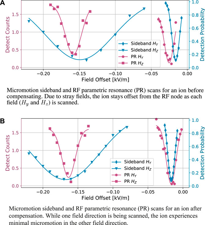
Figure 2. Measurements using RF parametric resonance and Raman sideband spectroscopy techniques prior to (A) and post (B) compensation. The techniques measure micromotion relative to an applied electric field offset, known as a shim field. The field offset can be used as a correction such that the ion is restored to the RF node. We fit the region of interest to a phenomenological model, an inverse Gaussian, to find the respective minima. The two methods sample different projections of the micromotion, which leads to the differences in the minima observed in part (A) However, both methods can be used to minimize the negative effects due to micromotion and both methods result in the same respective compensation field (as shown in part (b)).
We verify our resolved sideband measurements with a parametric resonance technique. The Doppler cooling light is detuned from the resonant frequency by ΩRF. While cooling the ion, an additional RF frequency is added to the RF electrodes (typically using an RF coupler) that resonates with the ion’s motion and displaces the ion further from equilibrium. The increase in ion motion causes an increase in the detuned detection signal due to the resulting Doppler shift. Thus a peak can be observed when the additional drive frequency is equal to the secular frequency (Ibaraki et al., 2011). The peak of this detuned signal can be compared to various applied RF fields, increasing in fluorescence as the ion is pulled further away from the RF node. As in the previous method, we use the field offset terms Hy and Hz to minimize the height and compensate the ion, comparing across different offset field values. An example of using this technique on one ion is also shown as the red curves in Figure 2.
These two methods rely on different lasers (Raman vs Doppler) which have different angles with respect to the RF axis resulting in slightly differing values of the measured micromotion which is sensitive to the laser propagation. However, both methods result in similar compensation fields, which is shown in Figure 2B, demonstrating that either method can be an effective tool in minimizing micromotion. Parametric resonance scans have been shown to be reliable in probing out of plane micromotion without direct laser access, due to the direct parametric excitation of the motion (Ibaraki et al., 2011). Resolved sideband measurements, though requiring laser overlap in the motional direction, result in the same compensation values, showing it can be an equally effective tool, but faster than and less prone to ion loss than the parametric scan. In the unfortunate case where there are out-of-phase RF fields in the experiment, the parametric resonance approach will only place the ion at a pseudopotential minimum while the resolved sideband approach minimizes micromotion, so there could be slightly different compensation points. However, in the case where there is no RF pickup on the compensation electrodes or spatially-dependent noise sources (the likely source of ion chain tilt here), these two approaches result in the same compensation minima, as is the case for these measurements. A full analysis of different micromotion methods, including those we use in experiments here, and their ion position resolution can be found in (Eltony, 2010).
3 Results: Compensation of a rotated ion chain
In the case of ion chains, stray fields can have a complex effect on the individual ion positions. Our voltage solutions enable us to minimize the micromotion across an entire chain, while correcting for offsets and rotations, thus mitigating some of these effects. Though the parametric resonance technique described in Section 2.2 directly probes the motional sidebands, it can be time consuming to implement and a principal axis rotation is required. Additionally, a chain of ions has a dense secular frequency mode structure that makes driving a specific mode more challenging and can lead to exciting ions out of the trap. We, therefore, use the parametric resonance measurements only for validation but show full radial micromotion compensation on a chain of five ions using resolved sideband spectroscopy for different rotations of principal axes, thus showing that any amount of overlap with the laser propagation allows for this method to be useful.
Figure 3 demonstrates the use of micromotion compensation in a chain of 5 ions, and using resolved sideband spectroscopy, and based on the data, we measure a slight tilt in the ion chain with respect to the chain axis. As seen in Figure 3A, at a principal axis rotation of 15°, we first probe the micromotion sideband and find the relative excitation of each of the ions at a particular Hy offset. The height of these peaks are then compared at different Hy offset fields as depicted in Figure 3B in order to find a minima in the excitation for each ion. Ideally, all ions’ micromotion should be minimized at one local field offset minimum and remain at that same local minimum regardless of the specified principal axis rotations. However, as seen in Figure 3B, we see a break in this symmetry, leading to the conclusion that there is a tilt in the chain.
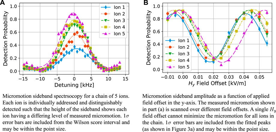
Figure 3. 5 ion compensation data for a 15° principal axis rotation. Part (A) shows micromotion sideband peaks for a chain of five ions at a particular shim field in the y-direction. This scan is performed at various shim values as shown in Part (B). This shows an example scan where each ion’s micromotion sideband peak is not minimized at the same shim value, indicating a rotation along the chain of ions. The Hy Field offset (from part b) can be fit with uncertainties less than 1 V/m.
Using the voltage solutions described in Section 2.1, we demonstrate precise control over the chain rotation and repeat these measurements at different chain rotation angles until all ions’ micromotion minima occur at the same value of applied field offset. Figure 4 demonstrates this technique for two different principal axes rotations, each one requiring a different rotation angle to reach an overlap of each ion’s potential. At 5° of principal axis rotation in Figure 4A, the ions measure best overlap at −0.4° chain rotation, which corresponds to a 0.008 kV/m Hy offset field correction. Likewise, at a 15° principal axis rotation in Figure 4B, the point of best overlap is at 0.4°, requiring 0.013 kV/m Hy offset field correction. Despite the fact that our experiment requires different sets of compensating offset fields for two different principal axis rotations, this discrepancy is not an issue for most ion trap experiments since the principal axis usually stays fixed. One could argue that because the field offsets are different for different principal axes rotations, we have not fully corrected for the tilt in the chain. However, we suspect that the discrepancy may be due to an error in the eigenvalues for g(k). If the applied ωi do not match the measured secular frequencies, then there may be residual trace resulting in a rotation that impacts other factors of the potential. Another source of the discrepancy may found on the hardware-level, whether that be from fabrication imperfections or imperfect voltages applied to the electrodes. In this case, the necessary micromotion compensation correction would add a unique offset to the needed rotation angle for each principal axis rotation. Additionally, there could be an error in the calibration that results in an over- or under-rotation of the chain; however, this is unlikely as principal axis solutions are symmetric about the axis of the ion chain. The overall slope of the fits in Figure 4 is likely due to a stray field along the x-axis, and could be minimized with compensation in that direction. Though micromotion compensation is more commonly used to correct for various background electric fields, the added level of precise control from our unique set of voltage solutions allows us to correct for the tilt in the chain caused by stray fields as well as other anomalous effects.
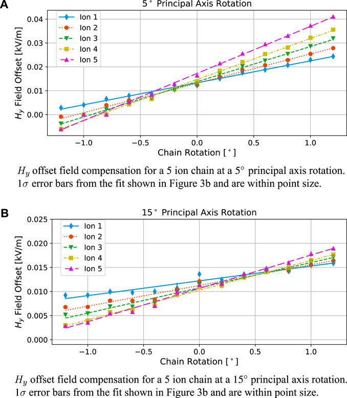
Figure 4. 5 ion chain compensation data. The micromotion sideband measurements shown in Figure 3 are scanned over chain rotations performed around the z-axis. Correcting for small rotations in the chain allow for a single Hy field offset to minimize the micromotion (correcting for a tilt of the chain due to background fields). This was performed at both a 5° principal axis rotation Panel (A) and a 15° principal axis rotation Panel (B). The optimal chain rotation is determined using the mean intersection of the linear fits, and thus the necessary compensation rotations are determined as −0.4° and 0.4° for a 5° and 15° principal axis rotation, respectively.
4 Discussion
While employing resolved sideband spectroscopy, and verifying our results with parametric resonance measurements, we demonstrate that a chain of five ions can be compensated within 0.1° rotation with a single applied field correction based on the uncertainty between the linear fits, minimizing the micromotion of all five ions. This ability to rotate the chain with such precision affords the simultaneous compensation of field offsets. With trapped ions as one of the leading quantum computing platforms, it is important to have the voltage control and stability over ion chains of increasing length, as more qubits are needed to realize quantum advantage (Grover, 1996; Shor, 1997). However, up to this point, there have been no reported methods that create a voltage control necessary to manipulate ion chains while simultaneously efficiently measuring and compensating for micromotion. Surface ion traps in particular provide a platform that allows for large numbers of electrodes and therefore requires higher levels of control. In addition to having sufficient degrees of freedom provided by the number and size of electrodes, techniques for measuring and eliminating varying electric fields along a chain are needed. Here, we describe and demonstrate the utility of a voltage solution for linear ion traps that defines electric field curvature terms in conjunction with field offsets that confine the ion chain in all three dimensions while still allowing for full manipulation and precise rotations. These voltage solutions are the critical tool necessary to realize this level of control over chains of ions in surface electrode traps and furthermore, provide a platform to negate tilts and correct for micromotion in larger trapped-ion quantum processors.
Data availability statement
The raw data supporting the conclusion of this article will be made available by the authors, without undue reservation.
Author contributions
CH: Conceptualization, Data curation, Formal Analysis, Investigation, Methodology, Visualization, Writing–original draft. AB: Validation, Visualization, Writing–original draft. JS: Validation, Writing–review and editing. MC: Validation, Writing–review and editing. MI: Validation, Writing–review and editing. DL: Conceptualization, Methodology, Software, Writing–original draft. PM: Conceptualization, Methodology, Software, Writing–review and editing. JV: Software, Writing–review and editing. CY: Validation, Writing–review and editing. SC: Supervision, Validation, Writing–review and editing. DS: Funding acquisition, Supervision, Validation, Writing–review and editing. MR: Conceptualization, Funding acquisition, Methodology, Project administration, Supervision, Validation, Visualization, Writing–review and editing.
Funding
The author(s) declare financial support was received for the research, authorship, and/or publication of this article. This work was primarily supported by the Intelligence Advanced Research Projects Activity (IARPA) under the Logical Qubits (LogiQ) program. Additional support was provided by the U.S. Department of Energy, Office of Science, Office of Advanced Scientific Computing Research Quantum Testbed Program. Support is also acknowledged from the U.S. Department of Energy, Office of Science, National Quantum Information Science Research Centers, Quantum Systems Accelerator. Sandia National Laboratories is a multimission laboratory managed and operated by National Technology & Engineering Solutions of Sandia, LLC, a wholly owned subsidiary of Honeywell International Inc., for the U.S. Department of Energy’s National Nuclear Security Administration under contract DE-NA0003525. This paper describes objective technical results and analysis. Any subjective views or opinions that might be expressed in the paper do not necessarily represent the views of the U.S. Department of Energy or the United States Government. SAND2024-02760J.
Acknowledgments
We would like to thank the packaging team at Sandia National Laboratories for all of their work fabricating the Phoenix traps used in this work.
Conflict of interest
Author PM is currently employed by IonQ, Inc.
The remaining authors declare that the research was conducted in the absence of any commercial or financial relationships that could be construed as a potential conflict of interest.
Publisher’s note
All claims expressed in this article are solely those of the authors and do not necessarily represent those of their affiliated organizations, or those of the publisher, the editors and the reviewers. Any product that may be evaluated in this article, or claim that may be made by its manufacturer, is not guaranteed or endorsed by the publisher.
References
Allcock, D., Harty, T., Janacek, H., Linke, N., Ballance, C., Steane, A., et al. (2012). Heating rate and electrode charging measurements in a scalable, microfabricated, surface-electrode ion trap. Appl. Phys. B 107, 913–919. doi:10.1007/s00340-011-4788-5
Arnold, K., Hajiyev, E., Paez, E., Lee, C., Barrett, M., and Bollinger, J. (2015). Prospects for atomic clocks based on large ion crystals. Phys. Rev. A 92, 032108. doi:10.1103/physreva.92.032108
Ballance, C. J., Harty, T. P., Linke, N. M., Sepiol, M. A., and Lucas, D. M. (2016). High-fidelity quantum logic gates using trapped-ion hyperfine qubits. Phys. Rev. Lett. 117, 060504. doi:10.1103/PhysRevLett.117.060504
Berkeland, D. J., Miller, J. D., Bergquist, J. C., Itano, W. M., and Wineland, D. J. (1998). Minimization of ion micromotion in a Paul trap. J. Appl. Phys. 83, 5025–5033. doi:10.1063/1.367318
Blakestad, R. B., Ospelkaus, C., VanDevender, A. P., Wesenberg, J. H., Biercuk, M. J., Leibfried, D., et al. (2011). Near-ground-state transport of trapped-ion qubits through a multidimensional array. Phys. Rev. A 84, 032314. doi:10.1103/PhysRevA.84.032314
Burton, W. C., Estey, B., Hoffman, I. M., Perry, A. R., Volin, C., and Price, G. (2023). Transport of multispecies ion crystals through a junction in a radio-frequency Paul trap. Phys. Rev. Lett. 130, 173202. doi:10.1103/physrevlett.130.173202
Chou, C. W., Hume, D. B., Koelemeij, J. C. J., Wineland, D. J., and Rosenband, T. (2010). Frequency comparison of two high-accuracy al+ optical clocks. Phys. Rev. Lett. 104, 070802. doi:10.1103/PhysRevLett.104.070802
Chuah, B., Lewty, N., Cazan, R., and Barrett, M. (2013). Detection of ion micromotion in a linear Paul trap with a high finesse cavity. Opt. Express 21, 10632. doi:10.1364/oe.21.010632
Clark, S., Lobser, D., Revelle, M., Yale, C., Bossert, D., Burch, A., et al. (2021). Engineering the quantum scientific computing open user testbed. IEEE Trans. Quantum Eng. 2, 1–32. doi:10.1109/TQE.2021.3096480
DeVoe, R. G., and Brewer, R. G. (1996). Observation of superradiant and subradiant spontaneous emission of two trapped ions. Phys. Rev. Lett. 76, 2049–2052. doi:10.1103/PhysRevLett.76.2049
DeVoe, R. G., Hoffnagle, J., and Brewer, R. G. (1989). Role of laser damping in trapped ion crystals. Phys. Rev. A 39, 4362–4365. doi:10.1103/PhysRevA.39.4362
Eltony, A. M. (2010). “Sensitive, 3D micromotion compensation in a surface-electrode ion trap,” (Vancouver, Canada: University of British Columbia). Ph.D. thesis.
Gaebler, J. P., Tan, T. R., Lin, Y., Wan, Y., Bowler, R., Keith, A. C., et al. (2016). High-fidelity universal gate set for 9Be+ion qubits. Phys. Rev. Lett. 117, 060505. doi:10.1103/PhysRevLett.117.060505
Harlander, M., Brownnutt, M., Hänsel, W., and Blatt, R. (2010). Trapped-ion probing of light induced charging effects on dielectrics. New J. Phys. 12, 093035. doi:10.1088/1367-2630/12/9/093035
Ibaraki, Y., Tanaka, U., and Urabe, S. (2011). Detection of parametric resonance of trapped ions for micromotion compensation. Appl. Phys. B 105, 219–223. doi:10.1007/s00340-011-4463-x
Johnson, K. G., Wong-Campos, J. D., Restelli, A., Landsman, K. A., Neyenhuis, B., Mizrahi, J., et al. (2016). Active stabilization of ion trap radiofrequency potentials. Rev. Sci. Instrum. 87, 053110. doi:10.1063/1.4948734
Keller, J., Kalincev, D., Burgermeister, T., Kulosa, A. P., Didier, A., Nordmann, T., et al. (2019). Probing time dilation in coulomb crystals in a high-precision ion trap. Phys. Rev. Appl. 11, 011002. doi:10.1103/PhysRevApplied.11.011002
Moehring, D. L., Highstrete, C., Stick, D., Fortier, K. M., Haltli, R., Tigges, C., et al. (2011). Design, fabrication and experimental demonstration of junction surface ion traps. New J. Phys. 13, 075018. doi:10.1088/1367-2630/13/7/075018075018
Pagano, G., Hess, P., Kaplan, H., Tan, W. L., Richerme, P., Becker, P., et al. (2019). Cryogenic trapped-ion system for large scale quantum simulation. Quantum Sci. Technol. 4, 014004. doi:10.1088/2058-9565/aae0fe
Poyatos, J., Cirac, I., and Zoller, P. (1998). Characterization of decoherence processes in quantum computation. Opt. Express 2, 372. doi:10.1364/oe.2.000372
Revelle, M. C. (2020). Phoenix and peregrine ion traps. Preprint at http://arXiv.org/2009.02398.
Romaszko, Z., Hong, S., Siegele, M., Puddy, R., Foni, R.-G., Weidt, S., et al. (2020). Engineering of microfabricated ion traps and integration of advanced on-chip features. Nat. Rev. Phys. 2, 285–299. doi:10.1038/s42254-020-0182-8
Roos, C. F. (2000). “Controlling the quantum state of trapped ions,” (Austria: University of Innsbruck). Ph.D. thesis.
Seidelin, S., Chiaverini, J., Reichle, R., Bollinger, J. J., Leibfried, D., Britton, J., et al. (2006). Microfabricated surface-electrode ion trap for scalable quantum information processing. Phys. Rev. Lett. 96, 253003. doi:10.1103/physrevlett.96.253003
Keywords: trapped ions, quantum information, micromotion, ion chains, qubits
Citation: Hogle CW, Burch AD, Sterk JD, Chow MNH, Ivory M, Lobser DS, Maunz P, Van Der Wall J, Yale CG, Clark SM, Stick D and Revelle MC (2024) Precise micromotion compensation of a tilted ion chain. Front. Quantum Sci. Technol. 3:1352800. doi: 10.3389/frqst.2024.1352800
Received: 08 December 2023; Accepted: 07 February 2024;
Published: 22 April 2024.
Edited by:
Chi Zhang, California Institute of Technology, United StatesReviewed by:
Julen Simon Pedernales, University of Ulm, GermanyQiming Wu, University of California, Berkeley, United States
Han Bao, Johannes Gutenberg University Mainz, Germany
Mingyu Fan, University of Toronto, Canada
Copyright © 2024 Hogle, Burch, Sterk, Chow, Ivory, Lobser, Maunz, Van Der Wall, Yale, Clark, Stick and Revelle. This is an open-access article distributed under the terms of the Creative Commons Attribution License (CC BY). The use, distribution or reproduction in other forums is permitted, provided the original author(s) and the copyright owner(s) are credited and that the original publication in this journal is cited, in accordance with accepted academic practice. No use, distribution or reproduction is permitted which does not comply with these terms.
*Correspondence: Craig W. Hogle, Y3dob2dsZUBzYW5kaWEuZ292
†Present address: Peter Maunz, IonQ Inc., College Park, MD, United States
‡These authors share first authorship