 Quentin Lahondes
 Shuhei Miyashita
- 1Automatic Control and Systems Engineering, The University of Sheffield, Sheffield, United Kingdom
- 2Insigneo Institute for In Silico Medicine, Sheffield, United Kingdom
Transforming planar structures into volumetric objects typically requires manual folding processes, akin to origami. However, manual intervention at sub-centimeter scales is impractical. Instead, folding is achieved using volume-changing smart materials that respond to physical or chemical stimuli, be it with direct contact such as hydration, pH, or remotely e.g., light or magnetism. The complexity of small-scale structures often restricts the variety of smart materials used and the number of folding sequences. In this study, we propose a method to sequentially self-fold millimeter scale origami using magnetic induction heating at
1 Introduction
Conventional manufacturing techniques are widely spread for machining centimetric-size objects, but have difficulties reaching smaller ranges for complex mechanisms. In order to produce structures that conform to various metric scales, conventional manufacturing techniques are limited for small structures. To address this limitation, researchers have developed sophisticated systems capable of folding origami structures at the centimeter scale Namiki and Yokosawa (2015); Balkcom and Mason (2004). One successful demonstration involves the folding of a 2-cm origami sheet into a crane using the DaVinci surgical system Ishikawa et al. (2007). Achieving greater precision, Na et al. successfully implemented self-folding techniques where a millimeter-scale octahedron-tetrahedron truss origami with nearly 200 creases folded itself using thermo-responsive smart materials Na et al. (2015).
Smart materials, which can change their volume in response to environmental stimuli, play a major role in the advancements of self-folding techniques Lahondes et al. (2020). When placed between materials that do not change volume, these materials induce a folding motion. Miyashita et al. applied this concept by folding multiple origami robots using a temperature-sensitive shape-memory polymer Miyashita et al. (2017). Shape memory alloys have also been utilized as linear actuators in robots, enabling the compression of foldable structures Kim et al. (2021) and the creation of worm-like robots Onal et al. (2012). Other notable examples include the integration of smart materials into structures through 3D printing of hydrogels Kuang et al. (2019); Uchida and Onoe (2019). Such fine structures are notably valuable in the biomedical field due to their ability to operate in remote and limited-access environments. Applications include wound patching Miyashita et al. (2016), stents Kuribayashi et al. (2006), or drug delivery Denmark et al. (2016); Huang et al. (2019).
Unlike traditional macro-scale methods requiring electrical power input, smart materials can be triggered by changing environmental conditions, including temperature, pH and light, thus enabling direct contact, tethered or remote activation. Direct contact methods utilize pH Zhang et al. (2018); Li et al. (2016), hydration Guan et al. (2005); du Plessis d’Argentré et al. (2018), and temperature-sensitive Iwata et al. (2017); Lahondes and Miyashita (2022) smart materials by immersing the structure in environments with varying characteristics. Tethered energy supplies are commonly used for shape memory alloys Kuribayashi et al. (2006); Zhakypov and Paik (2018), piezoelectric actuators Ma et al. (2013), and other high-power or high-frequency smart materials. To make self-folding structures less dependent on their environment and tethers, self-folding at user-defined timings was achieved relying on remote activation methods including the use of photothermal effects Liu et al. (2017); Li and Liu (2018) or electro-magneto-thermal techniques Ghosh et al. (2009); Liu et al. (2022); Razmjou et al. (2013); Davis et al. (2015). Remote actuation based on magnetic fields can utilize either direct current (DC) or alternating current (AC) magnetic fields. In the case of DC magnetic fields, folding occurs due to the alignment of embedded magnetic particles Tang and Sun (2022); Li et al. (2019) or magnets Iwase and Shimoyama (2006); Boncheva et al. (2005). Conversely, AC magnetic fields induce eddy currents or hysteresis heating, which cause magnetic materials to heat either due to the Joule heating effect or through their constantly changing magnetization with the AC field. When these magnetic particles are embedded in thermo-responsive smart materials, they can bend or fold structures Mohr et al. (2006); Keneth et al. (2023).
Using self-folding techniques, creating complex structures often requires a specific folding sequence to achieve the desired performance. This can be managed by adjusting the hinge sensitivity to specific stimuli Iwase and Shimoyama (2006); Kobayashi et al. (2018), by selective actuation of the hinges Boyvat et al. (2017); Liu et al. (2017), or using multiple smart materials responsive to different stimuli Thérien-Aubin et al. (2013); Downs et al. (2020). Another approach involves separately activating several hinges made of the same smart material Felton et al. (2013); Firouzeh and Paik (2015). Using magnetic fields, this has been demonstrated to fold origami structures by selectively harvesting energy produced by an emitter coil Boyvat et al. (2017); Kening et al. (2011). However, the implementation of electronic components onto miniature structures is limited by size and weight constraints, highlighting the need for low amplitude/frequency magnetic fields to remotely fold origami through the direct heating of bulk workpieces.
In this study, we used magnetic induction heating, a technique to heat remotely metallic objects using an AC magnetic field (Figure 1A), to self-fold hinges (Figure 1B) by triggering the volume change of a thermo-responsive smart material embedded within the metallic receivers (Figure 1C). The sequential folding of our origami was achieved through the tuning of the sensitivity of the hinges to the heat supplied through a single remote input provided by magnetic induction heating. This was demonstrated for self-folding structures including a bio-inspired Mimosa pudica leaf (Figure 1D), a croissant (Figure 1E), a box (Figure 1F), and a self-folding overhand knot (Figure 1G). The contributions of this article include:
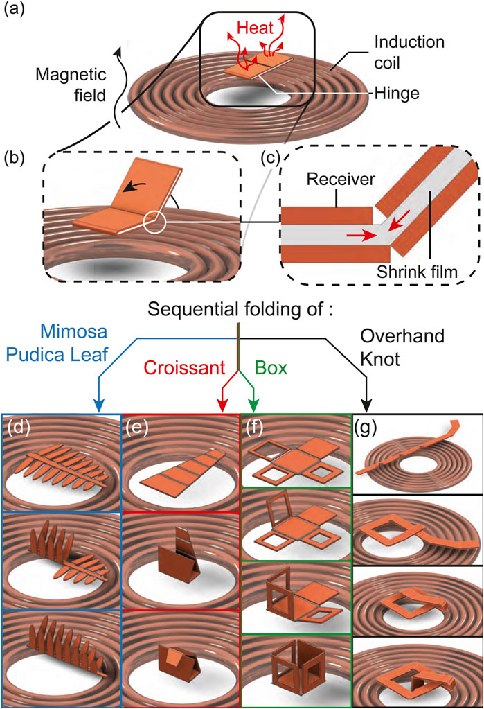
Figure 1. Concept of sequential folding utilizing magnetic induction. Our self-folding structure is placed onto a coil generating an alternating magnetic field which heats up the structure (A) and causes it to self-fold (B) due to the shrinkage of a film within the structure (C). This enabled the sequential folding of a bio-mimetic leaf (D), a croissant (E), a box (F) and an overhand knot (G).
2 Methods
2.1 Self-folding overhand knot design
Designing string-based structures, such as knots, presents challenges for self-folding techniques such as deformation based on infinite degree of freedom, required folding torque and self-collisions. We propose a methodology to design the knot and position its hinges so that the string can fold with limited degrees of freedom into an overhand knot. Topologically, knots consist of helices with varying pitches, revolutions, and directions, reflecting their chirality.
To obtain an overhand knot from a folding pattern, we split the knot into a helix and a loop (Figure 2A) which are discretized using hinges (Figure 2B). The loop can be envisioned as any
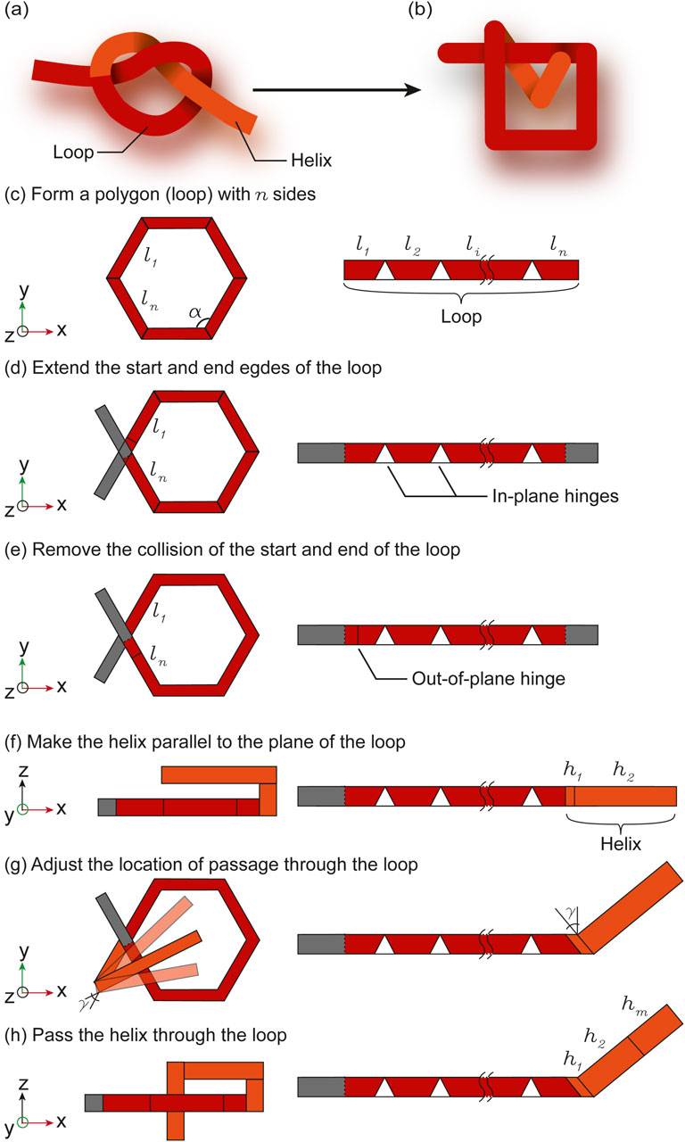
Figure 2. Translation of the overhand knot with continuous deformation (A) to discontinuous deformation (B). The loop is formed from a polygon (C), of which a corner is split in two ends that are extended (D). An out-of-plane hinge is placed to avoid collisions between the two ends of the loop (E). The helix is folded parallel to the plane of the loop by placing two out-of-plane hinges on the helix (F). The location of the passage of the helix through the loop is adjusted by tuning the angle
With the topology and hinge requirements defined, we ensure the overall geometry of the knot prevents the collisions between the segments during folding. The string has a width
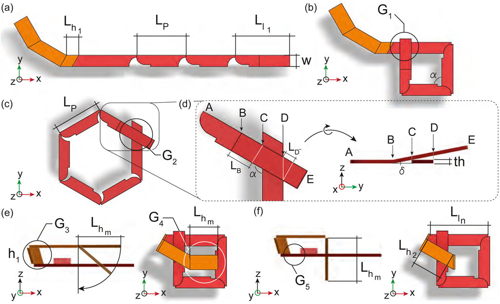
Figure 3. Simulation of the knot folding from the crease pattern proposed by the overhand knot design methodology. The string is initially in its flat state (A), then the loop in red folds (B, C) until the ends of the loop crosses (D), the helix places itself parallel to the loop (E), and passes through the loop (F).
The first geometrical requirement,
2.2 Design of self-folding in-plane hinges
To create the in-plane hinges necessary for the loops shown in Figures 2, 3, placing an out-of-plane hinge on its side (Figure 4A) is possible, although when using magnetic induction heating, maximizing the surface area of induction, that is the surface of the receiver perpendicular to the magnetic field direction, is critical. Therefore, a new hinge design maintaining the surface area of induction, regardless of the folding angle, and limiting the required folding torque to ensure scalability is essential. To address these requirements, we developed a hinge design that remains in-plane while folding (Figure 4C).
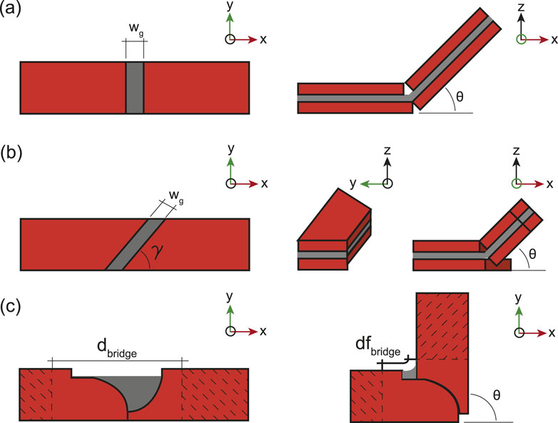
Figure 4. Types of self-folding hinges used in this study. Straight out-of-plane hinge (A), angled out-of-plane hinge (B), and the newly developed in-plane hinge (C).
As illustrated in Figure 4C, the in-plane hinge consists of two round inductor receivers made of copper (in orange) interconnected by a polyvinyl chloride (PVC) shrink film smart material (in grey) which, upon heating above
2.3 Fabrication process and experimental setup
The materials used include a
2.4 Layer configurations
Miniaturizing self-folding hinges for magnetic induction-based folding is challenging, as reducing the structure’s surface area of induction decreases the power induced in the copper receivers. This subsection proposes a receiver layer configuration to enhance the power reception from the induction coil enabling smaller self-foldable structures, and introducing sequential folding by tuning the heat rates between induction receiver.
The common dual-layer structure (Figure 5A) allows heat loss from receivers to the environment and the smart material. A conventional alternative is the tri-layer configuration (Figure 5B), which sandwiches the smart material between passive rigid layers known as structural layer. This setup traps the heat and doubles the receiver surface area of induction, increasing the heat rate. Additionally, the structural layers in the tri-layer configuration act as mechanical limiters to regulate the folding angle. Our approach, the blanket configuration (Figure 5C) interconnects top and bottom receivers and simplifies the fabrication process by manually folding the copper receivers around the smart material, instead of manually positioning the top copper receivers onto the PVC film.
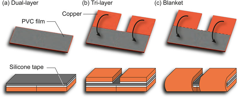
Figure 5. Layer configuration including the dual-layer (A), the tri-layer (B) and the blanket configuration (C).
2.5 Model of the magnetic induction heating
The purpose of the model is to predict the folding sequence by considering factors such as the heat rates of the copper receivers, their design, materials, position on the coil, and magnetic field characteristics.
Induction heating leverages oscillating magnetic fields that induce eddy currents in materials. These induced currents flow along the perimeter of the receiver, generating heat through the Joule heating effect. Furthermore, the electrons moving within the copper receivers are affected by the skin effect, which causes the current to concentrate near the edge of the receivers. This phenomenon ensures that higher frequencies result in shallower skin depths (the depth of the current concentration), thereby localizing the heating effect to the perimeter of the receivers.
We divided the model into three components: magnetic, thermal, and mechanical, depicted in Figure 6A in blue, red, and green, respectively. The electro-magnetic analysis calculates the power induced in the receiver
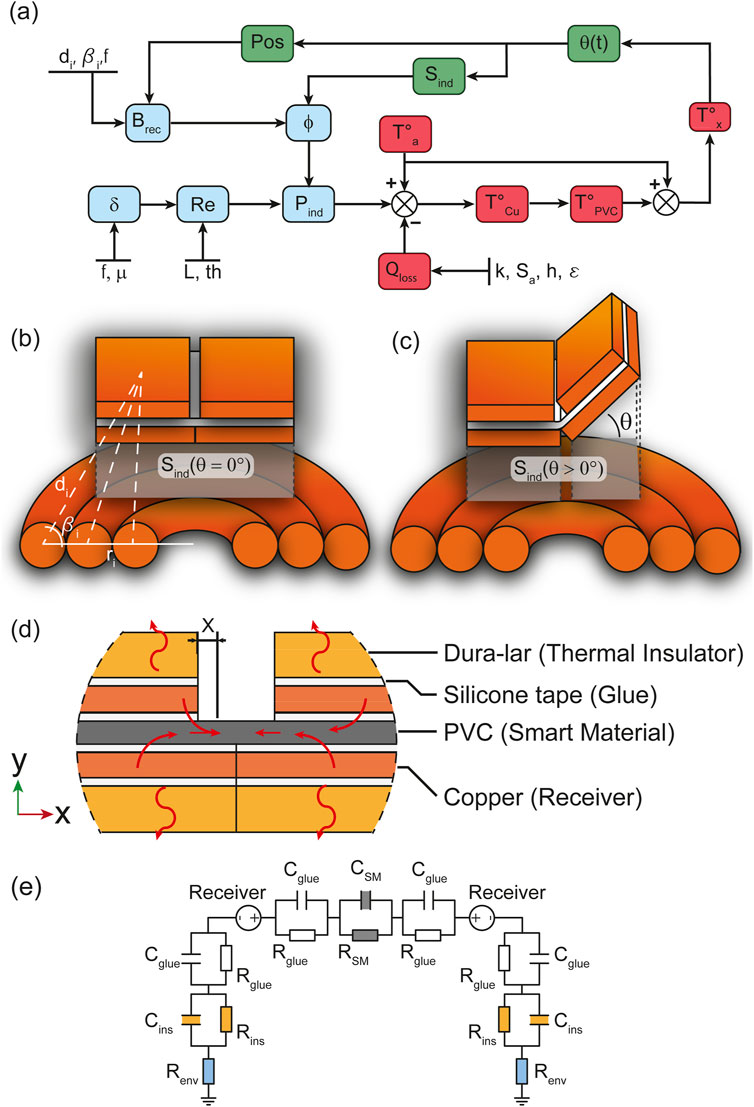
Figure 6. Overview of the model (A) showing how electro-magnetic, thermal and mechanics interact to describe the self-folding hinges. The coupling variation between receiver and coil when the hinge’s receiver is flat (B) and folding (C). The sideview of the multi-layer self-folding structure showcasing the structure layout and thermal exchange within the it (D). The electric equivalent of the heat transfer within the multi-layer structure illustrating heat storage and conductivity (E).
2.5.1 Power induced and receiver design
The primary objective of the magnetic section is to determine the electrical power delivered to the receiver. Initially, the magnetic field received
where the index
From the calculation of the magnetic field received (Equation 1), the power induced within the induction receivers can be calculated as shown in Equation 2:
where
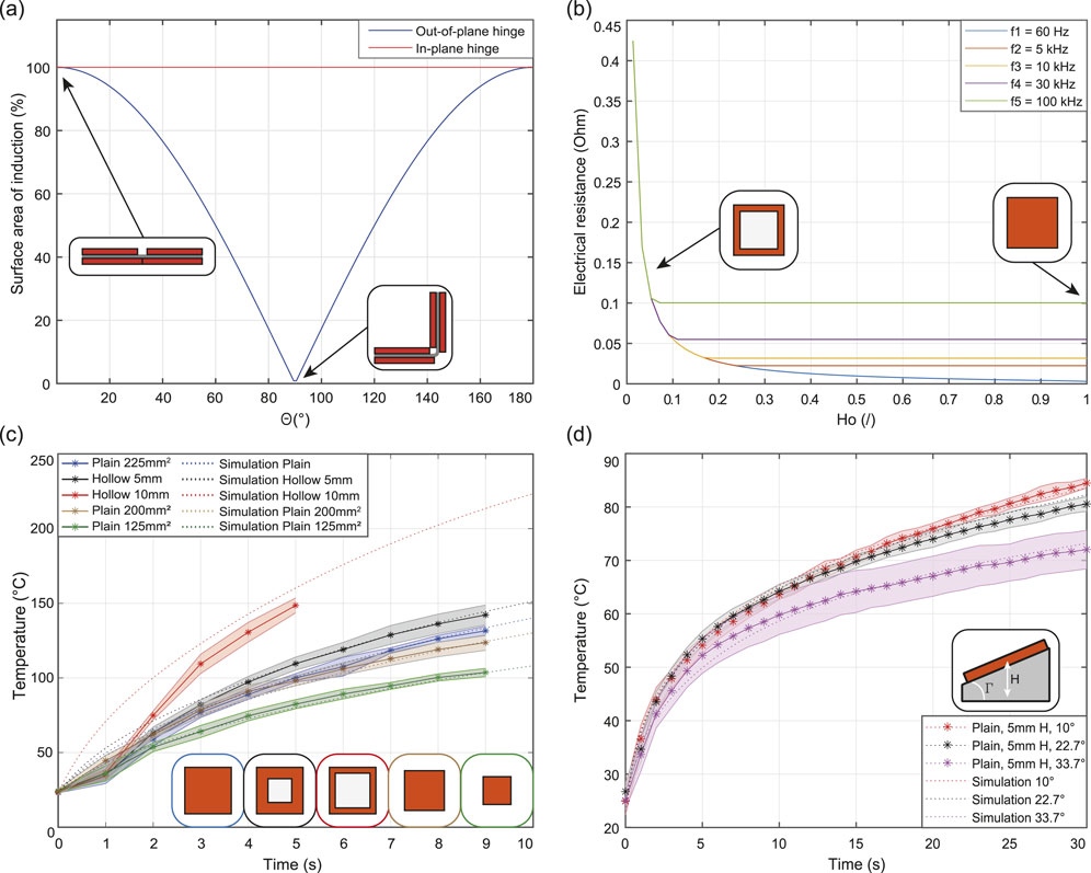
Figure 7. Results of the modelling and experimental characterisation. The surface area of induction against the folding angle for the in-plane and out-of-plane hinges (A). Variation of electrical resistance as a function of the hollowness ratio of a
Another factor is the electrical resistance
with
Consequently, as electrons generate heat via the Joule heating effect, the sides of the receiver heat more than its center, causing the central part to function as a heat sink. This suggests that removing the central material can increase the heat rate of receivers and the folding rate. This is validated by the plot in Figure 7B, which shows the change in the resistance of an induction receiver as a function of the hollowness
2.5.2 Heat generation and losses
This section examines the thermal characteristics of the system to determine the start of the self-folding, which occurs when the copper receiver reaches
Figure 6D; Supplementary Figure S1i in the SupplementaryMaterial illustrate the PVC film positioned between layers of silicone tape, copper receivers, and Dura-Lar thermal insulators. The heat generated by the copper receivers is transferred through these layers, characterized by their thermal conductivity
The heat trapped between the receivers can only be conducted towards the hinge, where the PVC film is free to shrink. According to the folding angle prediction model Tolley et al. (2014), the PVC film needs to shrink by 10.3% to achieve complete folding, regardless of the hinge gap,
For simplicity and visibility in infrared, the following characterization was performed on a receiver/adhesive paper bilayer. The heat conduction from the periphery towards the center of the receiver was neglected, as the measured point was at the periphery due to the skin effect. Despite potential inaccuracies in folding sequence predictions, this assumption is relevant since the self-folding hinges are located at the corners of the receivers.
The first thermal simulation demonstrates the design’s impact on the heat rate by varying the hollowness of square copper receivers. Copper receivers with surfaces of 225, 200, and 125 mm2 were tested, along with hollow receivers with
The Simulink thermal model accurately followed the experimental trends with a discrepancy of less than
2.5.3 Self-folding and stalling angle
This section analyzes the impact of copper receiver positioning on heat generation and folding behavior. In the second simulation, a 225 mm2 receiver was inclined at an angle
As the receiver folds towards
3 Results
This section presents the implementation of the design and model conclusions to achieve sequential folding through magnetic induction. The process is demonstrated by self-folding various structures, including a bio-inspired Mimosa pudica leaf, a croissant, a box, and an overhand knot.
3.1 Single hinge self-folding
To assess the heat generation as a function of the layer configuration, six dual-layer, seven tri-layer, and eight blanket configurations, each with
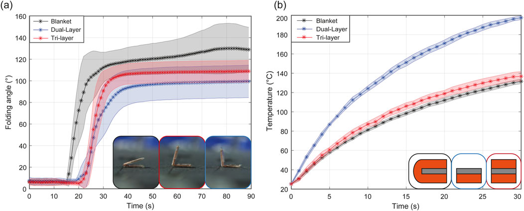
Figure 8. Experimental data of the folding angle of hinges (A) and temperature increase (B) depending on the layer configuration.
3.2 Receiver size for sequential folding
This experiment aims to demonstrate sequential folding by varying the heating rate of receivers of different sizes. Inspired by the mimosa pudica, which sequentially closes its leaves upon physical touch, a bio-mimetic self-folding leaf was designed and fabricated to exhibit a sequential folding response to heat. The leaf measures 40 mm in length and 30 mm in width, with 16 sub-leaves ranging in size from 33.8 mm2 to 12.1 mm2. The sub-leaves are symmetrically arranged along the stem and numbered in pairs from 1 to 8, with each pair having the same surface area of induction to ensure simultaneous folding. The sub-leaves were fabricated using a tri-layer approach, while the stem utilized a blanket configuration to supply heat along its length. The leaf was positioned such that the center of the induction coil was between the third and fourth sub-leaves, providing maximum power to these sub-leaves and decreasing for those farther away (Figure 9A). As shown in Figure 9B and as seen in Supplementary Video S4, sub-leaves pairs 1 to 5 simultaneous folded in 23 s. Depicted in Figures 9C, D, F, sub-leaves 6, 7, and 8 sequentially folded in 32, 39, and 60 s respectively, resulting in the self-folded bio-mimetic Mimosa pudica leaf in Figures 9E, F. Sequential folding using different receiver sizes is therefore validated. This approach to sequential folding may be applied to a wide range of origami patterns by fragmenting the receivers into smaller surfaces, thus reducing the heat rates of individual receivers.
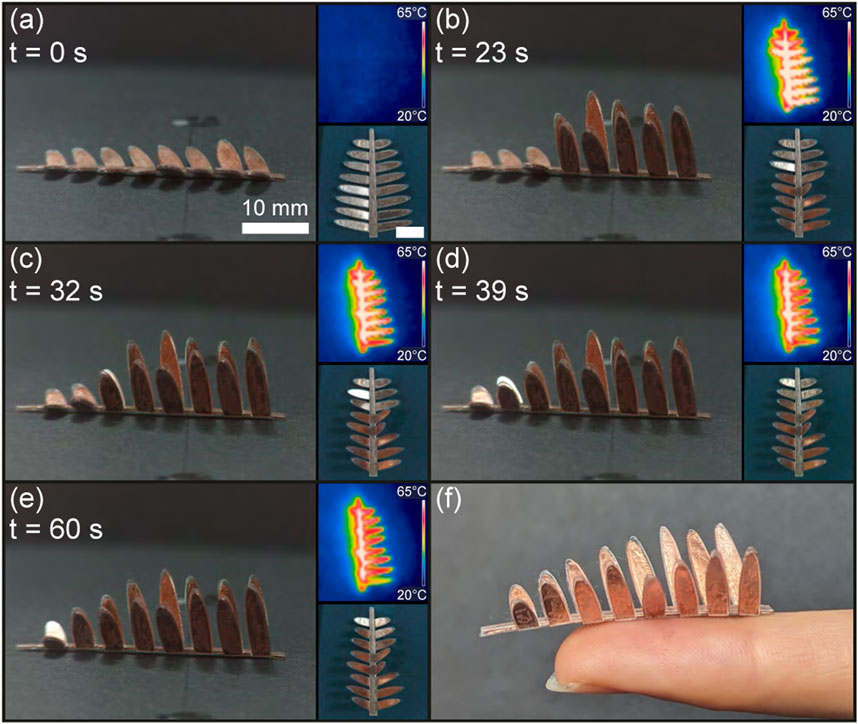
Figure 9. Sequential self-folding of the bio-mimetic Mimosa pudica leaf. The leaf in its flat state (A) self-folds its sub-leaves pair 1 to 5 (B), followed by layer 6 (C), 7 (D), and 8 (E), resulting in the fully self-folded Mimosa pudica leaf (F).
3.3 Receiver size and placement for sequential folding
The objective of this experiment is to demonstrate sequential folding of the croissant structure by positioning receivers of varying sizes at different distances from the induction coil center, thereby creating heat rate disparities due to differences in received power.
The croissant consists of five trapezoidal blanket-type receivers arranged in decreasing size, connected at the small base of the trapezoid from largest to smallest. The receiver areas are 136.5, 98.7, 68.8, 46, and 29.2 mm2. In the experiment, the unfolded croissant was placed so that the center of mass of the second receiver was aligned with the coil’s central axis. The largest receiver was expected to fold first, followed by the smaller receivers in order of their proximity to the coil center.
Figure 10 and Supplementary Video S5 illustrate the folding process, showing the croissant folding sequentially in 70 s into its final rolled shape. In the final stage, the smallest receiver folds around the largest trapezoid base, locking the structure. However, the largest receivers folded simultaneously followed by the predicted order of size of receivers. This is due to insufficient design features, such as holes, to create distinct heat rate variations or magnetic field non-uniformities across the hand-made induction coil, but suggests that the proximity with the center of the coil is the most impacting factor. Additionally, folding in the opposite direction was observed between Figures 10A, B which may be attributed to the thermal dependency of the PVC film’s stiffness and deformation due to the load on the hinges along with the PVC film thermal expansion.
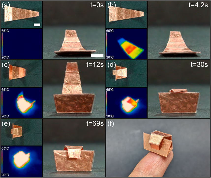
Figure 10. Sequential folding of the croissant by using receivers of different sizes and distances from the center of the coil (A–E), and perspective view of the croissant layer on the tip of an index finger (F). Scale bar is 5 mm.
Additionally, the sub-leaves can be seen unfolding as they heat up below
3.4 Receivers heat capacity for sequential folding
This experiment aims to achieve sequential folding of a box by introducing holes in the receivers to alter their heat capacity.
The cubical box,
As a result, when placed at the coil center, the box self-folded in 70 s following the expected sequence. As shown in Figure 11 and Supplementary Video S6, the
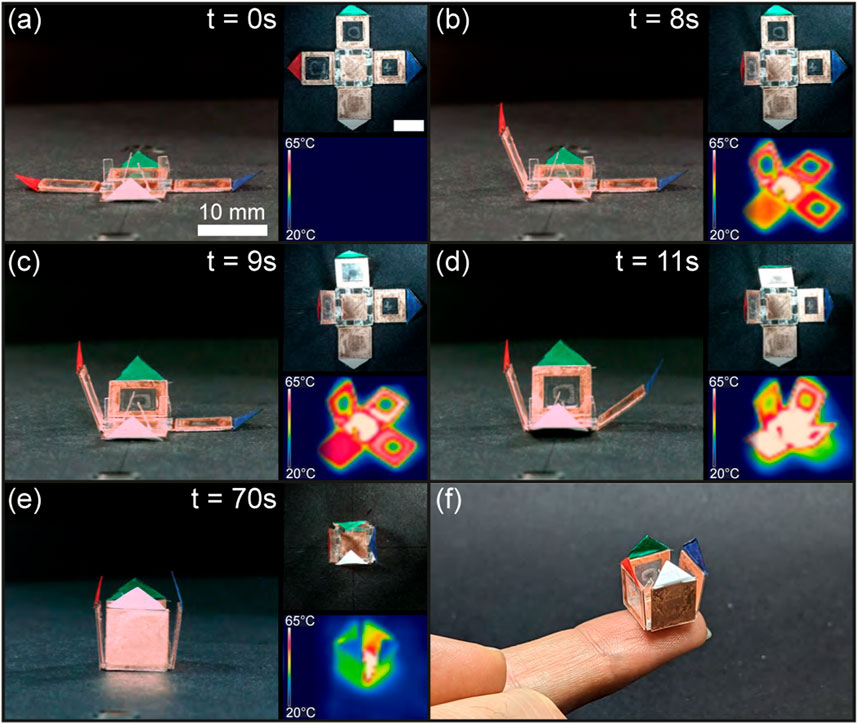
Figure 11. Sequential folding of the box. The structure in its flat state (A) folds first its receiver with an 8 mm wide hole (red) (B), followed by the receiver with a 6 mm wide hole (green) (C), the 4 mm wide hole receiver (blue) (D), and the plain receiver (white) until completion of the folding (E). Pictures from another perspective (F).
Unlike the croissant structure, each copper receiver of the box has a distinct hollowness inducing large heat rate discrepancies, and to achieve a clear folding sequence, the impact of reducing the surface area of induction of the central receiver is demonstrated. This method, which can be used at various scales, allows for any receiver to be made hollow and, if necessary, reinforced with rigid material. In addition, this approach can be applied to various structures, such as a 1D self-folding string or a 2D origami pattern.
3.5 Self-folding of the overhand knot
To fold an overhand knot, the loop must form first, followed by the helix passing through the loop. This can be achieved by altering the design and size of the copper receivers to self-fold the knot.
The methodology developed in Section 2.1 proposes forming a polygon loop with a strip whose ends do not cross. The loop forms a square with an internal length of 16 mm, covering 676 mm2 around the center of the induction coil. Instead of adding a hinge to the first segment of the loop as mentionned in Section 2.1, it was manually bent upward before the experiment to prevent the loop ends from colliding during self-folding. Hollow receivers were used for the loop, placed centrally in the workspace to increase their heat rate. In addition, the length of the knot and in-plane motion introduced frictional torques between the workspace and the knot, causing the knot to displace when folding and the in-plane hinges to stop folding. To limit the influence of friction, two layers of PVC film were introduced to increase the folding torque, and the knot was anchored by gluing receiver
Figure 12, as well as the Supplementary Video S7, demonstrate the self-folding of the overhand knot and its infrared thermal readings. As shown in Figure 12B, the loop heats and folds first in
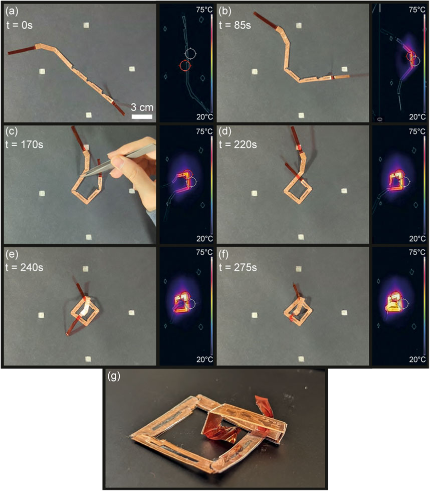
Figure 12. Sequential self-folding of the overhand knot. The knot is first in a flat state (A), folds its loop (B, C) before folding the helix parallel to the plane of the loop (D, E), and passes through the loop (F) giving the perspective view in (G).
The overhand knot self-folding was conducted in four trials, each requiring human intervention to fully fold the loop. Single hinge tests in the workspace’s center showed high success rates for in-plane hinges (Supplementary Figure S2). This implies that the out-of-plane torque induced by the length of the knot causes the in-plane hinge receivers to unhinge, intertwine and lock. In addition, improper insulation placement can cause the folded in-plane hinge receivers to contact, increasing the surface area of induction, sharply raising the temperature, and potentially melting the PVC film. Therefore, further design iterations and trials are needed to improve the in-plane hinge’s resilience to out-of-plane torques and safety. Additionally, to prevent the friction from offsetting the knot placement, the knot was anchored with glue, which restricted the PVC film from receiver
4 Discussion
4.1 Comparison with the literature
Here our system working at
4.2 Convection coefficient in self-folding systems
The convection coefficient
4.3 Blanket configuration limitation
Fabricating self-folding structures presents challenges, particularly in the precise positioning and alignment of top and bottom receivers and thermal insulators, which leads to incorrect folding angles and sequences. While the blanket configuration helps align the receivers, its applicability is limited to certain patterns. For instance, in the crease pattern of the box in Figure 13A, the central receiver cannot use the blanket method and must be manually positioned. However, modifying the crease pattern in Figure 13B allows all hinges to use the blanket configuration. Although both patterns result in the same box structure, the axis of rotation for the amended receiver 3 depends on its attachment to receiver 4 (Figure 13C). Assuming that the central receiver aligns with the coil center, reduced heat generation from increased distance and double rotation between receivers
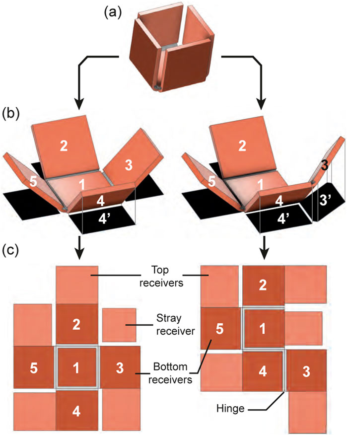
Figure 13. Limitation of the blanket configuration. The target box structure (A) has different possible folding pattern (B) (with numbered bottom panels in dark orange and top panels in light orange) which gives a folding configuration (C) with projected surface area of induction in black.
4.4 Miniaturization of self-folding structures
Adjusting the design of the receivers and their layer configuration increases heat rates, facilitating the scaling down of structures. For miniaturization, the PVC film can be replaced with another thermo-responsive shrink film with a lower glass transition temperature, such as polyurethane film. Alternatively, the power of the induction coil can be increased, or the environmental temperature elevated. Custom-made bio-compatible polyurethane filaments, shrinking at
4.5 Workspace and up-scaling the size of self-folding structures
The self-folding region is smaller than the induction coil surface because the magnetic field amplitude decreases quadratically with the distance from the coil center. However, this region size can be adjusted by increasing the coil power, frequency, and geometry, or by changing the receivers’ size, design, layer configuration, magnetic materials, and thermal insulation. Increasing the size of the coil to increase the self-folding region is also a viable approach, although the geometry affects the uniformity of the magnetic field along with the resonance frequency, which requires a balance between the inductance
4.6 Induction coil and safely self-folding region
As mentioned in Section 2.5, overheating of the PVC film generates highly toxic, corrosive white fumes of hydrogen chloride. To prevent the production of these fumes, it is crucial to consider overheating regions in addition to the self-folding region, ensuring that any copper receiver remains below the PVC film’s melting temperature of
5 Conclusion
In conclusion, this study presents a novel approach to sequentially self-fold an origami into a target structure through magnetic induction heating. The methodology involving modifications to the receivers, including design, size, configuration of receivers, as well as their placement on the induction coil, was successful for the achievement of sequential folding with the main factor being the distance coil/receiver. This mainly manifested by tuning the heat rate of each receiver highlighting the existence of self-folding regions to properly self-fold structures. The fabrication process of magnetic induction-based self-folding structures was established, and the magneto-thermal model was developed to predict folding sequences based on design parameters of the self-folding structure and magnetic field characteristics. The effectiveness of this approach was validated through thermal and folding speed tests on various structures, including a croissant, a box, and a biomimetic Mimosa pudica leaf. Additionally, the methodology was successfully applied to the self-folding of an overhand knot with minimal assistance at this stage, illustrating its potential for complex structures such as self-locking structures including knots.
This research introduces design recommendations for induction heating-based sequential self-folding, which expand the range of foldable structures as small as 5 mm. In the future, further reducing the working frequency to increase the depth penetration and biocompatibility of the system, while maintaining sufficient heat generation for self-folding, is necessary to introduce induction heating based origami for in vivo applications. This includes self-stitching sutures to reduce surgical invasiveness and post-surgery infections, contingent upon the use of biocompatible materials with lower activation temperatures such as polyurethanes. Furthermore, the design parameters for creating folding sequences can be utilized to prevent the unfolding of origami structures or for applications requiring self-locking to secure cargos such as drug delivery or biopsy.
Data availability statement
The raw data supporting the conclusions of this article will be made available by the authors, without undue reservation.
Author contributions
QL: Conceptualization, Investigation, Methodology, Validation, Visualization, Writing–original draft. SM: Conceptualization, Methodology, Project administration, Writing–review and editing.
Funding
The authors declare that financial support was received for the research, authorship, and/or publication of this article. We thank the University of Sheffield Institutional Open Access Fund for funding the publication of this article
Acknowledgments
We thank Xiao Chen for his support on the fabrication of self-folding structures, Kaan Esendag for developing the induction system. We also thank Umur Harman, Zihan Zhao, Junyi Han and Ahmed Hafez for their support on reviewing the manuscript. We inform the reader that we used ChatGPT version 4o to improve the english quality and proofread the text.
Conflict of interest
The authors declare that the research was conducted in the absence of any commercial or financial relationships that could be construed as a potential conflict of interest.
Publisher’s note
All claims expressed in this article are solely those of the authors and do not necessarily represent those of their affiliated organizations, or those of the publisher, the editors and the reviewers. Any product that may be evaluated in this article, or claim that may be made by its manufacturer, is not guaranteed or endorsed by the publisher.
Supplementary material
The Supplementary Material for this article can be found online at: https://www.frontiersin.org/articles/10.3389/frobt.2024.1443379/full#supplementary-material
References
Balkcom, D. J., and Mason, M. T. (2004). “Introducing robotic origami folding,” in IEEE International Conference on Robotics and Automation, 2004. Proceedings, New Orleans, LA, April 26–May 1, 2004 (IEEE), 3245–3250.
Boncheva, M., Andreev, S. A., Mahadevan, L., Winkleman, A., Reichman, D. R., Prentiss, M. G., et al. (2005). Magnetic self-assembly of three-dimensional surfaces from planar sheets. Proc. Natl. Acad. Sci. 102, 3924–3929. doi:10.1073/pnas.0500807102
Boyvat, M., Koh, J.-S., and Wood, R. J. (2017). Addressable wireless actuation for multijoint folding robots and devices. Sci. Robotics 2, eaan1544. doi:10.1126/scirobotics.aan1544
Davis, D., Mailen, R., Genzer, J., and Dickey, M. D. (2015). Self-folding of polymer sheets using microwaves and graphene ink. Rsc Adv. 5, 89254–89261. doi:10.1039/c5ra16431a
Deatsch, A. E., and Evans, B. A. (2014). Heating efficiency in magnetic nanoparticle hyperthermia. J. Magnetism magnetic Mater. 354, 163–172. doi:10.1016/j.jmmm.2013.11.006
Denmark, D., Bradley, J., Mukherjee, D., Alonso, J., Shakespeare, S., Bernal, N., et al. (2016). Remote triggering of thermoresponsive pnipam by iron oxide nanoparticles. RSC Adv. 6, 5641–5652. doi:10.1039/c5ra21617f
Downs, F. G., Lunn, D. J., Booth, M. J., Sauer, J. B., Ramsay, W. J., Klemperer, R. G., et al. (2020). Multi-responsive hydrogel structures from patterned droplet networks. Nat. Chem. 12, 363–371. doi:10.1038/s41557-020-0444-1
du Plessis d’Argentré, A., Perry, S., Iwata, Y., Iwasaki, H., Iwase, E., Fabozzo, A., et al. (2018). “Programmable medicine: autonomous, ingestible, deployable hydrogel patch and plug for stomach ulcer therapy,” in 2018 IEEE International Conference on Robotics and Automation (ICRA), Brisbane, QLD, May 21–25, 2018 (IEEE), 1511–1518.
Felton, S. M., Tolley, M. T., Shin, B., Onal, C. D., Demaine, E. D., Rus, D., et al. (2013). Self-folding with shape memory composites. Soft Matter 9, 7688–7694. doi:10.1039/c3sm51003d
Firouzeh, A., and Paik, J. (2015). Robogami: a fully integrated low-profile robotic origami. J. Mech. Robotics 7, 021009. doi:10.1115/1.4029491
Ghosh, S., Yang, C., Cai, T., Hu, Z., and Neogi, A. (2009). Oscillating magnetic field-actuated microvalves for micro-and nanofluidics. J. Phys. D Appl. Phys. 42, 135501. doi:10.1088/0022-3727/42/13/135501
Guan, J., He, H., Hansford, D. J., and Lee, L. J. (2005). Self-folding of three-dimensional hydrogel microstructures. J. Phys. Chem. B 109, 23134–23137. doi:10.1021/jp054341g
Huang, H.-W., Tibbitt, M. W., Huang, T.-Y., and Nelson, B. J. (2019). Matryoshka-inspired micro-origami capsules to enhance loading, encapsulation, and transport of drugs. Soft Robot. 6, 150–159. doi:10.1089/soro.2018.0028
Ishikawa, N., Watanabe, G., Hirano, Y., Inaki, N., Kawachi, K., and Oda, M. (2007). Origami using da vinci surgical system. Surg. Endosc. 21, 1252–1253. doi:10.1007/s00464-007-9416-4
Iwase, E., and Shimoyama, I. (2006). A design method for out-of-plane structures by multi-step magnetic self-assembly. Sensors Actuators A Phys. 127, 310–315. doi:10.1016/j.sna.2006.01.025
Iwata, Y., Miyashita, S., and Iwase, E. (2017). Self-rolling up micro 3d structures using temperature-responsive hydrogel sheet. J. Micromechanics Microengineering 27, 124003. doi:10.1088/1361-6439/aa94b4
Jaafar, M. F. (2013). “Magnetic hysteresis modeling and numerical simulation for ferromagnetic materials,” in 2013 International Conference on Control, Decision and Information Technologies (CoDIT), Hammamet, Tunisia, May 6–8, 2013 (IEEE), 516–523.
Jing, X., Mi, H.-Y., Huang, H.-X., and Turng, L.-S. (2016). Shape memory thermoplastic polyurethane (TPU)/poly(ε-caprolactone) (PCL) blends as self-knotting sutures. J. Mech. Behav. Biomed. Mater. 64, 94–103. doi:10.1016/j.jmbbm.2016.07.023
Keneth, E. S., Lieberman, R., Pahima, A., Varma, V. B., Sharma, V., Yuan, C., et al. (2023). Untethered magneto-thermal flexible actuators for soft robotics. Sensors Actuators A Phys. 363, 114683. doi:10.1016/j.sna.2023.114683
Kening, Z., Nii, H., Fernando, O. N. N., and Cheok, A. D. (2011). “Selective inductive powering system for paper computing,” in Proceedings of the 8th International Conference on Advances in Computer Entertainment Technology, Lisbon, Portugal, November 8–11, 2011, 1–7.
Kim, C., Chien, A., Tippur, M., and Sung, C. (2021). “Fabrication and characterization of i-cord knitted sma actuators,” in 2021 IEEE 4th International Conference on Soft Robotics (RoboSoft), New Haven, CT, April 12–16, 2021 (IEEE), 379–386.
Kobayashi, K., Oh, S. H., Yoon, C., and Gracias, D. H. (2018). Multitemperature responsive self-folding soft biomimetic structures. Macromol. rapid Commun. 39, 1700692. doi:10.1002/marc.201700692
Kuang, X., Roach, D. J., Wu, J., Hamel, C. M., Ding, Z., Wang, T., et al. (2019). Advances in 4d printing: materials and applications. Adv. Funct. Mater. 29, 1805290. doi:10.1002/adfm.201805290
Kuribayashi, K., Tsuchiya, K., You, Z., Tomus, D., Umemoto, M., Ito, T., et al. (2006). Self-deployable origami stent grafts as a biomedical application of ni-rich tini shape memory alloy foil. Mater. Sci. Eng. A 419, 131–137. doi:10.1016/j.msea.2005.12.016
Lahondes, Q., and Miyashita, S. (2022). “Temperature driven soft reversible self-folding origami string,” in 2022 IEEE 5th International Conference on Soft Robotics (RoboSoft), Edinburgh, United Kingdom, April 4–8, 2022 (IEEE), 589–594.
Lahondes, Q. M. P., Wilmot, A., and Miyashita, S. (2020). Origami-inspired microrobots. Berlin, Heidelberg: Springer Berlin Heidelberg, 1–11. doi:10.1007/978-3-642-41610-1_195-1
Lendlein, A., and Langer, R. (2002). Biodegradable, elastic shape-memory polymers for potential biomedical applications. Science 296, 1673–1676. doi:10.1126/science.1066102
Li, H., Go, G., Ko, S. Y., Park, J.-O., and Park, S. (2016). Magnetic actuated ph-responsive hydrogel-based soft micro-robot for targeted drug delivery. Smart Mater. Struct. 25, 027001. doi:10.1088/0964-1726/25/2/027001
Li, J., and Liu, Z. (2018). Focused-ion-beam-based nano-kirigami: from art to photonics. Nanophotonics 7, 1637–1650. doi:10.1515/nanoph-2018-0117
Li, Y., Qi, Z., Yang, J., Zhou, M., Zhang, X., Ling, W., et al. (2019). Origami ndfeb flexible magnetic membranes with enhanced magnetism and programmable sequences of polarities. Adv. Funct. Mater. 29, 1904977. doi:10.1002/adfm.201904977
Liu, J., Chen, X., Lahondes, Q., Esendag, K., Damian, D., and Miyashita, S. (2022). “Origami robot self-folding by magnetic induction,” in 2022 IEEE/RSJ International Conference on Intelligent Robots and Systems (IROS), Kyoto, Japan, October 23–27, 2022 (IEEE), 2519–2525.
Liu, Y., Shaw, B., Dickey, M. D., and Genzer, J. (2017). Sequential self-folding of polymer sheets. Sci. Adv. 3, e1602417. doi:10.1126/sciadv.1602417
Ma, K. Y., Chirarattananon, P., Fuller, S. B., and Wood, R. J. (2013). Controlled flight of a biologically inspired, insect-scale robot. Science 340, 603–607. doi:10.1126/science.1231806
Miyashita, S., Guitron, S., Li, S., and Rus, D. (2017). Robotic metamorphosis by origami exoskeletons. Sci. Robotics 2, eaao4369. doi:10.1126/scirobotics.aao4369
Miyashita, S., Guitron, S., Yoshida, K., Li, S., Damian, D. D., and Rus, D. (2016). “Ingestible, controllable, and degradable origami robot for patching stomach wounds,” in 2016 IEEE international conference on robotics and automation (ICRA), Stockholm, Sweden, May 16–21, 2016 (IEEE), 909–916.
Mohr, R., Kratz, K., Weigel, T., Lucka-Gabor, M., Moneke, M., and Lendlein, A. (2006). Initiation of shape-memory effect by inductive heating of magnetic nanoparticles in thermoplastic polymers. Proc. Natl. Acad. Sci. 103, 3540–3545. doi:10.1073/pnas.0600079103
Na, J.-H., Evans, A. A., Bae, J., Chiappelli, M. C., Santangelo, C. D., Lang, R. J., et al. (2015). Programming reversibly self-folding origami with micropatterned photo-crosslinkable polymer trilayers. Adv. Mater. 27, 79–85. doi:10.1002/adma.201403510
Namiki, A., and Yokosawa, S. (2015). “Robotic origami folding with dynamic motion primitives,” in 2015 IEEE/RSJ International Conference on Intelligent Robots and Systems (IROS), Hamburg, Germany, September 28–October 02, 2015 (IEEE), 5623–5628.
Non-Ionizing Radiation Protection (2020). Guidelines for limiting exposure to electromagnetic fields (100 khz to 300 ghz). Health Phys. 118, 483–524. doi:10.1097/HP.0000000000001210
Onal, C. D., Wood, R. J., and Rus, D. (2012). An origami-inspired approach to worm robots. IEEE/ASME Trans. Mechatronics 18, 430–438. doi:10.1109/tmech.2012.2210239
Razmjou, A., Barati, M. R., Simon, G. P., Suzuki, K., and Wang, H. (2013). Fast deswelling of nanocomposite polymer hydrogels via magnetic field-induced heating for emerging fo desalination. Environ. Sci. & Technol. 47, 6297–6305. doi:10.1021/es4005152
Razzaq, M. Y., Anhalt, M., Frormann, L., and Weidenfeller, B. (2007). Thermal, electrical and magnetic studies of magnetite filled polyurethane shape memory polymers. Mater. Sci. Eng. A 444, 227–235. doi:10.1016/j.msea.2006.08.083
Tang, J., and Sun, B. (2022). Reprogrammable shape transformation of magnetic soft robots enabled by magnetothermal effect. Appl. Phys. Lett. 120. doi:10.1063/5.0093096
Thérien-Aubin, H., Wu, Z. L., Nie, Z., and Kumacheva, E. (2013). Multiple shape transformations of composite hydrogel sheets. J. Am. Chem. Soc. 135, 4834–4839. doi:10.1021/ja400518c
Tolley, M. T., Felton, S. M., Miyashita, S., Aukes, D., Rus, D., and Wood, R. J. (2014). Self-folding origami: shape memory composites activated by uniform heating. Smart Mater. Struct. 23, 094006. doi:10.1088/0964-1726/23/9/094006
Uchida, T., and Onoe, H. (2019). 4d printing of multi-hydrogels using direct ink writing in a supporting viscous liquid. Micromachines 10, 433. doi:10.3390/mi10070433
Zhakypov, Z., and Paik, J. (2018). Design methodology for constructing multimaterial origami robots and machines. IEEE Trans. Robotics 34, 151–165. doi:10.1109/tro.2017.2775655
Keywords: magnetic induction heating, sequential self-folding, origami structures, thermo-responsive, self-folding knot, bio-mimetics
Citation: Lahondes Q and Miyashita S (2024) Remotely actuated programmable self-folding origami strings using magnetic induction heating. Front. Robot. AI 11:1443379. doi: 10.3389/frobt.2024.1443379
Received: 03 June 2024; Accepted: 15 August 2024;
Published: 30 August 2024.
Edited by:
Cagdas D. Onal, Worcester Polytechnic Institute, United StatesReviewed by:
Ahmet Fatih Tabak, Istanbul Commerce University, TürkiyeOncay Yasa, Hong Kong University of Science and Technology, China
Copyright © 2024 Lahondes and Miyashita. This is an open-access article distributed under the terms of the Creative Commons Attribution License (CC BY). The use, distribution or reproduction in other forums is permitted, provided the original author(s) and the copyright owner(s) are credited and that the original publication in this journal is cited, in accordance with accepted academic practice. No use, distribution or reproduction is permitted which does not comply with these terms.
*Correspondence: Quentin Lahondes, cWxhaG9uZGVzQGdtYWlsLmNvbQ==
†ORCID: Quentin Lahondes, orcid.org/0000-0003-0797-7458; Shuhei Miyashita, orcid.org/0000-0002-9795-9247