 Qiwei Zhang1
 Hongbin Fang
94% of researchers rate our articles as excellent or good
Learn more about the work of our research integrity team to safeguard the quality of each article we publish.
Find out more
ORIGINAL RESEARCH article
Front. Robot. AI, 20 August 2021
Sec. Soft Robotics
Volume 8 - 2021 | https://doi.org/10.3389/frobt.2021.738214
This article is part of the Research TopicOrigami Robots: Design, Materials and ApplicationsView all 4 articles
Earthworm-like robots have received great attention due to their prominent locomotion abilities in various environments. In this research, by exploiting the extraordinary three-dimensional (3D) deformability of the Yoshimura-origami structure, the state of the art of earthworm-like robots is significantly advanced by enhancing the locomotion capability from 2D to 3D. Specifically, by introducing into the virtual creases, kinematics of the non-rigid-foldable Yoshimura-ori structure is systematically analyzed. In addition to exhibiting large axial deformation, the Yoshimura-ori structure could also bend toward different directions, which, therefore, significantly expands the reachable workspace and makes it possible for the robot to perform turning and rising motions. Based on prototypes made of PETE film, mechanical properties of the Yoshimura-ori structure are also evaluated experimentally, which provides useful guidelines for robot design. With the Yoshimura-ori structure as the skeleton of the robot, a hybrid actuation mechanism consisting of SMA springs, pneumatic balloons, and electromagnets is then proposed and embedded into the robot: the SMA springs are used to bend the origami segments for turning and rising motion, the pneumatic balloons are employed for extending and contracting the origami segments, and the electromagnets serve as anchoring devices. Learning from the earthworm’s locomotion mechanism--retrograde peristalsis wave, locomotion gaits are designed for controlling the robot. Experimental tests indicate that the robot could achieve effective rectilinear, turning, and rising locomotion, thus demonstrating the unique 3D locomotion capability.
In recent years, earthworm-like locomotion robots have received great attention due to their excellent mobility in narrow space and unstructured environments, enabling many potential applications such as pipe cleaning (Tanise et al., 2017; Fang et al., 2014; Adams et al., 2018), gastrointestinal examination (Wang et al., 2008; Rodríguez et al., 2006), and battlefield surveillance (Fields et al., 2009). The superior locomotive ability of the earthworm-like robots mainly originates from the specially designed robot structure and the elaborated control strategies, where the former is inspired by the earthworm’s unique morphology characteristics, and the latter is a representation of the earthworm’s fundamental locomotion mechanism. Specifically, in terms of the earthworm’s morphology merits, the following three aspects are mainly emphasized: 1) the earthworm’s body consists of a large number of independent working segments separated by septa (Edwards and Bohlen, 1996); 2) each segment possesses circular and longitudinal muscles that work antagonistically to each other (Alexander, 2013), giving rise to interrelated radial and axial deformations of the segment; 3) the bulk of segments have bristle-like setae that can help to anchor parts of the body to the working media during movement (Edwards and Bohlen, 1996). As a consequence, most earthworm-like locomotion robots are designed to be metameric (Fang et al., 2014; Omori et al., 2009; Omori et al., 2008; Isaka et al., 2019; Song et al., 2016), with each robot segment being equipped with antagonistic actuators (Fang et al., 2014; Omori et al., 2009; Omori et al., 2008; Isaka et al., 2019; Song et al., 2016) and anchoring mechanisms (Ge et al., 2017; Daltorio et al., 2013; Tanaka et al., 2012; Horchler et al., 2015). In terms of the locomotion mechanism, by coordinating the deformations of the earthworm’s body segments, a peristalsis wave can be generated, which propagates along the earthworm’s body in the opposite direction to its movement (Quillin, 1999). It has been demonstrated that by alternating the characteristics of the wave, the earthworm could adjust its locomotion mode to adapt to different surroundings (Omori et al., 2009; Ge et al., 2017). Accordingly, learning from the earthworm’s retrograde peristalsis wave, different types of robotic control have been proposed for achieving rectilinear/planar locomotion; the control strategies can be either discrete (e.g., gait tables (Fang et al., 2015a)) or continuous (e.g., phase coordination (Fang et al., 2015b) and wave controller (Boxerbaum et al., 2012)), and their effectiveness have been experimentally verified.
Based on the compliance of the robot’s constituent materials (Trivedi et al., 2008; Majidi, 2014), the existing robot prototypes can be classified into two categories: rigid earthworm-like robots and soft earthworm-like robots. For the former, the robot body is always composed of rigid parts, such as acrylic plates, rigid resin skeletons, and spring-steel belts, etc. (Fang et al., 2014; Zarrouk and Shoham, 2012). In general, a rigid robot segment can be manufactured and assembled relatively easily; it could adapt to various types of actuators (e.g., shape memory alloys (SMA) (Kim et al., 2006) and servomotors (Fang et al., 2014; Kim et al., 2006)), while its deformability is often limited. For the latter, the robot body is always made up of continuously deformable elements (e.g. coupled cables (Daltorio et al., 2013; Kandhari et al., 2018)) or soft/extensible materials (e.g. rubber and silicone (Harigaya et al., 2013; Calderón et al., 2019)). To achieve effective worm-like locomotion, pneumatic actuators (Deng et al., 2020; Tang et al., 2020) and active materials driven by external physical fields (Hu et al., 2018) have been extensively employed, in part because they are very compatible with the soft robot body. The advantage of soft robots is that they can exhibit high continuous deformations and locomotion agility. However, precise control of the soft body is still a big challenge, since the constitutive relations of the soft material and soft actuators have not been well understood. Apart from the inherent pros and cons of the rigid and soft earthworm-like robots, they all meet the challenges in terms of weight and size, which calls for further innovation in robot design.
Despite the abovementioned progresses in understanding and mimicking the earthworm’s morphological characteristics, another important concern of earthworm-like robots is the diversity of locomotion modes. As the first step, rectilinear locomotion has attracted the majority of attention. For example, based on servomotor (Fang et al., 2015a), SMA (Kim et al., 2006), or cable actuators (Boxerbaum et al., 2012) and by prescribing the gait based on earthworms’ peristalsis waves, rectilinear earthworm-like robotic locomotion has been realized in both pipe and open environment. However, rectilinear robotic locomotion, generally, is not sufficient in applications. Note that in nature, earthworms can also perform planar and spatial locomotion. By shortening the longitudinal muscles at one side and stretching the longitudinal muscles at the other side, the earthworm could bend its body and make a turn or make a rise. Inspired by such biology observation and by integrating more independent actuators into the robot design, the locomotion mode has been significantly enriched. For example, with three independent servomotor arms in each segment, Omori et al. developed a four-segment earthworm-like robot that is able to turn on a plane surface and move upward/downward in a vertical pipe (Omori et al., 2009). Similarly, via embedding more actuators into the robot, planar locomotion has also been verified to be feasible in the CMMWorm-S robot (Kandhari et al., 2018), the metameric robot (Zhan et al., 2019), and the Meshworm (Seok et al., 2013). In these successful prototypes, antagonistic axial and radial deformations of the robot segment/part play an important role in achieving locomotion. Segments/parts without such antagonistic deformability can also be utilized for robot design, providing that additional bristle structures (e.g. microspine and clamping devices (Fang D. et al., 2018; Yang et al., 2019)) are embedded to acquire anchoring effect.
Further advancing the locomotion capability of the earthworm-like robot from 2-dimensional (2D) to 3-dimensional (3D) is a nice expectation. However, the development remains stagnant; effective designs and prototypes of earthworm-like spatial locomotion robots have not been reported. One of the reasons lies in that there is a lack of structure that has the advantages of strong 3D deformability, lightweight, and good adaptation to actuators. Origami, originally a recreational art, is a promising platform to tackle the above bottleneck problem due to its limitless design space, extraordinary deformability, and unique reconfigurability. The essence of origami is to construct complex 3D shapes via folding 2D flat sheets following elaborate crease patterns. Even with rigid-folding assumption, the obtained 3D origami structure could exhibit significant deformations by rotating the rigid facets with respect to the creases, which is entirely different from the conventional mechanisms that rely on rigid linkages and movable joints to deform. Moreover, based on folding techniques, thin and weak materials, such as paper and plastic films, become candidates for robot fabrication, making the obtained origami robots extremely light in weight. Particularly, with the introduction of folds, the origami robots would still have sufficient strength and stiffness. In addition, originated from the nonlinear folding kinematics, certain origami structures are well-known for their unorthodox mechanical properties (Li et al., 2019), including negative Poisson’s ratio (Yasuda and Yang, 2015), stiffness re-programmability (Silverberg et al., 2014), structural multistability (Fang et al., 2017a; Li and Wang, 2015, Zhang et al., 2020, Wu et al., 2020), and self-locking (Fang H. et al., 2018), etc.; they provide brand new possibilities for developing robots with novel or enhanced functionalities. With origami techniques, rather than 3D modeling and shaping, design and fabrication of 3D structures can be finished in the 2D realm. The existing 2D design tools and a wide range of commercial 2D fabrication techniques (lithography, laser machining, and basic chemical etching, etc.) could significantly reduce the cost and shorten the production cycle, and meanwhile, remain high machining precision (Onal et al., 2015; Deng and Chen, 2015, Fang et al., 2017b). Such merits also bring exciting opportunities to robot design and fabrication. Considering the similarities in deformation between the earthworm’s body segment and certain origami structures, serval origami-based earthworm-like robots have been proposed to overcome the drawbacks of conventional designs. For example, Fang et al. designed an earthworm-like robot based on the origami ball structure (Fang et al., 2017a). With a positive Poisson’s ratio, the origami ball could exhibit antagonistically-coupled axial and radial deformations, which well mimic the earthworms’ morphology characteristics. Bhovad et al. (Bhovad et al., 2019) and Pagano et al. (Pagano et al., 2017) employed the Kresling origami structure and setae-like feet to achieve peristaltic locomotion, in which the inherent structural bistability has been exploited for fast actuation and easy control.
Note that for these two origami robot prototypes, 1D rectilinear locomotion is the main purpose to achieve. By incorporating two Kresling origami structures in the robot, 2D planar locomotion is also possible (Pagano et al., 2017). Endowing the origami-based earthworm-like robot with expecting 3D spatial locomotion capability is an important direction to explore, while related efforts have not been made. In this research, to advance the state of the art, a new type of Yoshimura-ori-based earthworm-like robot with unique 3D spatial locomotion capability is developed. This is because the Yoshimura-ori structure possesses excellent axial and bending deformability, which can be exploited to break through the current limitations in achieving turning and rising motions in earthworm-like robots. First, to evaluate the deformability of a single robot segment and to predict the reachable workspace, geometry and kinematics of the Yoshimura-ori structure are systematically examined. Mechanical properties of the Yoshimura-ori structure are also evaluated experimentally, which offers useful guidelines for designing actuation. Using the Yoshimura-ori structure as the skeleton, the SMA spring and pneumatic balloon as the hybrid actuation, and the electromagnet as the anchoring device, an earthworm-like robot is designed and prototyped. Based upon the adopted hybrid actuation and anchoring mechanisms and by mimicking the earthworm’s retrograde peristalsis wave, a gait control strategy is also proposed for locomotion control. Experimental tests indicate that the robot could perform effective rectilinear, turning, and rising locomotion, thus successfully expanding the locomotion ability from 2D to 3D.
Figure 1A display the flat crease pattern of the Yoshimura-ori, which can be uniquely defined by four parameters, n, m, L, and β, denoting the number of the basal rectangles, the number of layers, the length of each basal rectangle, and the angle between the diagonal and the length side, respectively. The solid and dashed lines denote the “mountain” and “valley” crease of the pattern. For a single layer, by overlapping points
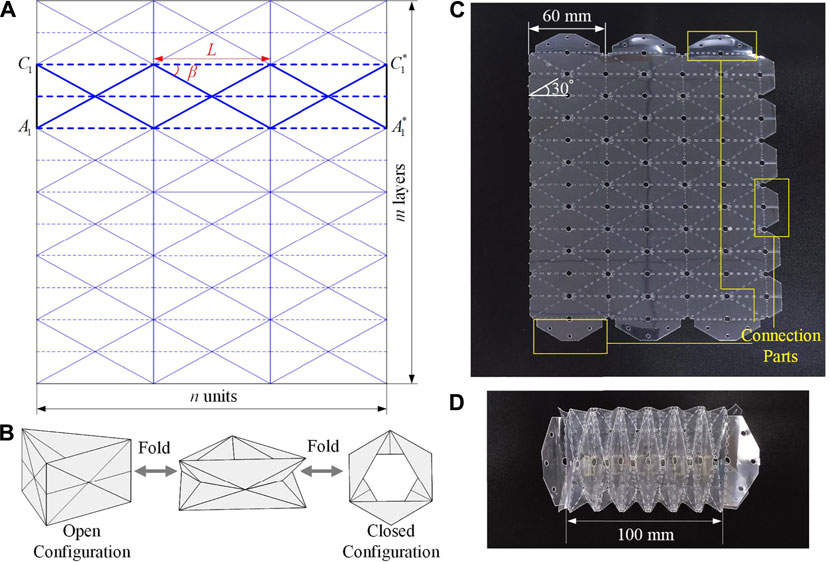
FIGURE 1. Design and prototype of the Yoshimura-ori structure. (A) 2D crease pattern of the
Diverse polyester materials can be used for making origami structures, such as polyether ether ketone (PEEK), polytetrafluoroethylene (PTFK), polyethylene terephthalate (PETE), and polyimide. Among them, PETE film is selected because it can be easily cut, folded, and has a relatively higher softening temperature around
In this section, the folding kinematics of the Yoshimura-ori structure is studied in detail, with major focuses on axial and bending deformability. Assuming that the deformation of each layer is identical, a single-layer Yoshimura-ori structure is taken out for study (Figure 2A). After understanding the folding behavior of a single-layer structure, the reachable workspace of a multi-layer structure is examined, which is an important index for robot design. Note that Yoshimura-ori structure has also been exploited for pneumatic actuation (Paez et al., 2016), energy absorption (Yang et al., 2016), and Barrel Vault (Cai et al., 2015), however, a theoretical framework of folding kinematics has not been developed.
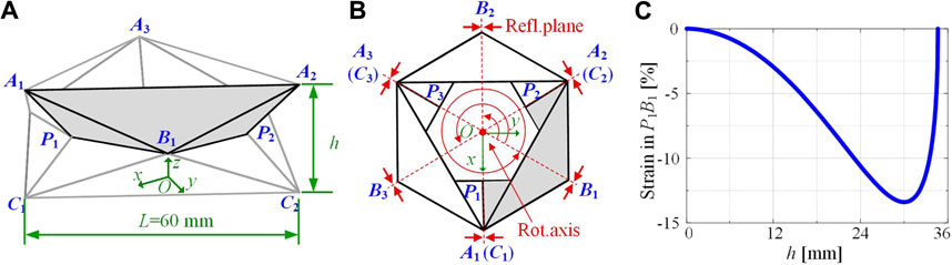
FIGURE 2. A single-layer Yoshimura-ori structure and the theoretical strain change of the crease
We start with analyzing the degree of freedom (DOF) of a single-layer Yoshimura-ori structure. With rigid-folding assumption, the whole structure can be equivalent to a space truss frame. Hence, the DOF of a single-layer Yoshimura-ori structure can be determined by (Saito et al., 2015):
where
To understand the folding kinematics of the Yoshimura-ori structure, a cartesian coordinate system O-xyz is set, with the origin locating at the centroid of the equilateral triangle
As mentioned early, folding of the Yoshimura-ori structure calls for elastic deformations of certain facets or creases. To understand the folding behavior, the lengths of the crease
Based on this, the distance between
While the strain could effectively illustrate the non-rigid-folding of the structure, shortening of the free length
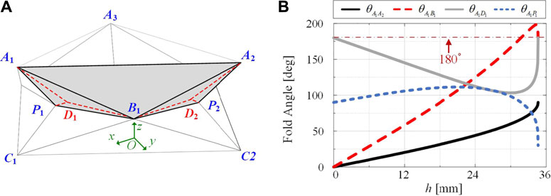
FIGURE 3. Kinematics of a single-layer Yoshimura-ori structure with virtual creases. (A) Introduction of virtual creases to account for facet bending. With virtual creases, panels
When the Yoshimura-ori structure is axially contracted or extended, the position of vertex
Equation 5a indicates that the crease lengths corresponding to
Combining Equations 4, 5, the coordinates of all vertices can be determined at each step of folding via numerical methods. Further, the dihedral angles between adjacent facets can be calculated based on the law of cosines, in which the normal vectors of the associated facets are used. For example, the dihedral angle at the crease
Where
Bending motion is another important deformation pattern of the Yoshimura-ori structure. In this subsection, the bending motion of a single-layer Yoshimura-ori structure is examined, which is a prerequisite for evaluating the reachable workspace. Bending of a single-layer Yoshimura-ori structure can be achieved by reducing the distance between two vertices (e.g.,

FIGURE 4. Geometry of a single layer Yoshimura-ori structure in bending motion. (A) A single-layer Yoshimura-ori structure when the distance between the vertices
For bending motion, the structure is only reflectional symmetric about the plane
During bending, constraint (3) still holds. To understand the bending behavior, the rigid-folding condition has to be broken by assuming that the lengths of the creases
Solving Equations 3, 8 through numerical methods, the coordinates of vertices
Where
Similar to the axial kinematics, assuming variable lengths of the creases does not agree with the structure’s actual deformation. To evaluate the evolution of the dihedral angles during bending, virtual creases are added again. As shown in Figure 5, six virtual creases are introduced into the facets
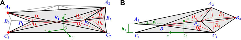
FIGURE 5. Virtual creases of a single-layer Yoshimura-ori structure under bending motion. (A) Panels A1B1P1, A2B1P2, A2B2P2, B1C1P1, B1C2P2, and B2C2P2 are respectively divided into two rigid triangular panels by a virtual crease. (B) Side view of the structure, where the variables α and h1 are denoted.
Similarly, Equations 10a, 10b indicate that during folding, the distances from vertices
Combining Equations 7–10, the coordinates of all vertices can be determined at each step of bending deformation. Based on this, the dihedral angles between adjacent facets can also be calculated based on the law of cosines (exemplified in Equation 6). The obtained dihedral angles are preconditions for evaluating the mechanics of bending motion in Section 4.2.
Based on the model of a single Yoshimura-ori layer, we then investigate the reachable workspace of the Yoshimura-ori structure without considering the effect of gravity. The reachable workspace is affected by the number of layers and the number of segments. Here, as an example, we first examine the reachable workspace of a six-layer Yoshimura-ori segment (Figure 5A). For describing purposes, the vertices of the structure are named as
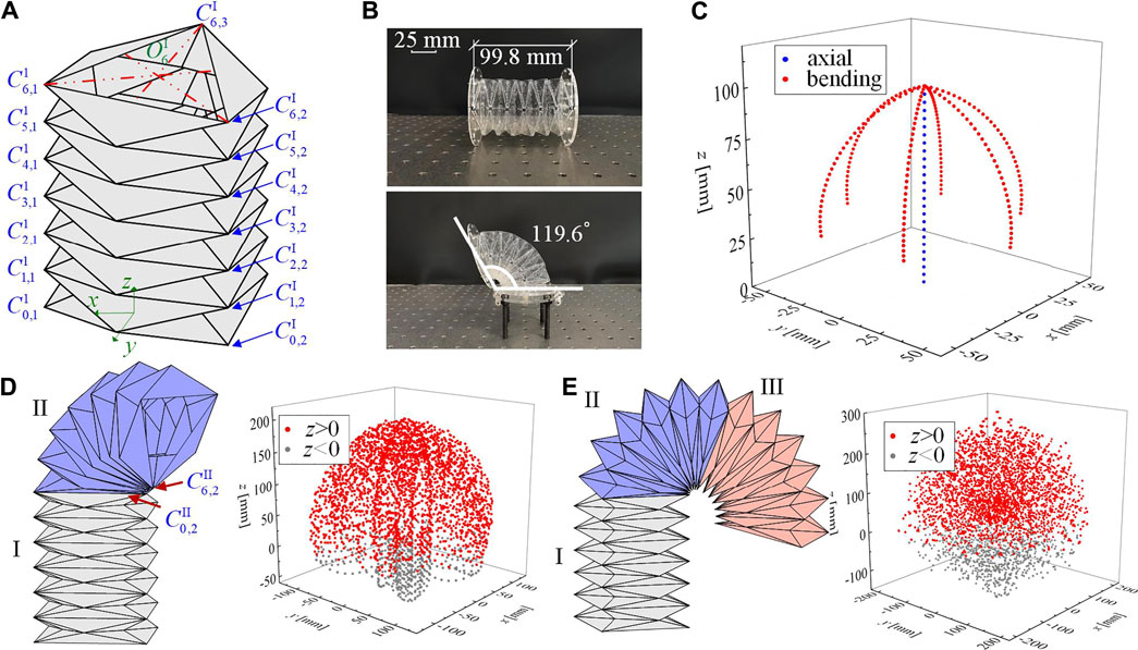
FIGURE 6. Geometry of a multi-layer Yoshimura-ori structure and its reachable workspace. (A) A six-layer Yoshimura-ori structure. (B) A six-layer Yoshimura-ori structure prototype. The top one displays a configuration without deformation, with its original length being 99.8 mm; the bottom one displays the configuration with the maximum reachable bending angle 119.6 °. (C) The reachable workspace of the six-layer Yoshimura-ori structure. (D) The geometry of a two-segment Yoshimura-ori structure and the corresponding reachable workspace. (E) The geometry of a three-segment Yoshimura-ori structure and the corresponding reachable workspace. The excellent 3D deformability is also demonstrated via experiment.
In this research, the deformation of each Yoshimura-ori layer is characterized via the position of the endpoint, which locates at the centroid of the top equilateral triangle. During axial and bending motions, both the top and bottom equilateral triangles remain unchanged. Specifically, the coordinates of the centroid
Particularly, the coordinates of the endpoint
Where
To make a quantitative evaluation, the value of the variable
If involving more segments into the structure, the reachable workspace can be expanded significantly. As an example, we analyze the reachable workspace of a Yoshimura-ori structure with two segments (each segment consists of six layers). The connection between segments is rigid so that the deformation of each segment remains independent. Figure 5D displays a configuration in which segment I is under axial deformation, and segment II is under bending deformation along vertices
To utilize the Yoshimura-ori structure as a robot segment, understanding its mechanical properties is also a necessity. In this section, theoretical derivations of the potential energy profile and the corresponding restoring force are carried out first. After that, quantitative evaluation of the restoring force is performed via experiments, rather than through theoretical efforts. This is because the stiffness of the creases and facets of the origami structure, as well as the stress-free configuration, is always unknown and is difficult to be accurately measured, and there is still a gap between the actual deformation mode and the assumed virtual-crease deformation mode. However, we remark here that the theoretical part is still meaningful. If the physical parameters can be obtained via inverse approaches (e.g., model-based identification (Liu et al., 2018) or data-driven identification (Liu et al., 2019)), the theoretical relations could serve as a useful tool for property prediction and optimization.
With the virtual creases, folding of the Yoshimura-ori structure can be considered as rotations of rigid facets with respect to the elastic hinge-like creases. Hence, the potential energy of the structure with respect to folding can be evaluated. By assigning
In Equation 15,
We then experimentally examine the mechanical behavior of the Yoshimura-ori structure during axial deformation. With the fabrication method introduced in Section 2, four
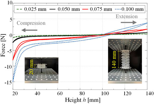
FIGURE 7. Experiments on the mechanical properties of a six-layer Yoshimura-ori structure prototype in the axial direction. The constitutive force-displacement curves are obtained via quasi-static axial compression and extension tests. The insets show two configurations of the prototype with
Similar to the scenario of axial deformation, the potential energy corresponding to the bending motion can also be derived via dihedral angles, lengths of creases, and torsional stiffness
Where the variables
To experimentally examine the relation between the tension force and the bending motion of the Yoshimura-ori structure, a special setup is designed (Figure 8A). Specifically, the Yoshimura-ori structure is clamped between two acrylic plates; the right plate connected with the support is fixed with the bottom platform of the Instron universal testing machine. To measure the force required for bending deformation, an inextensible string is employed to bend the structure by reducing the distance between vertices
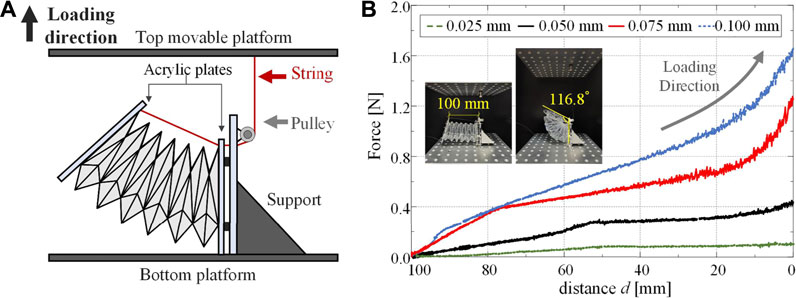
FIGURE 8. Experiments on the mechanical properties of a six-layer Yoshimura-ori structure prototype for bending deformation. (A) Schematic illustration of the setup for the equivalent bending test. (B) The obtained force-displacement curves for the four prototypes with different film thicknesses. Insets show the initial and final configurations of the prototype (i.e.,
Study on the mechanics of Yoshimura-ori structure could provide useful guidelines for robot design and actuator selection. For robot development purposes, folding of the Yoshimura-ori structure has to be robust and consistent, and the restoring forces at the maximum-length and the maximum-angle configurations cannot exceed the actuation limit. These two requirements are sometimes contradictory. With thicker PETE film, the folding process will be more robust and consistent, but meanwhile, it needs a larger actuation force to deform axially or to bend, which will thus restrict the deformability. Hence, compromising is always necessary during robot design. In this research, the PETE film with thickness 0.05 mm is selected to fabricate the robot segment, which corresponds to reasonable magnitudes of the restoring force at the maximum-length and the maximum-angle configurations (0.69 and 0.45 N, respectively), and the obtained origami structure could exhibit robust and consistent folding deformations.
Based on an in-depth understanding of the kinematic and mechanical properties of the Yoshimura-ori structure, we can then integrate the origami structure with axial and bending actuation mechanisms into an earthworm-like robot segment with excellent 3D deformability. Connecting multiple segments into a robot, an earthworm-like robot with 3D locomotion capability is expected.
To acquire active 3D deformability, two types of actuators are incorporated into the robot segment: a pneumatic balloon for axial deformation and four SMA springs for bending deformation. Considering that the Yoshimura-ori structure cannot exhibit radial deformation during folding, additional bristle-like structures made of electromagnets are added to achieve anchoring effects. Figure 9A shows the CAD design of a single segment.
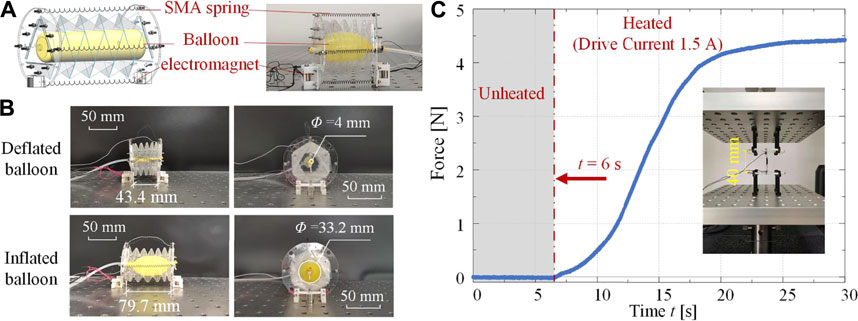
FIGURE 9. CAD design, prototype, and actuation mechanism tests of an earthworm-like robot segment. (A) The CAD design and the photo of a robot segment. (B) Axial actuation tests of a robot segment. By inflating the internal balloon, the segment switches from the axially-contracted state to the axially-extended state. Both the front view and the side view of the prototype are given. (C) The experimental actuation force profile of the SMA spring. The grey area represents the period when no current is applied, and the inset shows the test setup.
In detail, for each robot segment, a
Note that due to the introduction of actuation components, the kinematical properties of the robot segment will be different from the Yoshimura-ori structure segment, including the length of the prototype at the deformation-free state, the maximum bending angle, etc.
Figure 9A also displays the photo of a robot segment prototype. It weighs only 29.8 g. The mechanical properties of the Yoshimura-ori structure have been comprehensively studied in Section 4. Here, the effectiveness of the actuators is demonstrated.
First, axial actuation of the robot segment through the pneumatic balloon is tested. The air pressure
Second, the mechanical properties of the SMA spring are evaluated. The SMA spring is fixed on the Instron universal testing machine and its initial length is set to be 40 mm. At
To vividly demonstrate the 3D deformability, a prototype with three robot segments is tested. To test the deformability, one end of the prototype is fixed on the support; we use a camera to record the deformation process and measure the geometry. Figures 10A–D illustrates the axial contraction, axial extension, up-contraction, and left-contraction of the three-segment Yoshimura-ori structure prototype. At the axially-contracted and the axially-extended configurations, the axial length of the prototype is 160.9 and 273.9 mm, respectively. Hence, the net axial deformation of the three-segment prototype is 113.0 mm, which is 60.23% of its original length (160.9 mm). Such excellent axial deformability is desirable in earthworm-like robot development for achieving fast locomotion. Note that theoretically, the structure can be fully contracted to a very small height; while practically, its reachable axial deformation is restricted by the actuators. At the up-contracted and left-contracted configurations, the bending angle can be up to 42.4° and 54.2°, respectively, which is also favorable to robot development for achieving effective turning and rising motions. Note that the bending angle of the up-contracted configuration is smaller than that of the left-contracted configuration, which is induced by the effect of gravity.
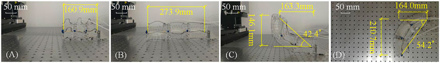
FIGURE 10. (A–D) Photos show the axial contraction, axial extension, up-contraction, and left-contraction of the three-segment Yoshimura-ori structure prototype.
Based on the designed robot segments a five-segment origami-based earthworm-like robot is prototyped by connecting five robot segments in series (Figure 11A). A camera is set at the head of the robot to capture the video of the working environment. The entire robot is 410 mm in length and 331.6 g in weight, and the weight-length ratio is only 0.81 g/mm. Comparing with other earthworm-like robots (e.g., 76.0 g/mm for the continuous meshworm robot (Boxerbaum et al., 2012), 1.39 g/mm for the earthworm-like robot with a spring-steel-belt body (Fang et al., 2014), and 1.27 g/mm for the underground earthworm-like explorer (Omori et al., 2009)), the robot has a very low weight-length ratio, which is beneficial for 3D locomotion.
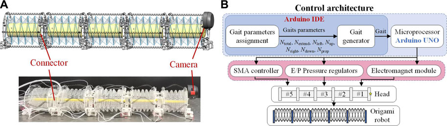
FIGURE 11. Prototype of a five-segment Yoshimura-ori-based earthworm-like robot and its control architecture. (A) CAD design and photo of the five-segment origami-based earthworm-like robot prototype. (B) Gait control architecture of the earthworm-like metameric robot.
Particularly, note that the weight of the robot forepart (consisting of a robot segment and the camera) is about 1.76 N, which is lower than the maimum actuation force of the SMA spring (4.39 N), indicating the feasibility for lifting the robot head. Moreover, the nominal attraction force of a single electromagnet is 10 N; with multiple embedded electromagnets and with a proper locomotion gait, the robot is possible to hold its weight (3.25 N), anchor with the magnetic media, and climb a wall, providing that the contact surface is not too smooth. However, further investigation on the locomotion performance by incorporating the robot weight, the electromagnet attraction force, and the friction coefficient is necessary, which is also an important part of our ongoing research.
Learning from the earthworm’s locomotion mechanism, i.e., the retrograde peristalsis wave, periodic gaits are proposed for the robotic locomotion. Fundamentally, a locomotion gait is defined as a sequence of the robot segment states with respect to the time, with the initial state being identical to the final state (Fang et al., 2014). Specifically, seven states of the robot segment are defined to construct the locomotion gait. Table 1 lists the seven states and the corresponding driving patterns.
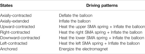
TABLE 1. States and driving patterns of the robot segments.
For the developed Yoshimura-ori based earthworm-like robot, seven parameters are needed to construct the locomotion gait, namely, the total number of the segments
The segments with inflatable balloons (
Figure 11B display the architecture of the robot gait controller, which consists of a computer (with Arduino Software IDE), Arduino UNO hardware, power supply, SMA controllers, and E/P Pressure Regulators. Inputting the seven gait parameters to the controller, admissible gaits of different locomotion can be generated. Gait signal will then be transmitted to voltage to the E/P Pressure Regulators, electromagnet, and SMA controllers, and finally actuate the SMA springs and balloon. However, the locomotion control of this robot is different from the traditional earthworm-like robot.
Based on the robot prototype shown in Figure 11A and the gait controller provided in Figure 11B, locomotion tests are carried out on a horizontal iron plane. The robot’s locomotion is recorded by cameras, from which the trajectories of the robot head can be extracted and analyzed. To demonstrate the predicted 3D locomotion capability of the robot, Figure 12 shows the video snapshots of four locomotion tests, which include three types of locomotion, namely, rectilinear locomotion, turning locomotion, and rising locomotion.
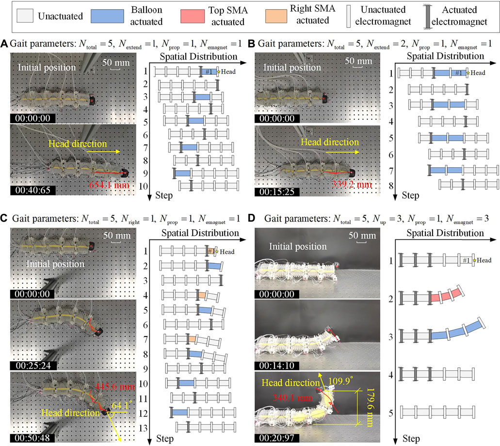
FIGURE 12. 3D Locomotion tests, demonstrating via the snapshots and the extracted trajectory of the robot locomotion are demonstrated, as well as the corresponding locomotion gaits. (A) Rectilinear locomotion. (B) Rectilinear locomotion with another gait. (C) Right turning of the robot. (D) Rising up of the robot head. For these four locomotion tests, the adopted gait parameters are also listed.
Figure 12A (Supplementary Video S1) displays the snapshots for a rectilinear locomotion test and the corresponding gait (demonstrated as the state sequence of the robot segments). For the gait used in this test, each period of the robotic locomotion contains 10 steps, and only one segment is extended (i.e., the balloon is actuated) in every other step. Specifically, in the first step, the balloon in the head segment (segment #1) is pneumatized in 0.8 s, and the rear electromagnet of segment #1 is activated, which can push the robot head forward. In the second step, the front electromagnet of segment #1 is actuated, and the balloon of segment #1 is deflated in 1.1 s, which would pull the rest of the robot forward. In the following steps, actuation of the balloon and the electromagnet as a whole will propagate backward, generating a retrograde peristalsis wave, similar to the earthworm’s wave. With such a gait, the robot moves 327.1 mm in a period of 20.33 s, with an average speed of 16.09 mm/s. Figure 11A shows the snapshot at 40.65 s, where a 654.1 mm displacement is achieved by the robot. With five segments, the metameric robot could be equipped with more than one rectilinear locomotion gaits. Figure 12B (Supplementary Video S2) depicts another rectilinear locomotion with a different gait. The main difference is that two balloons are pneumatized in every other step. Hence, the robot needs only eight steps to finish a period, and the robot achieves faster locomotion with an average speed of 22.24 mm/s (i.e., move 339.2 mm in a period of 15.25 s).
In the third test, we demonstrate the planar locomotion, and the corresponding gait control is shown in Figure 12C (Supplementary Video S3). In this case, as an example, the three anterior segments are asked to perform right-contraction for turning purposes, and the two posterior segments are asked to perform axial extension for propelling purposes. In the first step, the right SMA spring of segment #1 is heated and contract in 4 s, and its rear electromagnet is energized so that the robot head turns to the right. In the second step, the rear electromagnet of segment #1 keeps energized, and the balloon of segment #1 is inflated to push the robot head forward right. In the third step, the anterior electromagnet of segment #1 is activated, and the balloon of segment #1 is deflated to pull the rest of the robot forward right. In the following steps, actuation of the balloon, the SMA spring, and the electromagnet as a whole will propagate backward. With such a gait, the robot can move 445.6 mm in two periods (50.48 s), with an average speed of 8.83 mm/s, and the robot head turns an angle of 64.1°.
The last test is the rising locomotion test, which is significantly distinct from the rectilinear and planar locomotion. For the gait used in this test, each period of the robotic locomotion contains five steps (Figure 12D (Supplementary Video S4)). In the first step, the last three electromagnets at the rear of the robot are energized to firmly anchor with the ground so that the robot can remain stable when the head is raised. In the second step, the top SMA springs of segments #1, #2, and #3 are heated and contract in 13 s, so that the robot head would be lifted. In the third step, the balloons in segments #1, #2, and #3 are inflated, which pushes the robot head upward. In the next step, the balloons are deflated and the robot head is lowered. Finally, all actuators are deactivated and the robot returns to its initial state. With such a gait, the robot can raise its head to 179.6 mm, and the rising angle could reach 109.9°.
Inspired by earthworms’ outstanding locomotion capability in various environment, earthworm-like locomotion robot has received extensive attention in many fields. While rich robot designs have been proposed for achieving rectilinear and planar locomotion, earthworm-like robots with excellent 3D locomotion capability are still immature. The inherent limitations in terms of the size, weight, and deformability of conventional earthworm-like robots greatly restrict the possibility of achieving 3D locomotion. As a result, aiming at expanding the locomotion capability from planar to spatial, an origami-based earthworm-like robot with unique 3D locomotion capability is designed and prototyped. The major innovation lies in the synthesis of the bio-inspired robot design principles, the extraordinary folding-induced origami kinematics, and the hybrid actuation mechanism. Among diverse origami patterns, the Yoshimura-ori structure stands out due to its simple crease pattern design, cylinder shape, and excellent axial and bending deformability, which is very similar to the bellow. However, the Yoshimura-ori structures possess some additional advantages that the bellows do not have. First, the Yohimura-ori structures have better designability due to the rich origami design space, and modification of the design can be achieved relatively easily by altering the crease patterns. Second, the Yoshimura-ori structure can be made of thin 2D materials (e.g. PETE film), which is very light in weight. On the other hand, the bellows used in robot are usually fabricated by 3D printing (Sheng et al., 2020) or silicone molding (Tang et al., 2020), which are more heavier in weight and diminish the 3D deformability of the robot.
After showing the geometry design and fabrication of the Yoshimura structure, we first establish an equivalent kinematic model of the single-layer Yoshimura-ori structure to understand its non-rigid folding motion. By assuming a uniform distribution of the bending and axial deformation in multiple Yoshimura-ori layers, we can then derive the reachable workspace of a six-layer Yoshimura-ori, which is made up of seven tracks (six curved tracks achieved by bending motion, and one straight track achieved by axial deformation). By increasing the number of segments, the furthest reachable distance of the endpoint can be significantly expanded, and the reachable positions in the workspace would become denser. Based upon the folding kinematics and by prescribing torsional stiffness to the creases, mechanical analyses are also performed to uncover the constitute force-displacement profiles during axial and bending deformations. Axial extension and bending tests indicate that the restoring forces for axial and bending deformations can be effectively tailored by changing the film thickness, which, therefore, provide necessary guidelines for robot design.
After understanding the kinematics and mechanics of the Yoshimura-ori structure, a five-segment earthworm-like locomotion robot is developed by synthesizing the origami structure and a hybrid actuation mechanism. Specifically, the Yoshimura-ori structure is made of 0.05 mm-thick PETE film, and the hybrid actuation mechanism consists of pneumatic balloons, SMA springs, and electromagnets. Before testing the five-segment robot, the effectiveness of a single robot segment in axial and bending deformations is first verified experimentally, and the extraordinary 3D deformability is demonstrated via a three-segment prototype. After that, the five-segment origami robot is evaluated. Comparing with conventional earthworm-like robots, the newly-developed robot prototype shows unique merits in terms of the weight-length ratio (which is only 0.81 g/mm) and the 3D deformation ability. To acquire 3D earthworm-like locomotion, gait control is proposed by learning from the earthworm’s retrograde peristalsis wave. Without loss of generality, various locomotion gaits can be generated by prescribing seven gait parameters. Experiments indicate that in addition to the rectilinear locomotion, the developed robot could perform effective left/right turning and rising locomotion, which, therefore, successfully enhancing the robot locomotion capability from 2D to 3D.
Overall, this research proposes a new type of earthworm-like locomotion robot based on the Yoshimura-ori structure. By integrating the excellent origami reconfigurability with the hybrid actuation mechanism, the obtained origami robot segment is featured with unique active 3D deformability, which, as a result, endows the earthworm-like robot with excellent 3D locomotion capability. The outcomes of this research could provide useful guidelines for the development of origami robots and worm-like locomotion robots. Note that a detailed mechanics model of the locomotion robot has not been established in this research, and the effects of gravity, payloads, and frictional resistance on the robot locomotion performance are not considered. These issues are of key importance in predicting and optimizing the robot performance, and they constitute a significant part of our ongoing work.
The raw data supporting the conclusions of this article will be made available by the authors, without undue reservation.
HF and JX designed research. QZ and HF designed the robot, performed the analyses, carried out the experiments, and analyzed the data. HF and JX supervised the research. QZ and HF worked on the manuscript.
This research was supported by the National Key Research and Development Project of China (Grant No. 2020YFB1312900), the National Natural Science Foundation of China (Grants No. 11932015, 11902078), and the Shanghai Rising-Star Program under Grant No. 20QA1400800.
The authors declare that the research was conducted in the absence of any commercial or financial relationships that could be construed as a potential conflict of interest.
All claims expressed in this article are solely those of the authors and do not necessarily represent those of their affiliated organizations, or those of the publisher, the editors and the reviewers. Any product that may be evaluated in this article, or claim that may be made by its manufacturer, is not guaranteed or endorsed by the publisher.
The Supplementary Material for this article can be found online at: https://www.frontiersin.org/articles/10.3389/frobt.2021.738214/full#supplementary-material
Adams, W., Sridar, S., Thalman, C. M., Copenhaver, B., Elsaad, H., and Polygerinos, P. (2018). “Water Pipe Robot Utilizing Soft Inflatable Actuators,” in 2018 IEEE International Conference on Soft Robotics, RoboSoft, Livorno, Italy, 24–28 April, 2018, 321–326. doi:10.1109/robosoft.2018.8404939
Bhovad, P., Kaufmann, J., and Li, S. (2019). Peristaltic Locomotion Without Digital Controllers: Exploiting Multi-Stability in Origami to Coordinate Robotic Motion. Extreme Mech. Lett. 32, 100552. doi:10.1016/j.eml.2019.100552
Boxerbaum, A. S., Shaw, K. M., Chiel, H. J., and Quinn, R. D. (2012). Continuous Wave Peristaltic Motion in a Robot. Int. J. Robotics Res. 31, 302–318. doi:10.1177/0278364911432486
Cai, J., Deng, X., Xu, Y., and Feng, J. (2015). Motion Analysis of a Foldable Barrel Vault Based on Regular and Irregular Yoshimura Origami. J. Mech. Robot. 8, 021017. doi:10.1115/1.4031658
Calderón, A. A., Ugalde, J. C., Chang, L., Cristóbal Zagal, J., and Pérez-Arancibia, N. O. (2019). An Earthworm-Inspired Soft Robot with Perceptive Artificial Skin. Bioinspir Biomim 14, 056012. doi:10.1088/1748-3190/ab1440
Daltorio, K. A., Boxerbaum, A. S., Horchler, A. D., Shaw, K. M., Chiel, H. J., and Quinn, R. D. (2013). Efficient Worm-Like Locomotion: Slip and Control of Soft-Bodied Peristaltic Robots. Bioinspir Biomim 8, 035003. doi:10.1088/1748-3182/8/3/035003
Deng, B., Chen, L., Wei, D., Tournat, V., and Bertoldi, K. (2020). Pulse-Driven Robot: Motion Via Solitary Waves. Sci. Adv. 6, eaaz1166. doi:10.1126/sciadv.aaz1166
Deng, D., and Chen, Y. (2015). Origami-Based Self-Folding Structure Design and Fabrication Using Projection Based Stereolithography. J. Mech. Des. Trans. ASME 137, 021701. doi:10.1115/1.4029066
Edwards, C. A., and Bohlen, P. J. (1996). Biology and Ecology of Earthworms. 3rd Edn. London: Springer Science & Business Media.
Fang, D., Shang, J., Luo, Z., Lv, P., and Wu, G. (2018a). Development of a Novel Self-Locking Mechanism for Continuous Propulsion Inchworm In-Pipe Robot. Adv. Mech. Eng. 10, 1–11. doi:10.1177/1687814017749402
Fang, H., Chu, S. A., Xia, Y., and Wang, K. W. (2018b). Programmable Self-Locking Origami Mechanical Metamaterials. Adv. Mater. 30, e1706311. doi:10.1002/adma.201706311
Fang, H., Li, S., Ji, H., and Wang, K. W. (2017a). Dynamics of a Bistable Miura-Origami Structure. Phys. Rev. E 95, 052211. doi:10.1103/PhysRevE.95.052211
Fang, H., Li, S., Wang, K. W., and Xu, J. (2015a). Phase Coordination and Phase-Velocity Relationship in Metameric Robot Locomotion. Bioinspir Biomim 10, 066006. doi:10.1088/1748-3190/10/6/066006
Fang, H., Zhang, Y., and Wang, K. W. (2017b). Origami-Based Earthworm-Like Locomotion Robots. Bioinspir Biomim 12, 065003. doi:10.1088/1748-3190/aa8448
Fang, H., Wang, C., Li, S., Wang, K. W., and Xu, J. (2015b). A Comprehensive Study on the Locomotion Characteristics of a Metameric Earthworm-Like Robot. Multibody Syst. Dyn. 35, 153–177. doi:10.1007/s11044-014-9428-5
Fang, H., Wang, C., Li, S., Xu, J., and Wang, K. W. (2014). “Design and Experimental Gait Analysis of a Multi-Segment In-Pipe Robot Inspired by Earthworm’s Peristaltic Locomotion,” in Proceedings of SPIE 9055, Bioinspiration, Biomimetics, and Bioreplication 2014, 90550H, San Diego, March 8, 2014. doi:10.1117/12.2044262
Fields, M. A., Haas, E., Hill, S., Stachowiak, C., and Barnes, L. (2009). “Effective Robot Team Control Methodologies for Battlefield Applications,” in 2009 IEEE/RSJ International Conference on Intelligent Robots and Systems, IROS 2009, St. Louis, October 10–15, 2009 (IEEE), 5862–5867. doi:10.1109/iros.2009.5354188
Ge, J. Z., Calderón, A. A., and Pérez-Arancibia, N. O. (2017). “An Earthworm-Inspired Soft Crawling Robot Controlled by Friction,” in 2017 IEEE International Conference on Robotics and Biomimetics (ROBIO), Macau, December 5–8, 2017, 834–841. doi:10.1109/robio.2017.8324521
Harigaya, K., Adachi, K., Yanagida, T., Yokojima, M., and Nakamura, T. (2013). “Development of a Peristaltic Crawling Robot for Sewer Pipe Inspection,” in 2013 IEEE International Conference on Mechatronics, ICM 2013, Vicenza, February 27–March 1, 2013(IEEE), 267–272. doi:10.1109/icmech.2013.6518547
Horchler, A. D., Kandhari, A., Daltorio, K. A., Moses, K. C., Ryan, J. C., Stultz, K. A., et al. (2015). Peristaltic Locomotion of a Modular Mesh-Based Worm Robot: Precision, Compliance, and Friction. Soft Robotics 2, 135–145. doi:10.1089/soro.2015.0010
Hu, W., Lum, G. Z., Mastrangeli, M., and Sitti, M. (2018). Small-Scale Soft-Bodied Robot with Multimodal Locomotion. Nature 554, 81–85. doi:10.1038/nature25443
Isaka, K., Tsumura, K., Watanabe, T., Toyama, W., Sugesawa, M., Yamada, Y., et al. (2019). Development of Underwater Drilling Robot Based on Earthworm Locomotion. IEEE Access 7, 103127–103141. doi:10.1109/access.2019.2930994
Kandhari, A., Huang, Y., Daltorio, K. A., Chiel, H. J., and Quinn, R. D. (2018). Body Stiffness in Orthogonal Directions Oppositely Affects Worm-like Robot Turning and Straight-Line Locomotion. Bioinspir Biomim 13, 026003. doi:10.1088/1748-3190/aaa342
Kim, B., Lee, M. G., Lee, Y. P., Kim, Y., and Lee, G. (2006). An Earthworm-Like Micro Robot Using Shape Memory alloy Actuator. Sensors Actuators A: Phys. 125, 429–437. doi:10.1016/j.sna.2005.05.004
Li, S., Fang, H., Sadeghi, S., Bhovad, P., and Wang, K. W. (2019). Architected Origami Materials: How Folding Creates Sophisticated Mechanical Properties. Adv. Mater. 31, 1805282. doi:10.1002/adma.201805282
Li, S., and Wang, K. W. (2015). Fluidic Origami with Embedded Pressure Dependent Multi-Stability: A Plant Inspired Innovation. J. R. Soc. Interf. 12, 20150639. doi:10.1098/rsif.2015.0639
Liu, Z., Fang, H., Wang, K.-W., and Xu, J. (2018). A Parameter Identification Method for Continuous-Time Nonlinear Systems and its Realization on a Miura-Origami Structure. Mech. Syst. Signal Process. 108, 369–386. doi:10.1016/j.ymssp.2018.02.024
Liu, Z., Fang, H., and Xu, J. (2019). Identification of Piecewise Linear Dynamical Systems Using Physically-Interpretable Neural-Fuzzy Networks: Methods and Applications to Origami Structures. Neural Networks 116, 74–87. doi:10.1016/j.neunet.2019.04.007
Majidi, C. (2014). Soft Robotics: A Perspective-Current Trends and Prospects for the Future. Soft Robotics 1, 5–11. doi:10.1089/soro.2013.0001
Omori, H., Hayakawa, T., and Nakamura, T. (2008). “Locomotion and Turning Patterns of a Peristaltic Crawling Earthworm Robot Composed of Flexible Units,” in 2008 IEEE/RSJ International Conference on Intelligent Robots and Systems, IROS, Nice, September 22–26, 2008 (IEEE), 1630–1635. doi:10.1109/iros.2008.4650980
Omori, H., Nakamura, T., and Yada, T. (2009). An Underground Explorer Robot Based on Peristaltic Crawling of Earthworms. Ind. Robot 36, 358–364. doi:10.1108/01439910910957129
Onal, C. D., Tolley, M. T., Wood, R. J., and Rus, D. (2015). Origami-Inspired Printed Robots. Ieee/asme Trans. Mechatron. 20, 2214–2221. doi:10.1109/tmech.2014.2369854
Paez, L., Agarwal, G., and Paik, J. (2016). Design and Analysis of a Soft Pneumatic Actuator with Origami Shell Reinforcement. Soft Robotics 3, 109–119. doi:10.1089/soro.2016.0023
Pagano, A., Yan, T., Chien, B., Wissa, A., and Tawfick, S. (2017). A Crawling Robot Driven by Multi-Stable Origami. Smart Mater. Struct. 26, 94007. doi:10.1088/1361-665x/aa721e
Quillin, K. J. (1999). Kinematic Scaling of Locomotion by Hydrostatic Animals: Ontogeny of Peristaltic Crawling by the Earthworm Lumbricus Terrestris. J. Exp. Biol. 202, 661–674. doi:10.1242/jeb.202.6.661
Rodríguez, E., Kypson, A. P., Moten, S. C., Nifong, L. W., and Chitwood, W. R. (2006). Robotic Mitral Surgery at East Carolina University: A 6 Year Experience. Int. J. Med. Robotics Comput. Assist. Surg. 2, 211–215. doi:10.1002/rcs.80
Saito, K., Tsukahara, A., and Okabe, Y. (2015). New Deployable Structures Based on an Elastic Origami Model. J. Mech. Des. 137, 021402. doi:10.1115/1.4029228
Seok, S., Onal, C. D., Cho, K.-J., Wood, R. J., Rus, D., and Kim, S. (2013). Meshworm: A Peristaltic Soft Robot with Antagonistic Nickel Titanium Coil Actuators. Ieee/asme Trans. Mechatron. 18, 1485–1497. doi:10.1109/tmech.2012.2204070
Sheng, X., Xu, H., Zhang, N., Ding, N., Zhu, X., and Gu, G. (2020). Multi-Material 3D Printing of Caterpillar-Inspired Soft Crawling Robots with the Pneumatically Bellow-Type Body and Anisotropic Friction Feet. Sensors Actuators A: Phys. 316, 112398. doi:10.1016/j.sna.2020.112398
Silverberg, J. L., Evans, A. A., McLeod, L., Hayward, R. C., Hull, T., Santangelo, C. D., et al. (2014). Using Origami Design Principles to Fold Reprogrammable Mechanical Metamaterials. Science 345, 647–650. doi:10.1126/science.1252876
Song, C.-W., Lee, D.-J., and Lee, S.-Y. (2016). Bioinspired Segment Robot with Earthworm-Like Plane Locomotion. J. Bionic Eng. 13, 292–302. doi:10.1016/s1672-6529(16)60302-5
Tanaka, Y., Ito, K., Nakagaki, T., and Kobayashi, R. (2012). Mechanics of Peristaltic Locomotion and Role of Anchoring. J. R. Soc. Interf. 9, 222–233. doi:10.1098/rsif.2011.0339
Tang, Z., Lu, J., Wang, Z., Chen, W., and Feng, H. (2020). Design of a New Air Pressure Perception Multi-Cavity Pneumatic-Driven Earthworm-Like Soft Robot. Auton. Robot 44, 267–279. doi:10.1007/s10514-019-09892-x
Tanise, Y., Taniguchi, K., Yamazaki, S., Kamata, M., Yamada, Y., and Nakamura, T. (2017). “Development of an Air Duct Cleaning Robot for Housing Based on Peristaltic Crawling Motion,” in IEEE/ASME International Conference on Advanced Intelligent Mechatronics, AIM, Munich, July 3–7, 2017, 1267–1272. doi:10.1109/aim.2017.8014192
Trivedi, D., Rahn, C. D., Kier, W. M., and Walker, I. D. (2008). Soft Robotics: Biological Inspiration, State of the Art, and Future Research. Appl. Bionics Biomech. 5, 99–117. doi:10.1080/11762320802557865
Wang, K., Yan, G., Jiang, P., and Ye, D. (2008). A Wireless Robotic Endoscope for Gastrointestine. IEEE Trans. Robot. 24, 206–210. doi:10.1109/tro.2008.915418
Wu, H., Fang, H., Chen, L., and Xu, J. (2020). Transient Dynamics of a Miura-Origami Tube During Free Deployment. Phys. Rev. Appl. 14, 034068. doi:10.1103/physrevapplied.14.034068
Yang, K., Xu, S., Shen, J., Zhou, S., and Xie, Y. M. (2016). Energy Absorption of Thin-Walled Tubes with Pre-Folded Origami Patterns: Numerical Simulation and Experimental Verification. Thin-Walled Structures 103, 33–44. doi:10.1016/j.tws.2016.02.007
Yang, W., Yang, C., Zhang, R., and Zhang, W. (2019). “A Novel Worm-Inspired Wall Climbing Robot with Sucker-Microspine Composite Structure,” in 2018 3rd International Conference on Advanced Robotics and Mechatronics (ICARM), Singapore, July 18–20, 2018, 744–749. doi:10.1109/ICARM.2018.8610723
Yasuda, H., and Yang, J. (2015). Reentrant Origami-Based Metamaterials with Negative Poisson's Ratio and Bistability. Phys. Rev. Lett. 114, 185502–185505. doi:10.1103/PhysRevLett.114.185502
Zarrouk, D., and Shoham, M. (2012). Analysis and Design of One Degree of freedom Worm Robots for Locomotion on Rigid and Compliant Terrain. J. Mech. Des. Trans. ASME 134, 1–9. doi:10.1115/1.4005656
Zhan, X., Fang, H., Xu, J., and Wang, K.-W. (2019). Planar Locomotion of Earthworm-Like Metameric Robots. Int. J. Robotics Res. 38, 1751–1774. doi:10.1177/0278364919881687
Zhang, Q., Fang, H., and Xu, J. (2020). Programmable Stopbands and Supratransmission Effects in a Stacked Miura-Origami Metastructure. Phys. Rev. E 101, 42206. doi:10.1103/physreve.101.042206
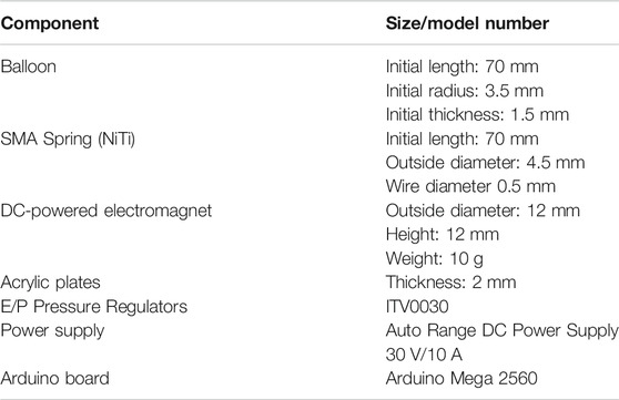
TABLE A1. The detailed parameters of the robot segment’s component.
Keywords: bio-inspired robot, origami kinematics, origami robot, peristaltic locomotion, locomotion gait
Citation: Zhang Q, Fang H and Xu J (2021) Yoshimura-origami Based Earthworm-like Robot With 3-dimensional Locomotion Capability. Front. Robot. AI 8:738214. doi: 10.3389/frobt.2021.738214
Received: 08 July 2021; Accepted: 09 August 2021;
Published: 20 August 2021.
Edited by:
Arijit Ghosh, Johns Hopkins University, United StatesReviewed by:
Deepak Trivedi, General Electric, United StatesCopyright © 2021 Zhang, Fang and Xu. This is an open-access article distributed under the terms of the Creative Commons Attribution License (CC BY). The use, distribution or reproduction in other forums is permitted, provided the original author(s) and the copyright owner(s) are credited and that the original publication in this journal is cited, in accordance with accepted academic practice. No use, distribution or reproduction is permitted which does not comply with these terms.
*Correspondence: Jian Xu, eHVqaWFuQHRvbmdqaS5lZHUuY24=
Disclaimer: All claims expressed in this article are solely those of the authors and do not necessarily represent those of their affiliated organizations, or those of the publisher, the editors and the reviewers. Any product that may be evaluated in this article or claim that may be made by its manufacturer is not guaranteed or endorsed by the publisher.
Research integrity at Frontiers
Learn more about the work of our research integrity team to safeguard the quality of each article we publish.