- 1Department of Control Engineering and Automation, Faculty of Electrical and Electronic Engineering, Ho Chi Minh City University of Technology (HCMUT), Ho Chi Minh City, Vietnam
- 2Vietnam National University Ho Chi Minh City, Ho Chi Minh City, Vietnam
- 3Department of Engineering Sciences, University of Agder (UiA), Grimstad, Norway
Collaborative robots (or cobots) are robots that can safely work together or interact with humans in a common space. They gradually become noticeable nowadays. Compliant actuators are very relevant for the design of cobots. This type of actuation scheme mitigates the damage caused by unexpected collision. Therefore, elastic joints are considered to outperform rigid joints when operating in a dynamic environment. However, most of the available elastic robots are relatively costly or difficult to construct. To give researchers a solution that is inexpensive, easily customisable, and fast to fabricate, a newly-designed low-cost, and open-source design of an elastic joint is presented in this work. Based on the newly design elastic joint, a highly-compliant multi-purpose 2-DOF robot arm for safe human-robot interaction is also introduced. The mechanical design of the robot and a position control algorithm are presented. The mechanical prototype is 3D-printed. The control algorithm is a two loops control scheme. In particular, the inner control loop is designed as a model reference adaptive controller (MRAC) to deal with uncertainties in the system parameters, while the outer control loop utilises a fuzzy proportional-integral controller to reduce the effect of external disturbances on the load. The control algorithm is first validated in simulation. Then the effectiveness of the controller is also proven by experiments on the mechanical prototype.
1 Introduction
Cobots are robots intended for direct collaborative work with a human operator (Wannasuphoprasit et al., 1997; Peshkin et al., 2001). Cobots appear and support humans in many situations in our daily life, e.g., search and rescue missions (Govindarajan et al., 2016), surveillance and inspection (Donadio et al., 2018; Brito et al., 2020), medical support (Mokaram et al., 2017), etc. One aspect, which makes cobots different from traditional robots, is the capability to mitigate the damage caused by the unpredictable collision in dynamic shared working space. There are various methods to achieve this capability, such as using force/torque sensors (Li et al., 2020), using elastic joints, or using a collision detection algorithm without changing a robot’s physical structure and adding external sensors (Xiao et al., 2018). Using elastic joints is one of the most common methods because it is efficient and low-priced. Conventional actuators are designed by following the traditional principle of “the stiffer the better” (Pratt and Williamson, 1995; Vanderborght et al., 2013). Due to having high force bandwidth, stiff actuators are suitable for position and speed control, and trajectory tracking tasks in isolated environments. However, in unknown environments, these stiff actuators can be damaged by undesired collision. In addition, most low-cost electric motors have to operate at high speed to obtain high torque density. Therefore, to achieve low-speed output for position control tasks, gear reduction is used at the expense of introducing friction, noise, backlash, and torque ripple (Pratt and Williamson, 1995). On the other hand, elastic joints, with compliant motion and shock load absorption characteristics, are developed to tackle these challenges. Shock tolerance of the elastic joints in unstructured environments is enhanced thanks to the elastic components working as a low-pass shock filter. Furthermore, energy storage capability, power output and force sensing are also enhanced (Paine et al., 2015). In spite of numerous advantages, controlling the position and velocity of elastic joints is more challenging than conventional stiff actuators due to the oscillation of elastic components. In addition, disturbance forces can cause the elastic joint to deviate from its original position.
The importance of human-robot interaction cannot be overstated when it comes to cobots, especially when direct physical interaction with humans is considered, i.e., rehabilitation robots. In this perspective, a design of an elastic actuator with springs having different stiffness is introduced in Yu et al. (2013c). The proposed design consists of a servomotor, a ball screw, a torsional spring between the motor and the ball screw, and a set of translational springs between the ball screw nut and the external load. The soft translational springs are used to handle the low force operation and reduce output impedance, stiction, and external shock load. When the translational springs are fully compressed, the torsional spring has a high effective stiffness and enhances the system bandwidth. This design is quite compact. The dynamic modelling and analysis of the proposed actuator is also demonstrated. In (Yu et al. (2013a), this same type of elastic actuator is adopted to design a knee-ankle-foot robot. Successively, a force control approach is presented for the same actuator in Yu et al. (2013b). First, two dynamical actuator methods are introduced based on different force ranges. Second, for the low force range, an optimal control with friction compensation and disturbance rejection, which is augmented by a feedforward control, is presented. The proposed optimal control strategy is further extended to high force ranges. Third, to manage the transition between low and high force control, a switching control technique is provided. The controller is further enhanced in Yu et al. (2015). Human interaction compensation, friction compensation, and a disturbance observer are the primary components of the improved controller. When operating in human-in-charge mode, such a control system allows the robot to achieve low output impedance, while precise force tracking is obtained when operating in force control mode.
In line with these research trends, a newly-designed low-cost, open-source design of an elastic joint is proposed in this work to give researchers a solution that is economical, highly adaptable, and quick to manufacture. The design is based on our previously proposed layout for the modules of Serpens (Sanfilippo et al., 2019a; Sanfilippo et al., 2019b), a low-cost, open-source and highly compliant multi-purpose modular snake robot. Based on the newly designed elastic joint, the design of a 2-DOF robot arm for safe human-robot interaction is also proposed in this article. The robot components are 3D-printed by using Fused Deposition Modelling (FDM) manufacturing technology, thus making the rapid-prototyping process very economical and quick. The real 3D-printed robot arm is shown in Figure 1, together with the actuator model. Moreover, a decentralised control structure is introduced. Separate controllers are implemented for each joint. The control algorithm is based on a two-feedback loops position control mechanism: an adaptive control is designed in the inner loop to stabilise the system and deal with uncertainties, while a fuzzy controller is considered for the outer loop to eliminate the influence of external force/torque. Then, the controller is validated in simulation with (MATLAB, 2018) and tested in reality with the 3D-printed prototype. The simulation and experiment results show that the decentralised controller could stabilise and precisely control the elastic joint in normal and disturbed conditions.
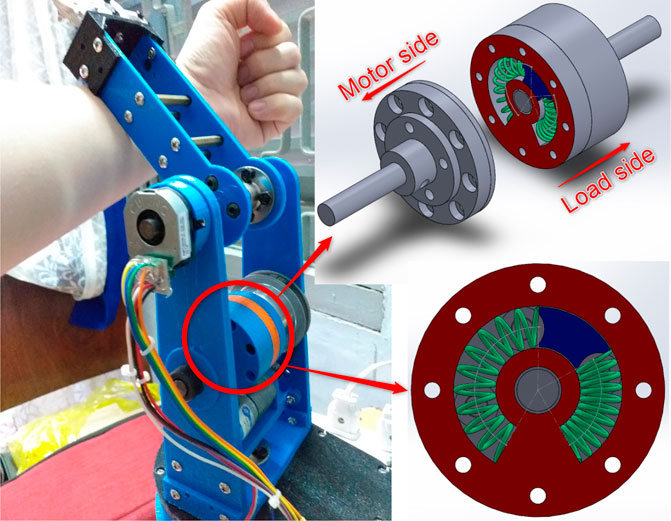
FIGURE 1. The proposed 2-DOF robot arm with elastic joints for safe human-robot interaction. The real 3D-printed prototype and the 3D model of the joint are shown, respectively.
The paper is organised as follows. A review of the related research work is given in Section 2. In Section 3, we focus on the description of the proposed control algorithm. In Section 4, the physical prototype of the 2-DOF robot arm is presented. In Section 5, related simulation results are outlined. In Section 6, the results of experiments on the physical prototype are shown. Finally, conclusions and future works are discussed in Section 7.
2 Related Research Work
2.1 Related Control Methods
The advantages of elastic joints are first outlined by Pratt and Williamson’s research (Pratt and Williamson, 1995), where a proportional-integral-derivative (PID) control scheme was proposed. Similarly, proportional-derivative (PD) controllers with on-line gravity compensation are considered in De Luca et al. (2005), Zollo et al. (2007). The global asymptotic stability of these control laws is demonstrated via Lyapunov’s argument and La Salle’s theorem. Another alternative approach is based on robust controllers with a disturbance observer (DOB) (Kim and Chung, 2015). In Talole et al. (2010), a combination of a feedback linearisation-based controller for the trajectory tracking problem and an extended state observer for uncertainty and states estimation is considered. Feedback linearisation and robust integral of sign of error (RISE) methods for controlling position are proposed in Yin et al. (2016). Specifically, the dynamics of the actuator is first feedback linearised, then a RISE method is applied to adapt the system model to uncertainties. A model reference adaptive control approach is implemented in Losey et al. (2016) to adapt to uncertainties in system parameters, while the adoption law is demonstrated using Lyapunov’s theory. In Pérez-Ibarra et al. (2017), a
2.2 Related Mechanical Design
Elastic elements play a very important role in elastic joints. They are responsible for absorbing unexpected collision and storing elastic energy. The elastic elements can be springs and can have different shapes (as shown in Figure 2). Springs in elastic joints can be classified into torsion spring and extension/compression spring. In (Pratt et al., 1997, 2002; for; Human and Cognition, 2020), a pair of extension/compression springs are used, as shown in Figure 2A. In (Sanfilippo et al., 2019a), two springs are bent to fit into a compact housing, as shown in Figure 2B. Beside conventional springs, there are some custom designs of the elastic element. Some examples are shown in Figure 2.
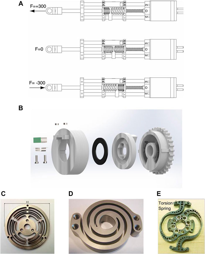
FIGURE 2. Different designs of the elastic element (A) series elastic actuator SEA23-23 from Yobotics (Pratt et al., 1997, 2002) (B) series elastic actuator from Serpens robot (Sanfilippo et al., 2019a) (C) a torsional elastic element of wearable robots for knee assistance (Carpino et al., 2012) (D) LOPES′ spring (Lagoda et al., 2010) (E) NASA Valkyrie’s spring (Paine et al., 2015; Radford et al., 2015).
To amplify the torque and reduce the speed of a motor, gearing systems are adopted. Besides the common spur gears, some special types of gear are also utilised in elastic joints. Strain wave gearing, also known as harmonic gearing, can be applied, e.g., (Negrello et al., 2015; Wang et al., 2017; Sergi et al., 2012). This mechanism consists of three basic components: a wave generator, a flex spline, and a circular spline. The advantages of the harmonic gearing mechanism are no backlash, high compactness, lightweight, high gear ratios in a small volume, and coaxial input and output shafts. In the research of Meng (Wang et al.,2015; Wang et al., 2017), a nonlinear series elastic joint with variable stiffness is presented. There are two motors and a harmonic gearing mechanism in this design. One motor is connected to the wave generator, while the other motor is used to change the stiffness preset, and the link is attached to the flex spline. Planetary gearing system is also utilised in elastic joints, e.g., (Lee and Oh, 2016; Plooij et al., 2016). The advantages of the planetary gearing mechanism are compactness, high efficiency, low backlash, high torque density (i.e., high torque-to-mass ratio), and coaxial input and output shafts. In Lee and Oh (2016), good control performance is achieved while the size is still compact. The motor shaft is connected to the Sun gear, the torsional spring is connected to the ring gear, the load is attached to the carrier and the planet gears combine these three parts. One side of the spring and the motor is attached to a fixed base. In Plooij et al. (2016), a BIdirectional Clutched Parallel Elastic Actuator (BIC-PEA) is introduced. The mechanism contains a planetary differential, a torsion spring, and two brakes. It is stated that BIC-PEA design can save up to 65% of the energy consumption in some specific tasks.
3 Control Algorithm
In this section, a mathematical model of the considered elastic joint system is introduced. A novel control algorithm was previously designed by our research group and proposed in (Hua et al., 2019). This control algorithm is summarised in this section. For further details, the reader is referred to (Hua et al., 2019).
3.1 Mathematical Model
The schematic diagrams of the elastic actuator are illustrated in Figure 3. There are two gears with gear ratio
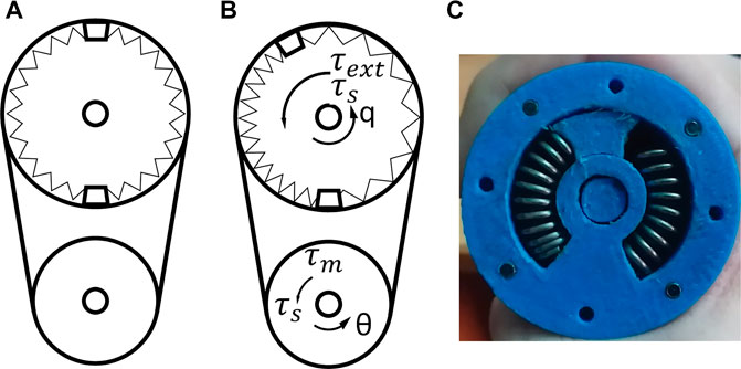
FIGURE 3. Elastic joint system (A) without external force/torque (B) compressed/tensed by external action (C) compression of the springs on the real prototype.
The whole system is affected by disturbances from the motor (
Eq. 1 shows the relationship on the motor-side between the motor torque, the spring torque and the motor angular position. The spring torque,
3.2 Controller Design
The proposed control algorithm diagram is presented in Figure 4. The objective of this work is to develop a controller that can track the desired load angular position when considering external disturbances on the load and uncertainties in system parameters. To achieve this objective, two separate types of controllers are utilised for the motor-side and the load-side, respectively. For the load-side, we propose using a Fuzzy PI Controller (FPIC) to reduce the effect of external disturbances on the load. The considered external disturbances are the forces/torques caused by undesired collisions when operating in unknown environments. The output of the FPIC is used as the desired angular position of the motor. For the motor-side, a Model Reference Adaptive Controller (MRAC) is used to cope with uncertainties in system parameters. The uncertain system parameters could be the inertia of the load or the stiffness of the spring. The idea is inspired to a previous research of (Losey et al., 2016). The advantage of combining the FPIC and the MRAC controllers is the possibility of achieving independence with respect to imprecise system parameters. In previous works (Losey et al., 2016), the motor angular position is prioritised more than the load position because the target is force control. The contribution of the paper is that a robust position control algorithm for the load position is proposed. In addition, a better spring model is given with the damping coefficient added.
3.2.1 Fuzzy PI Controller
An FPIC is applied to the load-side to cope with the effect of external disturbances on the elastic joint system. A fuzzy controller is not based on a strict mathematical model and is widely used to solve problems under uncertain environments, with high nonlinearities (Al-Odienat and Al-Lawama, 2008). A fuzzy algorithm is a control method based on fuzzy logic, which uses “fuzzy inference rules” instead of “equations”. These fuzzy inference rules may come from experience of a human expert in controlling a specific object, or in other cases, from the understanding of dynamics and behaviour of the target plant. A fuzzy controller can be combined with a conventional PID controller to obtain a fuzzy PI, a fuzzy PD or a fuzzy PID controller. The fuzzy PI type controller is known to be more practical than fuzzy PD types because it is difficult for the fuzzy PD to remove steady state errors (Rao et al., 2010). The relationship between the input and the output in a conventional PI controller is expressed in the following equation:
where,
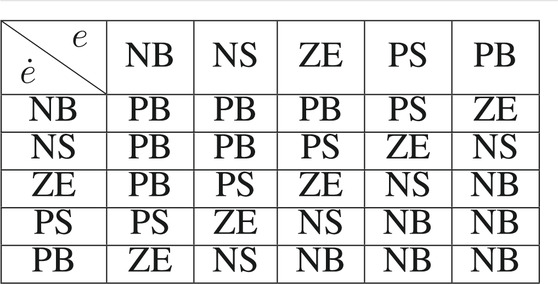
A fuzzy PI controller can be obtained by combining Eq. 5 with the fuzzy controller. Inputs of the FPIC are the feedback error (e) and the change of this error (
The membership functions for the input and the output are shown in Figure 5A,B, in which
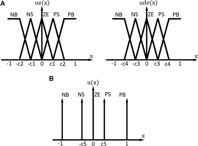
FIGURE 5. Fuzzy membership functions (A) input membership functions (B) output membership functions.
3.2.2 Model Reference Adaptive Controller
Although there are various control algorithms available from the past literature (Pratt and Williamson, 1995; Talole et al., 2010; Losey et al., 2016; Penzlin et al., 2019), uncertainties in system parameters can lead to instability in many cases. Adaptive controllers are developed to overcome this problem. An MRAC is an important adaptive controller typology in which the desired response is expressed by a reference model. The adaptation law modifies the system parameters based on the difference between the output of the real system and the output of the reference model. In this article, Lyapunov’s stability theory is applied to design the adaptation law. Lyapunov’s stability criterion states that a system,
Firstly, the control law is derived. The motor-side system equations can be rewritten by using Eqs. 1, 2 (ignoring the motor-side external disturbance
In Eq. 9, the state matrix A, input matrix B and state vector
The motor-side system equations have the form of a second-order system, so the reference model is a second-order system model with the desired signal
In Eq. 11, the state matrix
A general control law for the system with state Eq. 9 is:
Parameters with hats (
If perfect estimation of parameters is obtained, we have
Eqs. 15, 16 are called compatible conditions. If these conditions are satisfied and we have perfect estimation of parameters, then the controller 13 can yield perfect tracking of the reference model. From these equations, the controller optimal matrices
Based on the above Eqs. 17, 18 for the controller optimal matrices, the matrices M and L can be approximated as:
Secondly, the error equation is determined. The feedback error, which is the difference between the output of the real system and the output of the reference model, is determined as:
The derivative of error is determined as:
where, it should be noted that:
Thirdly, the adaption law can be obtained by applying Lyapunov’s stability theory. A Lyapunov function is introduced as:
where, P is a symmetric positive definite matrix and γ is a learning rate. The function V is positive definite. The derivative of V is obtained as:
where,
then the derivative of Lyapunov function
In this article, due to their symmetry, the matrices P and Q are chosen as it follows:
where,
In real applications, discrete system equations are utilized instead of continuous ones. By approximately discretising the reference system Eq. 9, we obtain:
4 Physical Prototype
4.1 Mechanical Design
In this section, the mechanical design of the elastic joint and the robot arm are described. The mechanical components of the elastic joint are shown in Figure 6A. A 3D view of the same parts is illustrated in Figure 6B, while the assembled view of the actuator is illustrated in Figure 6C–E. The mechanism can be separated into load side and motor side. The motor side mechanism includes an 8 mm metal shaft, an 8 mm metal flange, a flange extension, a cover, and a driving joint (component 9, 8, 7, 6, 5 in Figure 6A, respectively). The load side mechanism includes an 8 mm metal shaft, a cap, an 8 mm metal flange, and a compliant joint (component 1, 2, 3, 4 in Figure 6A, respectively). The shafts are connected to the other parts by the flanges. The flange on the motor side is connected to the flange extension and the flange extension is connected to the cover and the motor side driving joint. The motor side driving joint has space to place two springs with 8 mm outer diameter. When the motor rotates, the springs are compressed. This will create an elastic force on the compliant joint. The load side shaft is connected to the joint through the flange. The shaft is kept in place by a cap. In our work, two extension/compression springs are chosen because they form a symmetrical configuration. In addition, the extension/compression type of spring is used instead of torsion spring because it is more durable and can bear a larger force.
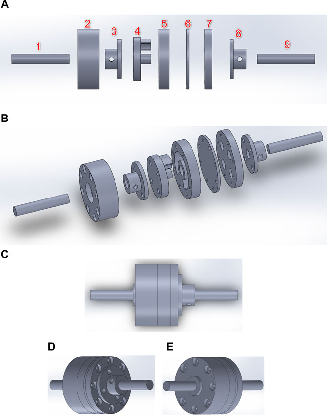
FIGURE 6. Mechanical design of the elastic joint (A) exploded view. Load side: (1) load side shaft, (2) cap, (3) 8 mm-shaft flange, (4) load side compliant joint. Motor side: (5) motor side driving joint, (6) cover, (7) flange extension, (8) 8 mm-shaft flange, (9) motor side shaft (B) 3D view of the elastic joint (C) assembled view of the design of the elastic joint (D) view from the motor side (E) view from the load side.
Based on the newly introduced actuator, the design of the 2-DOF elastic robot arm is shown in Figure 7. The joints of the robot arm are revolute joints. The motor and the elastic joints are connected by pulleys and belts. The transmission ratio from the motor to the actuator is 4:1 (the pulley of the motor has 20 teeth and the pulley of the actuator has 80 teeth).
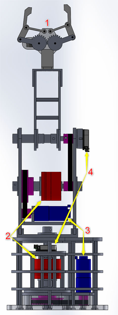
FIGURE 7. Mechanical design of the 2-DOF robot arm with elastic joints: (1) Gripper, (2) elastic joints, (3) GA25 DC motors, (4) AMT20 encoders.
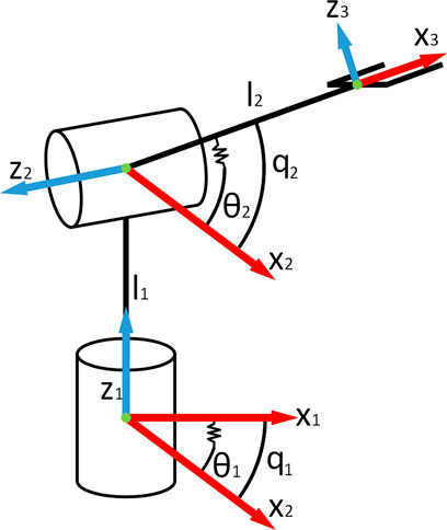
The simplified model of the robot arm is shown in Figure 8. The Denavit-Hartenberg table is shown in Table 2. The angles are in radian and the lengths are in meter. From this table, the corresponding transformation matrices are formed, as shown in Eq. 30.
4.2 Hardware Design
In this section, the hardware used in the robot arm is presented. The motor used in the robot arm is the GA25 DC motor (XYTmotor, 2020). It is a 12 V DC motor with a 4 mm shaft and a two channels encoder attached. The gearbox transmission ratio is chosen as 217:1. The encoder for the load side is the AMT-20 encoder (devices, 2020) from CUI Devices. It has incremental and absolute encoders in a compact package. The incremental encoder has three channels (A, B, and Z). The absolute encoder has 12 bits of absolute position information with Serial Peripheral Interface (SPI) communication. The microcontroller used is the STM32F446RE on the STM32 Nucleo board (Stmicroelectronics, 2020).
4.3 Software Design and Architecture
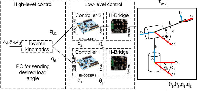
The software design is described in this section. The concept of modularity is applied to the control architecture. Each joint is independent, being controlled by a self-reliant slave controller, which directly communicates with the master controller running on a personal computer (PC). Each slave controller communicates with the PC through a Universal Serial Bus (USB) port on the board. Figure 9 shows the diagram of the control architecture. Each STM32 board has timer peripherals, which are used to capture the encoder signals. The timers are also configured to be Pulse width modulation (PWM) output to control the motors through H-bridges (nhatbon, 2020). The control/update rate of the controller is 100 Hz (10 milliseconds). The presented framework is a multi-layer architecture that includes the following layers: High-level control layer: it considers the control of the overall manipulator, it includes kinematics according to the corresponding DOFs. Low-level control layer: it considers the control of the single joints. This makes it possible to use the proposed approach for robotic arms with different DOFs.
5 Simulation Results
In this section, simulations are outlined with the aim of validating the proposed control algorithm for the considered elastic joint. The simulations are conducted on (MATLAB, 2018). This software is chosen because of its ability to quickly constructing simulation models and validating control schemes. The responses of the elastic joint with step and sinusoidal wave inputs are presented. The effect of external torque and disturbances on the whole elastic system is also illustrated. The system parameters used in the simulation are shown in Table 3.
5.1 Response of the Load-Side System With Step and Sine Desired Signals Without External Torque
The response of the load-side system in normal condition is illustrated in this section. Step and sine responses are shown in Figure 10. In these figures, blue dashed lines are desired inputs and red solid lines are load angular positions. The unstable stage at the beginning of the simulation is the learning phase of the MRAC. The results show that the proposed controller has relatively fast response and small error.
5.2 Response of the Motor-Side System With Step and Sine Desired Signals Without External Torque
The response of the motor-side system in normal condition is presented in this section. Step and sine responses are shown in Figure 11A,B, respectively. The reference model and the MRAC parameters are shown in Table 4tbl4. The system parameters are modified based on the adaption law (Eq. 26) to reduce the error between reference model and real motor response. The adaption law is designed using Lyapunov’s approach. This has an advantage: arbitrary large values of the learning rate coefficient γ can be used (Åström and Wittenmark, 2013).
The damping coefficient ξ of the reference model is chosen to be critically damped (
5.3 Response of the Load and Motor-Side System With External Torque to the Step Desired Signal
In this section, the effect of the disturbance on the elastic joint and the efficiency of the proposed algorithm is demonstrated. The disturbance signal affecting the load side is a sine wave signal with an amplitude of five radian and a cycle time of 0.5 s. This signal is applied to each joint. This is equivalent to the vibrations often occurring in elastic joints. The sine response of the load-side system and the motor-side system is shown in Figure 12A,B, respectively. The motor control voltage is shown in Figure 12C. In the proposed two-loop controller, the FPIC is adopted on the load side to reduce the influence of external disturbances and the MRAC is adopted on the motor side to deal with uncertainties. When there is an external torque, the desired motor angular position is adjusted by the FPIC, so that the error between the desired load angular position and the real load angular position goes to zero. As shown in Figure 12B, the motor angular position changes when the external torque appears and the influence of this external torque is eliminated.
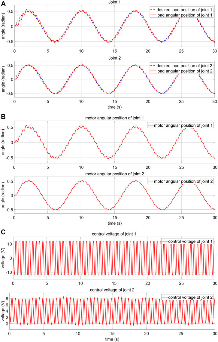
FIGURE 12. Response of the FPIC-MRAC of the robot arm with external disturbance (A) load-side response (B) motor-side response (C) motor control voltage.
To show more evidently the effectiveness of the proposed control algorithm, a standard PID controller is applied and its results are compared. As shown in Figure 13A,B, the responses of the PID controller and the FPIC-MRAC controller are similar in normal condition. However, as shown in Figure 13B and Figure 12A, the response of the FPIC-MRAC controller is significantly better than the PID controller in the presence of external disturbance.
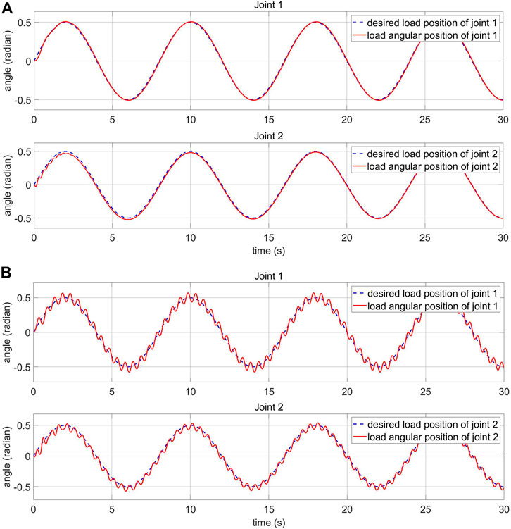
FIGURE 13. Load-side response of the PID controller of the robot arm (A) in normal condition (B) with external disturbance.
5.4 Response of the Load and Motor-Side System With Human-Machine Interaction
The impact of human-machine interaction on the elastic joints is presented in this section. The load side response and the control voltage are shown in Figure 14. The simulated human-machine interaction of joint 1 appears from the second 20 to 30 and from 40 to 45. The simulated human-machine interaction of joint 2 appears from the second 10 to 20 and from 30 to 40. The collected data outline that despite being affected by the disturbance, the controller can adjust the voltage to keep the system stable.
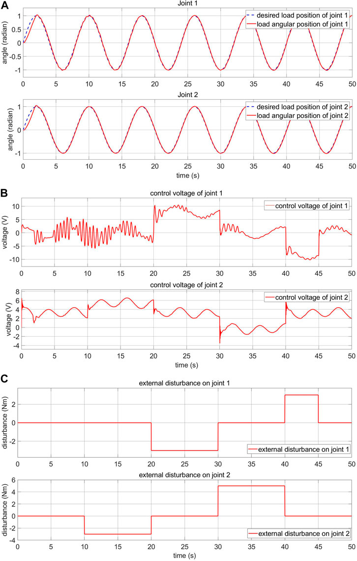
FIGURE 14. Load-side response and control voltage of the FPIC-MRAC with human-machine interaction (A) load-side response (B) control voltage (C) external disturbance.
6 Experiments
In this section, experiments are conducted to verify the effectiveness of the control algorithm on the mechanical prototype of the robot arm. The experiments consist of joints’ response and trajectory tracking. It should be noted that, in the simulation, the elastic joints are controlled directly by changing the voltage, as shown in Figure 12C. However, in the experiments, the elastic joints are controlled by torque produced from the motor which is proportional to the current injected by the H-bridge. This current is dependent on the applied voltage, which is controlled by adjusting the duty cycle of the PWM pulse.
6.1 Experiment in Normal Condition
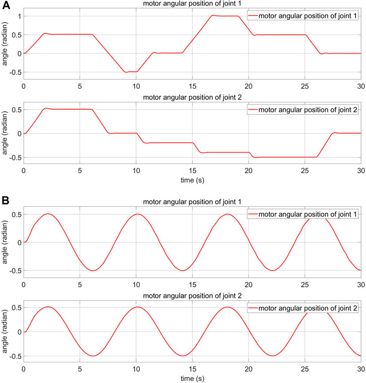
In this subsection, experiment results related to the control of the real 2-DOF robot arm with elastic joints in the normal condition are presented. The normal condition is when the robot arm is not disturbed by the external torque. The joint angle response and control voltage are demonstrated. There are two input signal types: sinusoidal and square waveforms. The sinusoidal waveform input has an amplitude of 0.5 rad and a cycle time of 8 s. The square waveform input has an amplitude of 0.5 rad and a cycle time of 8 s. The data is collected within 50 s.
Figure 15; Supplement Figure S1 show the angle response and the control voltage of joint 1 and joint 2, respectively, in normal condition with the sinusoidal waveform input. The figures demonstrate that the decentralised control algorithm works as expected. As shown in Figure 15A, the absolute value of the positive peak of the motor angle is larger than the negative peak. This is due to a small manufacturing defect in the actuator: the spring on one side is stiffer than the spring on the other side. Despite this fact, it is clear that the controller still tracks the desired load angle.
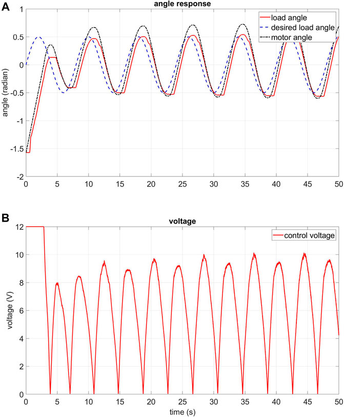
FIGURE 15. Experiment: angle response and control voltage of the FPIC-MRAC of joint 1 in normal condition, sine waveform input (A) angle response of joint 1 (B) control voltage of joint 1.
The angle response and the control voltage of joint 1 and joint 2 are shown in Supplement Figures S2, S3, respectively, in normal condition with the square waveform input. These figures demonstrate that the decentralised control algorithm also works well in this situation. The error decreases to smaller than 10° after just a few seconds.
6.2 Experiment When There Is Unexpected Torque
In this subsection, the experiment results of the real 2-DOF robot arm with elastic joints in presence of disturbances are presented. The joint angle response and control voltage are demonstrated. The sinusoidal waveform input has an amplitude of 0.5 rad and a cycle time of 8 s. The data is collected within 50 s. The external disturbance is created by randomly holding the robot arm by hand while it is operating. This imitates the unexpected collision with a human operator while coexisting in a shared work-space.The angle response and the control voltage of joint 1 and joint 2 in disturbance condition are shown in Supplement Figures S4, S5, respectively. These figures demonstrate that the decentralised control algorithm can stabilise the system when there is unexpected torque. In addition, if the absolute value of the deviation between the motor angle and the load angle is larger than 30° (0.523,599 radians), the motor will stop. This value can be tuned appropriately, which means that safety can be guaranteed.
6.3 Trajectory Tracking Experiment in Normal Condition
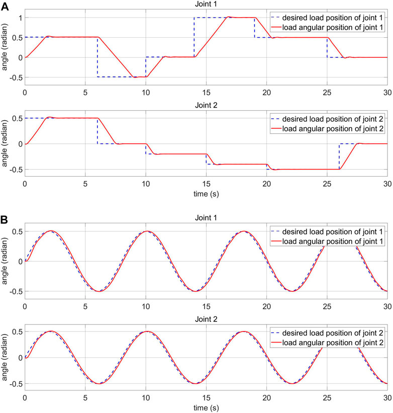
In this subsection, trajectory tracking experiment results of the elastic robot arm in the normal condition are demonstrated. A sequence of images of the experiment is illustrated in Supplement Figure S6. The initial position is when
6.4 Trajectory Tracking Experiment When There Is Unexpected Torque
In this subsection, trajectory tracking experimental results of the elastic robot arm when there is an unexpected torque are demonstrated. A sequence of images from the experiment is shown in Supplement Figure S8. The initial position is when
7 Conclusion
A newly designed elastic joint was presented in this work based on our previuous design, which was previously introduced in Sanfilippo et al. (2019a), Sanfilippo et al. (2019b). Based on the developed elastic joint, a 2-DOF robot arm with elastic behaviour for safe human-robot interaction was also presented. The mechanical prototype can be 3D-printed by using Fused Deposition Modelling (FDM) manufacturing technology, thus making the rapid-prototyping process very economical and fast. Moreover, a position control algorithm was introduced to control each joint of the arm. The control algorithm is based on a 2-loops control mechanism. In particular, the inner control loop is designed as a model reference adaptive controller (MRAC) to deal with uncertainties in the system parameters, while the outer control loop utilises a fuzzy proportional-integral controller (FPIC) to reduce the effect of external disturbances on the load. Preliminary simulations were carried out in Matlab to validate the potential of the proposed control algorithm. Successively, the effectiveness of the controller was also proven by conducting experiments with the mechanical prototype.
As future work, the possibility of replacing the DC motors with brushless DC (BLDC) motors will be considered. Due to having high torque density, BLDC motors will make it possible to achieve a more compact actuation system. In addition, as shown in Figure 9, the proposed controller has a decentralised design. This means that each joint has its own separated controller, both in hardware and software. Therefore, the number of DOFs can be expanded and tested easily in the future. Furthermore, the stability analysis at the system level will also be considered.
Moreover, the possibility of realising a digital-twin of the presented robot will be considered to enable researchers for designing and prototyping different control algorithms. In this perspective, the integration with an open-source software framework will be investigated. To achieve this, there are different robotic frameworks and middleware available in recent years (Tsardoulias and Mitkas, 2017). However, the Robot Operating System (ROS) (Quigley et al., 2009) has emerged as a de facto standard for robot software architecture in the research community. In conjunction with ROS, Gazebo 3D simulator (Koenig and Howard, 2004) can be adopted to accurately and efficiently simulate robots in complex indoor and outdoor environments. Therefore, these tools will be considered to realise a digital-twin of the presented robot.
In the future, the design of reliable low-level control algorithms for the proposed elastic joints could be also relevant for other robotic systems, such as snake like robots similar to Serpens (Sanfilippo et al., 2019a), which is developed by our research group. This technology may be essential to enable the achievement of perception-driven obstacle-aided locomotion (POAL) (Sanfilippo et al., 2016, 2017, 2018).
Data Availability Statement
The raw data supporting the conclusion of this article will be made available by the authors, without undue reservation.
Author Contributions
Conceptualisation, TH and FS; methodology, TH and FS; software, TH; validation, TH, FS and HN; formal analysis, TH and FS; investigation, TH and FS; resources, HN; data curation, TH; writing—original draft preparation, TH and FS; writing—review and editing, TH, FS and HN; visualisation, TH; supervision, FS and HN; project administration, FS and HN; funding acquisition, FS and HN. All authors have read and agreed to the published version of the manuscript.
Funding
We acknowledge the support of time and facilities from Ho Chi Minh City University of Technology (HCMUT), VNU-HCM and from the Top Research Centre Mechatronics (TRCM), University of Agder, Norway, for this study.
Conflict of Interest
The authors declare that the research was conducted in the absence of any commercial or financial relationships that could be construed as a potential conflict of interest.
Publisher’s Note
All claims expressed in this article are solely those of the authors and do not necessarily represent those of their affiliated organizations, or those of the publisher, the editors and the reviewers. Any product that may be evaluated in this article, or claim that may be made by its manufacturer, is not guaranteed or endorsed by the publisher.
Supplementary Material
The Supplementary Material for this article can be found online at: https://www.frontiersin.org/articles/10.3389/frobt.2021.679304/full#supplementary-material
References
Al-Odienat, A. I., and Al-Lawama, A. A. (2008). The Advantages of Pid fuzzy controllers over the conventional types. Am. J. Appl. Sci. 5, 653–658. doi:10.3844/ajassp.2008.653.658
Åström, K. J., and Wittenmark, B. (2013). Adaptive Control. North Chelmsford, Massachusetts: Courier Corporation.
Brito, T., Queiroz, J., Piardi, L., Fernandes, L. A., Lima, J., and Leitão, P. (2020). A machine learning Approach for collaborative robot smart manufacturing inspection for quality control systems. Proced. Manufacturing 51, 11–18. doi:10.1016/j.promfg.2020.10.003
Carpino, G., Accoto, D., Sergi, F., Luigi Tagliamonte, N., and Guglielmelli, E. (2012). A novel compact torsional spring for series elastic Actuators for Assistive wearable robots. J. Mech. Des. 134 (121002), 1–10. doi:10.1115/1.4007695
De Luca, A., Siciliano, B., and Zollo, L. (2005). PD control with on-line gravity compensation for robots with elastic joints: theory and experiments. Automatica 41, 1809–1819. doi:10.1016/j.automatica.2005.05.009
devices, C. (2020). 28 Mm, 12 Bit, Single-Turn, Absolute, Spi Interface, Capacitive Modular Encoder (Lake Oswego: CUI devices).
Donadio, F., Frejaville, J., Larnier, S., and Vetault, S. (2018). “Artificial intelligence and collaborative robot to improve Airport operations,” in Online Engineering & Internet of Things (Springer) (Springer, Cham). doi:10.1007/978-3-319-64352-6_91973–986.
Govindarajan, V., Bhattacharya, S., and Kumar, V. (2016). “Human-robot collaborative topological exploration for search and rescue Applications,” in Distributed Autonomous Robotic Systems (Berlin, Germany: Springer), 17–32. doi:10.1007/978-4-431-55879-8_2
Hua, T. M., Sanfilippo, F., and Helgerud, E. (2019). “A robust two-feedback loops Position control Algorithm for compliant low-cost series elastic Actuators,” in 2019 IEEE International Conference on Systems, Man and Cybernetics (SMC) (New Jersey, United States: IEEE). 2384–2390. doi:10.1109/smc.2019.8913845
Human, F. I., and Cognition, M. (2020). The institute for Human & Machine Cognition (Ihmc) Pioneers Technologies Aimed at Leveraging and Extending Human Capabilities (Ocala: IHMC).
Kaya, K. D., and Çetin, L. (2017). Adaptive state feedback controller design for a rotary series elastic Actuator. Trans. Inst. Meas. Control. 39, 61–74. doi:10.1177/0142331215600779
Kim, M. J., and Chung, W. K. (2015). Disturbance-observer-based Pd control of flexible joint robots for Asymptotic convergence. IEEE Trans. Robot. 31, 1508–1516. doi:10.1109/tro.2015.2477957
Koenig, N., and Howard, A. (2004). “Design And use Paradigms for gazebo, an open-source multi-robot simulator,” in Proc. of the IEEE/RSJ International Conference on Intelligent Robots and Systems (IROS), Sendai, Japan (IEEE). vol. 3, 2149–2154.
Lagoda, C., Schouten, A. C., Stienen, A. H., Hekman, E. E., and van der Kooij, H. (2010). Design of an electric series elastic Actuated joint for robotic gait rehabilitation training. In 2010 3rd IEEE RAS & EMBS International Conference on Biomedical Robotics and Biomechatronics. New Jersey, United States: IEEE. 21–26. doi:10.1109/biorob.2010.5626010
Lee, C., and Oh, S. (2016). Configuration and Performance Analysis of a compact Planetary geared elastic Actuator. In IECON 2016-42nd Annual Conference of the IEEE Industrial Electronics Society. (New Jersey, United States: IEEE). 6391–6396. doi:10.1109/iecon.2016.7793816
Li, W., Han, Y., Wu, J., and Xiong, Z. (2020). Collision detection of robots based on a force/torque sensor at the bedplate. IEEE/ASME Trans. Mechatronics 25, 2565–2573. doi:10.1109/tmech.2020.2995904
Losey, D. P., Erwin, A., McDonald, C. G., Sergi, F., and O'Malley, M. K. (2016). A time-domain Approach to control of series elastic Actuators: Adaptive torque and Passivity-based impedance control. Ieee/asme Trans. Mechatron. 21, 2085–2096. doi:10.1109/tmech.2016.2557727
Mokaram, S., Aitken, J. M., Martinez-Hernandez, U., Eimontaite, I., Cameron, D., Rolph, J., et al. (2017). A ROS-integrated API for the KUKA LBR iiwa collaborative robot * *The Authors Acknowledge support from the EPSRC Centre for Innovative Manufacturing in Intelligent Automation, in undertaking this research work under grant reference number EP/I033467/1, and the University of Sheffield Impact, Innovation and Knowledge Exchange grant "Human Robot Interaction Development". Equipment has been provided under the EPSRC Great Technologies Capital Call: Robotics and Autonomous Systems. IFAC-PapersOnLine 50, 15859–15864. doi:10.1016/j.ifacol.2017.08.2331
Negrello, F., Garabini, M., Catalano, M. G., Malzahn, J., Caldwell, D. G., Bicchi, A., et al. (2015). A modular compliant Actuator for emerging high Performance and fall-resilient humanoids. In 2015 IEEE-RAS 15th International Conference on Humanoid Robots (Humanoids). New Jersey, United States: IEEE). 414–420. doi:10.1109/humanoids.2015.7363567
Paine, N., Mehling, J. S., Holley, J., Radford, N. A., Johnson, G., Fok, C.-L., et al. (2015). Actuator control for the nasa-jsc valkyrie humanoid robot: A decoupled dynamics Approach for torque control of series elastic robots. J. Field Robotics 32, 378–396. doi:10.1002/rob.21556
Penzlin, B., Enes Fincan, M., Li, Y., Ji, L., Leonhardt, S., and Ngo, C. (2019). “Design and Analysis of a clutched Parallel elastic Actuator,” in Actuators (Basel, Switzerland, Multidisciplinary Digital Publishing Institute), vol. 8, 67. doi:10.3390/act8030067
Pérez-Ibarra, J. C., Alarcón, A. L. J., Jaimes, J. C., Ortega, F. M. E., Terra, M. H., and Siqueira, A. A. (2017). Design and Analysis of force control of a series elastic Actuator for impedance control of an Ankle rehabilitation robotic Platform. In 2017 American Control Conference (ACC). (New Jersey, United States: IEEE). 2423–2428.
Peshkin, M. A., Colgate, J. E., Wannasuphoprasit, W., Moore, C. A., Gillespie, R. B., and Akella, P. (2001). Cobot Architecture. IEEE Trans. Robot. Automat. 17, 377–390. doi:10.1109/70.954751
Plooij, M., Wisse, M., and Vallery, H. (2016). Reducing the energy consumption of robots using the bidirectional clutched Parallel elastic Actuator. IEEE Trans. Robot. 32, 1512–1523. doi:10.1109/tro.2016.2604496
Pratt, G. A., Williamson, M. M., Dillworth, P., Pratt, J., and Wright, A. (1997). “Stiffness isn’t everything,” in Experimental Robotics IV (Berlin, Germany: Springer), 253–262.
Pratt, G. A., and Williamson, M. M. (1995). Series elastic Actuators. In Proc. of the IEEE/RSJ International Conference on Intelligent Robots and Systems, Pittsburgh, PA (IEEE). vol. 1, 399–406.
Pratt, J., Krupp, B., and Morse, C. (2002). Series elastic Actuators for high fidelity force control. Ind. Robot: Int. J 29 (3), 234–241. doi:10.1108/01439910210425522
Quigley, M., Conley, K., Gerkey, B., Faust, J., Foote, T., Leibs, J., et al. (2009). “ROS: an open-source robot operating system,” in Proc. of the IEEE International Conference on Robotics and Automation (ICRA), workshop on open source software, Kobe, Japan (IEEE). vol. 3, 5.
Radford, N. A., Strawser, P., Hambuchen, K., Mehling, J. S., Verdeyen, W. K., Donnan, A. S., et al. (2015). Valkyrie: NASA's First Bipedal Humanoid Robot. J. Field Robotics 32, 397–419. doi:10.1002/rob.21560
Rao, K. G., Reddy, B. A., and Bhavani, P. D. (2010). Fuzzy Pi and integrating type fuzzy Pid controllers of linear, nonlinear and time-delay systems. Int. J. Comp. Appl. 1, 41–47. doi:10.5120/144-264
Sanfilippo, F., Azpiazu, J., Marafioti, G., Transeth, A. A., Stavdahl, Ø., and Liljebäck, P. (2016). A review on Perception-driven obstacle-Aided locomotion for snake robots. In Proc. of the 14th International Conference on Control, Automation, Robotics and Vision (ICARCV), Phuket, Thailand. 1–7. doi:10.1109/icarcv.2016.7838565
Sanfilippo, F., Azpiazu, J., Marafioti, G., Transeth, A., Stavdahl, Ø., and Liljebäck, P. (2017). Perception-Driven Obstacle-Aided Locomotion for Snake Robots: The State of the Art, Challenges and Possibilities †. Appl. Sci. 7, 336. doi:10.3390/app7040336
Sanfilippo, F., Helgerud, E., Stadheim, P. A., and Aronsen, S. L. (2019b). Serpens, a low-cost snake robot with series elastic torque-controlled Actuators and a screw-less Assembly mechanism. In Proc. of the IEEE 5th International Conference on Control. Beijing, China: Automation and Robotics (ICCAR). 133–139. doi:10.1109/iccar.2019.8813482
Sanfilippo, F., Helgerud, E., Stadheim, P. A., and Aronsen, S. L. (2019a). Serpens: a highly compliant low-cost ROS-based snake robot with series elastic Actuators, stereoscopic vision and a screw-less Assembly mechanism. Appl. Sci. 9. Art. no. 396. doi:10.3390/app9030396
Sanfilippo, F., Stavdahl, Ø., and Liljebäck, P. (2018). SnakeSIM: a ROS-based control and simulation framework for Perception-driven obstacle-Aided locomotion of snake robots. Artif. Life Robotics 23, 449–458. doi:10.1007/s10015-018-0458-6
Sergi, F., Accoto, D., Carpino, G., Tagliamonte, N. L., and Guglielmelli, E. (2012). Design and characterization of a compact rotary series elastic Actuator for knee Assistance during overground walking. In 2012 4th IEEE RAS & EMBS International Conference on Biomedical Robotics and Biomechatronics (BioRob). New Jersey, United States: IEEE. 1931–1936. doi:10.1109/biorob.2012.6290271
Talole, S. E., Kolhe, J. P., and Phadke, S. B. (2010). Extended-state-observer-based control of flexible-joint system with experimental validation. IEEE Trans. Ind. Electron. 57, 1411–1419. doi:10.1109/tie.2009.2029528
Tsardoulias, E., and Mitkas, P. (2017). Robotic Frameworks, Architectures and Middleware Comparison. arXiv preprint arXiv:1711.06842 (arXiv).
Vanderborght, B., Albu-Schaeffer, A., Bicchi, A., Burdet, E., Caldwell, D. G., Carloni, R., et al. (2013). Variable impedance Actuators: A review. Robotics autonomous Syst. 61, 1601–1614. doi:10.1016/j.robot.2013.06.009
Wang, M., Sun, L., Yin, W., Dong, S., and Liu, J. (2015). A novel sliding mode control for series elastic Actuator torque tracking with an extended disturbance observer. In 2015 IEEE International Conference on Robotics and Biomimetics (ROBIO). (New Jersey, United States: IEEE. 2407–2412. doi:10.1109/robio.2015.7419699
Wang, M., Sun, L., Yin, W., Dong, S., and Liu, J. (2017). Continuous robust control for series elastic Actuator with unknown Payload Parameters and external disturbances. Ieee/caa J. Autom. Sinica 4, 620–627. doi:10.1109/jas.2017.7510610
Wannasuphoprasit, W., Gillespie, R. B., Colgate, J. E., and Peshkin, M. A. (1997). Cobot control. In Proceedings of International Conference on Robotics and Automation), 4. New Jersey, United States: IEEE, 3571–3576.
Xiao, J., Zhang, Q., Hong, Y., Wang, G., and Zeng, F. (2018). Collision detection Algorithm for collaborative robots considering joint friction. Int. J. Adv. Robotic. Syst. 15, 1729881418788992. doi:10.1177/1729881418788992
Yin, W., Sun, L., Wang, M., and Liu, J. (2016). Position control of series elastic Actuator based on feedback linearization and rise method. In Proc. of the IEEE International Conference on Robotics and Biomimetics (ROBIO), Qingdao, China (IEEE). 1203–1208.
Yu, H., Cruz, M. S., Chen, G., Huang, S., Zhu, C., Chew, E., et al. (2013a). Mechanical design of a Portable knee-Ankle-foot robot. In Proc. of the IEEE International Conference on Robotics and Automation (ICRA), Karlsruhe, Germany (IEEE). 2183–2188. doi:10.1109/icra.2013.6630870
Yu, H., Huang, S., Chen, G., Pan, Y., and Guo, Z. (2015). Human-Robot Interaction Control of Rehabilitation Robots With Series Elastic Actuators. IEEE Trans. Robot. 31, 1089–1100. doi:10.1109/tro.2015.2457314
Yu, H., Huang, S., Chen, G., and Thakor, N. (2013b). Control design of a novel compliant Actuator for rehabilitation robots. Mechatronics 23, 1072–1083. doi:10.1016/j.mechatronics.2013.08.004
Yu, H., Huang, S., Thakor, N. V., Chen, G., Toh, S.-L., Cruz, M. S., et al. (2013c). A novel compact compliant Actuator design for rehabilitation robots. In Proc. of the IEEE 13th International Conference on Rehabilitation Robotics (ICORR), Seattle, WA (IEEE). 1–6. doi:10.1109/icorr.2013.6650478
Keywords: collaborative robot, robot arm, series elastic actuator, human-robot interaction, robotics
Citation: Tuan HM, Sanfilippo F and Hao NV (2021) Modelling and Control of a 2-DOF Robot Arm with Elastic Joints for Safe Human-Robot Interaction. Front. Robot. AI 8:679304. doi: 10.3389/frobt.2021.679304
Received: 01 April 2021; Accepted: 02 July 2021;
Published: 18 August 2021.
Edited by:
Yongping Pan, National University of Singapore, SingaporeReviewed by:
Alejandro Suarez, Sevilla University, SpainSunan Huang, National University of Singapore, Singapore
Copyright © 2021 Tuan, Sanfilippo and Hao. This is an open-access article distributed under the terms of the Creative Commons Attribution License (CC BY). The use, distribution or reproduction in other forums is permitted, provided the original author(s) and the copyright owner(s) are credited and that the original publication in this journal is cited, in accordance with accepted academic practice. No use, distribution or reproduction is permitted which does not comply with these terms.
*Correspondence: Filippo Sanfilippo, ZmlsaXBwby5zYW5maWxpcHBvQHVpYS5ubw==
 Hua Minh Tuan
 Filippo Sanfilippo
 Nguyen Vinh Hao1,2
