- Reconfigurable Robotics Laboratory, Institute of Mechanical Engineering, Ecole Polytechnique Fédérale de Lausanne, Lausanne, Switzerland
The latest wearable technologies demand more intuitive and sophisticated interfaces for communication, sensing, and feedback closer to the body. Evidently, such interfaces require flexibility and conformity without losing their functionality even on rigid surfaces. Although there have been various research efforts in creating tactile feedback to improve various haptic interfaces and master–slave manipulators, we are yet to see a comprehensive device that can both supply vibratory actuation and tactile sensing. This paper describes a soft pneumatic actuator (SPA)-based skin prototype that allows bidirectional tactile information transfer to facilitate simpler and responsive wearable interface. We describe the design and fabrication of a 1.4 mm-thick vibratory SPA – skin that is integrated with piezoelectric sensors. We examine in detail the mechanical performance compared to the SPA model and the sensitivity of the sensors for the application in vibrotactile feedback. Experimental findings show that this ultra-thin SPA and the unique integration process of the discrete lead zirconate titanate (PZT)-based piezoelectric sensors achieve high resolution of soft contact sensing as well as accurate control on vibrotactile feedback by closing the control loop.
1. Introduction
Over the past decade, research on the use of robotic haptic devices in neuro rehabilitation has accelerated (Maciejasz et al., 2014). The use of haptic feedback has proven effective in aided rehabilitation in subjects following stroke or paralysis (Viau et al., 2004; Takahashi et al., 2008; Alahakone and Senanayake, 2009; Kapur et al., 2009; Wall, 2010; Carmeli et al., 2011). Haptic feedback is generally divided into two classes – namely tactile and kinesthetic. The devices required for providing kinesthetic feedback are comparatively large and heavy (Hirose et al., 2001; Shahoian et al., 2004; Viau et al., 2004; Takahashi et al., 2008) and thus less suitable for a wearable scenario. In wearable devices, vibrotactile feedback is considered as one of the safest and most popular ways to interact with the human body (Lindeman et al., 2006; Choi and Kuchenbecker, 2013).
The human tactile sensory response is limited in frequency range, and both temporal and spatial resolution making the determination of the vibrotactile actuator’s specifications difficult. In general, tactile sensation is perceived through four different types of mechanoreceptors inside human skin. The mechanoreceptors responsible for vibrotactile sensation are the rapidly adapting (RA) and Pacinian corpuscle (PC) receptors with perceptible frequencies ranging from 3 to 100 and 100 to 400 Hz, respectively (Choi and Kuchenbecker, 2013). Therefore, for effective tactile sensing, the operational frequency range is selected between one of the two along with a minimum spatial resolution of 1–2 mm for human fingers (Kaczmarek et al., 1991; Asamura et al., 2001). The majority of vibrotactile systems developed so far have used electromagnetic eccentric motors (Shahoian et al., 2004), electrostatic piezo actuators, or electro-active polymer-based actuators (Koo et al., 2008). These solutions have certain limitations for wearable applications due to bulkiness, rigidity, and complexity. Linear resonant actuators have improved efficiency and a compact size compared to electromagnetic eccentric motors (Mortimer et al., 2007) but still suffer from problems of rigidity, complexity, and narrow bandwidth. An ideal device for wearable tactile interfaces should be light weight, compliant, safe, and incorporate multiple sensing and actuation points over a distributed surface. Koo et al. (2008) and Frediani et al. (2014) demonstrated novel ways to use electro-active polymers (EAPs)-based soft actuators in wearable tactile applications to solve most of the problems associated with conventional vibrotactile devices. Rosset et al. (2013) used the capacitance change for sensing and closed loop control of actuation using EAPs, which can be adopted for tactile sensing. The actuators require special safety considerations to avoid direct high voltage contact with human skin.
We have developed soft pneumatic actuator (SPA) skin to tackle the problem of actuation requirements through its thin, lightweight, easily customizable, and compliant design (Suh et al., 2014). The design uses soft silicone-based 2D monolithic manufacturing to achieve pneumatic vibrotactile actuation with the desired properties. The addition of an extra sensing layer over the SPA skin enables a closed-loop control of the actuation amplitude and also dampens manufacturing defects. This additional sensing layer requires the sensing elements to be ultra-thin, flexible, customizable, and to be distributed over the surface. Recent developments in wearable sensor technology have made it possible to embed piezoelectric element-based sensors (Acer et al., 2015), conductive fabrics, electro-active polymers (Rosset et al., 2013; Maiolino et al., 2015), and other families of stretchable and flexible sensors (Xu et al., 2014; Gerratt et al., 2015) into soft silicone. The sensor selection has a trade-off between cost, design customization, stretchability, sensitivity and non-linearity. We selected piezo ceramic (PZT) sensors due to their high sensitivity, low cost and customizability while losing on stretchability properties for integration into the SPA skin. Multiple PZT sensors can be distributed over the actuation surface to provide multiple points for sensing. To demonstrate the benefit of the SPA skin design we developed a circular shaped multi-actuator SPA skin for application on human finger tips. The similar construction could be adopted for other vibrotactile feedback applications. The main contributions of the presented SPA skin are as follows:
• Design and development of a novel soft, flexible, ultra-thin SPA skin with integrated PZT sensors. We demonstrated its applicability as a wearable system with a single input–output device generating vibrotactile feedback for a variety of application frequencies.
• Prototyping of the highly customizable physical interface and the closed-loop control for various input signals.
• Evaluation of new signal decoupling algorithm that optimized input control signal for the desired actuation amplitude and detected external interactions. The algorithm involves digital filtering, vibratory peak detection, and separation of external interaction signals from SPA generated signals.
The paper is organized into five sections including the introduction. Section 2 provides description of the design and fabrication of the various components of the SPA skin and PZT sensors. Section 3 considers the embedded sensing and actuation mechanism followed by the feedback control of the SPA skin. The results obtained from the feedback controller and external force interactions are documented in Section 4. The last section presents the summary and conclusions.
2. SPA Skin Design
The SPA skin is a thin wearable device that contains sensor-embedded pneumatic actuators with multiple actuation points for vibrotactile feedback, as shown in Figure 1. Since it is made of silicone, the SPA skin’s overall material property is dictated by the pliant silicone. It is lightweight, inherently compliant, and highly customizable, therefore, could cover wide and curvy surfaces (Figure 1C). These characteristics make the SPA skin ideal as a wearable device covering various parts of the human body. Further, we used Dragon Skin 30® silicone to make SPA skin for a medically safe (Smooth_On_Inc, 2015) and compliant interface with human skin. In this section, we explain the design and fabrication process of SPA skin (actuation layer), PZT sensing layer, and their integration.
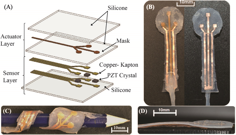
Figure 1. The construction of the SPA skin with integrated PZT sensors. The schematic of the multi-layer construction of SPA skin (A). The prototype shows three sensor pixels for independent measurement (B). Functional SPA skin prototype on a curvy surface (C). The three 4 mm diameter vibratory actuators generate 0.8–1 mm vertical amplitude range (D).
2.1. Actuator Design
The actuation layer of SPA skin consists of two silicone layers and a masking layer sandwiched in between. The first three layers in Figure 1A constitutes for the SPA layer. The masking layer fabricated using a polypropylene adhesive tape, avoids bonding between these two soft silicone layers which after curing facilitates the passage of air through the masked layer creating desired shape inflation. The shape and design of actuator is determined by laser cutting of the masking tape according to the application. The requirements for the actuator diameter and distributed actuator density are based on the feedback application location on human body (Kaczmarek et al., 1991). From these requirements, we can then decide the average input pressure and the desired output blocked force needed for manipulation from a single actuator. Our prototype demonstrates distributed sensing and vibrotactile feedback capabilities of SPA skin designed for human fingers. We obtained a sufficient blocked force of 0.3 N with a 3–4 mm diameter bubble shaped actuator with 0.4 mm silicone thickness for this application. The distributed actuator single input channel SPA skin is capable of generating tactile feedback for a variety of actuation frequencies ranging from 5 to 100 Hz.
2.2. Sensor Design
Sensors for the SPA skin need to be distributable over an area, thin and flexible to be wearable. For our application, we focused on achieving a high-level of sensitivity as well. Soft material matrix-based sensors are often considered for wearable devices but display high drift and slow response that are not suitable for our goal. Piezoelectric ceramics (PZT) are known to be highly sensitive to normal forces applied and can be embedded into silicone substrates (Acer et al., 2015). A PZT element can measure dynamic forces by converting the applied mechanical stress into electrical voltage. Our sensors have multiple pixels of PZT elements discretely distributed over a surface area in the form of grid. The PZT elements are connected using flexible circuit tracks manufactured by laser cutting the copper-plated kapton (polyamide) material. The construction is then embedded inside silicone material for additional support and electrical insulation as shown in Figure 1A.
The sensors for SPA skin use 2 mm × 2 mm size PZT element sandwiched between flexible copper–kapton circuit track. Initially the copper–kapton sheet is finely engraved with a low power laser to remove the kapton layer and make the copper layer visible for connection with PZT element as shown in Figure 2A. After the engraving process the copper–kapton sheet is cut into the specific shape required to form electrodes. A two-way Z-direction conductive adhesive tape (3M™-9705) is used to bond individual PZT element with the copper–kapton electrodes as shown in Figure 2B. This sensor manufacturing procedure enables both signal conducting electrodes to be placed on top of the other without causing a short circuit. The Kapton layer between the electrodes acts as an electrical insulator as depicted in Figure 2D. This helps to reduce the area required for electronic tracks and also improves the sensor density for distributed sensing. For our prototype design, we manufactured three sensors, evenly distributed on a 6-mm circular periphery to sense both the internal and external interactions with the SPA skin, as shown in Figure 2C.
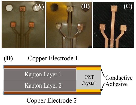
Figure 2. 3-Pixel PZT sensor layer composition. The copper–kapton sheet is engraved using a micro-UV laser to facilitate electrical contact with PZT material (A). Conductive adhesive tape is attached to bond the PZT crystal (B). The same process is repeated for another copper–kapton sheet, and then both electrodes are placed on top of other with PZT crystal sandwiched in between (C). Schematic view of the sensor construction (D).
2.3. Sensor Actuator Integration
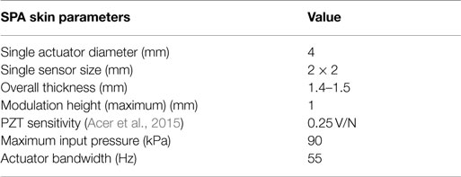
The key challenge for multi-layer-based sensors is their integration in parallel. The integration process is simplified by independently manufacturing the sensors and SPA skin. Additionally, this helps to reduce the failure modes as both sensing and actuation components can be tested before final integration. The layerwise construction of SPA skin and the integrated PZT sensors is depicted in Figure 1A. The sensitivity of vibration feedback is maximized by placing the sensing elements exactly below the bubble-shaped actuator. The flexible circuit tracks are then designed and laser cut, based on the distributed configuration of the sensor elements. The integration process of the PZT sensors into SPA skin starts by spin coating a thin layer of uncured Dragon Skin 30® onto a cured 400 μm thick layer for bonding purpose. A properly connected working sensor is then placed on this uncured silicone. The SPA skin prototype is then aligned with the sensors and placed on the uncured layer. A small weight is placed on this setup to avoid air bubbles forming inside the bonding layer and the assembly is cured at 60°C for 1 h to ensure seamless bonding. Figure 1B shows the final SPA skin prototype with integrated sensors consisting three sensors and three actuators distributed over the soft surface. Using this design procedure, we obtained following parameters for sensor-integrated SPA skin, as shown in Table 1.
3. SPA Skin: Embedded Sensing and Control
The sensorized, tactile SPA skin prototype focuses on two main functionalities; it not only detects vibro-tactile feedback amplitude but also measures external interactive forces. Even with high sensitivity PZT sensors, it is challenging to accurately estimate the dynamical forces on the system as the real world interaction forces the human body experiences are small (in the order of 0.1–3 N) (Kaczmarek et al., 1991). Also, the wearable application requires raw sensor signal to be carried along relatively long wires from application area to the electronics unit, which adds extra capacitance and external signal noise. These issues in combination lower the signal to noise ratio, which requires external amplification and active filtering of noise to improve PZT signal quality.
In this section, we discuss the embedded sensing mechanism for SPA skin to obtain the operational specifications for the embedded PZT elements both mathematically and experimentally. These specifications are then used to design the electronics for the distributed sensing system. This is followed by the design of the control system for augmenting the SPA actuation amplitude with sensor data.
3.1. Embedded Sensing Mechanism
A PZT sensor does not provide a static signal as the piezoelectric effect only occurs when external forces cause a change in the PZT crystal’s physical dimensions. Due to their high sensitivity, PZT sensors are suitable for measuring dynamically changing signals such as vibration or impact force. The sensors produce electrical field, E, proportional to the stress, σ, generated by an external force, Fpiezo, specifically in the normal direction. The transfer function for the generated electrical voltage change can be obtained using the direct piezo electric effect given as E = g33 × σ where, g33 is the piezoelectric voltage coefficient in the normal direction. The relationship in terms of generated open-circuit voltage, V, becomes where t is thickness of PZT and A is the PZT area under stress. For the PZT material (PSI-5H4E), we obtained V = 0.6 × Fpiezo with g33 = 19.0 × 10⁻³ V m/N, t = 0.127 mm, and A = 2 × 2 mm2.
Using the equations (124) and (125) from IEEE (1988) for quasi-static applications, the unloaded or free piezo sensitivity can be mapped to a clamped piezo sensitivity value through the electro-mechanical coupling factor, k33, as shown in equations (1) and (2).
This translates to,
where, ϵr is relative permittivity of PZT crystal in normal direction.
Although significantly better than silicone-based sensors, PZTs too suffer from non-linearities in the form of hysteresis and creep as piezo electric constant (d33) and dielectric constant (ϵr) changes on application of stress (Damjanovic, 1997; Hall, 2001). In our sensor application, we obtain the maximum stress of 0.75 MPa for 3 N load, which generates the maximum electric field of 0.0145 kV/mm. These values are much lower than the nominal stress (5 MPa) or electric field (0.5 kV/mm) to observe significant hysteresis as presented in (Damjanovic, 1997; Hall, 2001) for PZT-5H (soft PZT). Also, the dielectric constant and piezo electric constants do not change for applied stress of <1 MPa (Zhao and Zhang, 1996). Furthermore, the material dynamic equation for the silicone-embedded PZT sensor is complex to model due to the hyper elastic properties of silicone, which are more dominant than PZT non-linearities. The transfer function is also modulated by the thickness of the silicone layer (Acer et al., 2015).
We experimentally obtained sensitivity value of 0.24–0.26 V/N for a silicone thickness of 0.4 mm from the graph shown in Figure 3A. The sensor response is linearly dependent upon the impact force. These results are comparable with the results in equation (2) and results obtained in Acer et al. (2015) for the characterization of silicone-embedded PZT sensors.
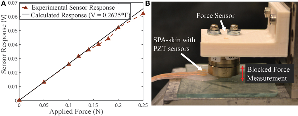
Figure 3. Silicone-embedded PZT sensor characteristics. Silicone-integrated PZT sensor response (A) obtained for a 10 Hz stepped force input of different amplitude. Test setup with Nano-17 force sensor used for the PZT sensor and soft actuator characterization (B). The Nano-17 sensor position can be adjusted precisely in the z-direction to accommodate the exact thickness of SPA skin.
3.1.1. Integrated system response
The system response of the 4-mm diameter actuation chamber is measured by applying a 10-Hz on–off input signal to the actuator placed under a Nano-17 force sensor and a flat plate. The distance between force sensor and the flat plate is same as the actuator thickness (1.4 mm). Figure 4 shows the actual blocked force recorded for actuator inflation and deflation. The rise time for the actuator’s dynamic response is obtained by first order dynamic system model approximation fitted using the input–output data (Figure 4A). The presented model has the first-order transfer function 356/(jω + 356), which subsequently yields time constant of 28 ms and actuator bandwidth of 356/(2π) = 56 Hz, as plotted in Figure 4B. When a similar system response is recorded using the PZT sensor placed just below the actuator, we obtain a bandwidth of 40 Hz (Figure 4B) instead of the modeled bandwidth of 56 Hz. This discrepancy is due to the low pass filtering effect introduced by the charge amplification stage in the sensor readings. This amplifier has a cut-off frequency of 86 Hz as discussed in the following section. This limits the overall cut-off frequency to 44 Hz as shown by brown dotted line in Figure 4B, which is very close to the actual cut-off frequency observed using PZT sensors.
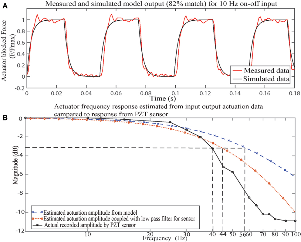
Figure 4. SPA skin system vibration-control response. SPA skin actuated at 10 Hz to experimentally obtain the rise-time and bandwidth of the actuator. First order dynamical system model’s output compared to experimentally recorded blocked force output at 10 Hz (A). The rise time of 0.028 ms is obtained with 82% model fit. The corresponding bandwidth of 56 Hz for first order transfer function compared with actual recorded bandwidth of 40 Hz using PZT sensors (B). Low pass filtering at 86 Hz in PZT signal amplification coupled with estimated actuator bandwidth lowers the measured bandwidth to 44 Hz from 56 Hz.
3.2. Distributed Sensing
Distributed sensing is a critical aspect in the design of any wearable platform. A dense grid of distributed-sensing elements makes wearable systems interactive and adaptive toward changes in the physical environment. Furthermore, the sensing layer faces critical challenges including the signal quality in noisy interactions, sensor density over a specific area, bio-compatibility, flexibility, and weight constraints. The PZT sensors are specifically developed for distributed sensing. The novelty in our design includes customizability, high density, parallel information gathering and the possibility of active feedback control. The system design is optimized for distributed sensing by moving most of the signal processing inside a compact digital platform. The block diagram in Figure 5 represents the system design for signal acquisition, processing, evaluation, and finally active control of the desired vibrotactile feedback. The PZT signal is processed accordingly to obtain a reliable peak value for the periodic force exerted by the soft actuator. A peak detection algorithm and notch filter are developed for decoupling the line noise, external interaction signal, and SPA-generated interaction signal for improving the signal quality to facilitate feedback control as follows.
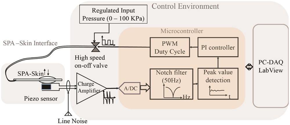
Figure 5. Block diagram for SPA skin interfaced with the control environment for a single sensor and actuator. The SPA skin interface receives pneumatic input and produces piezo electric output. The control environment performs signal acquisition, amplification, conditioning, control, and output actuation tasks from the raw PZT signal. Microcontroller-based signal processing reduces the circuit area required for multiple sensors, as only a new charge amplifier is added per sensor. The long connecting electrodes from PZT sensor capture external line noise, which gets amplified through charge amplifier block.
3.2.1. Input Force Sensing by a Analog Charge Amplification and Filtering
The SPA skin is ultimately aimed for measuring and analyzing the various interaction forces with the human skin in everyday life. The distributed PZT sensors are sensitive to dynamic forces producing electric charge spikes proportional to the impact force. The actual interaction forces exerted on PZT crystals are proportional to the peak value of the electrical voltage generated. Therefore, for the detection of the impact force, the microcontroller tracks the maximum value of the PZT signal over a complete on-period for the given PWM frequency, f. This peak value is then updated for the next timing cycle, and thus, the system has a delay of 1/f. Also, the forces exerted in this case are expected to be <3 N/finger (Lambercy et al., 2007). The maximum force exerted by the SPA skin upon actuation is around 0.3 N at actuation pressure of 70 kPa. This produces a raw signal peak of 75 mV with the given sensitivity of 0.25 V/N. The signal has low amplitude and is susceptible to electrical loading if driven directly through low impedance circuit. Therefore, a charge amplifier was designed to act both as a buffer circuit and an amplification stage. The PZT signal is amplified and low pass filtered by the charge amplifier. The amplification factor of 3.9 allows a maximum external force detection up to 10 N with a 2.5 V amplifier output swing and a cut off frequency of 86 Hz allows filtering of high frequency noise harmonics. The conditioned signal is then converted into 10-bit digital signal sampled at 1000 Hz for further analysis and recording as shown in Figure 5. Every PZT sensor requires an analog signal amplification before it can be connected to a low impedance A/D converter pin.
3.2.2. Distributed Sensor Noise Cancelation
A high density of distributed sensing elements comes with an added cost of increased electrical track and wire lengths. These long wires act like an antenna and capture the noise from a variety of AC sources in their environment. Low amplitude PZT signal and noise signal are amplified to the same extent through charge amplifier; to mitigate this effect, we used a second order digital notch filter. Figures 6A,B show the components of 50 Hz noise compared to the PZT sensor generated values at 20 and 70 Hz respectively. A separate second-order digital Butterworth filter is implemented for every sensor to remove the 50-Hz signal component. The dashed lines in Figures 6A,B show the signal spectrum after removal of the AC noise and display clear acquisition of the repeated actuator signal. A digital filter is preferred an analog filter as it reduces the size of the physical system considering one physical filter would be required for each sensor. Furthermore, the digital filter is equally reliable due to a relatively high sampling frequency of 1 kHz.
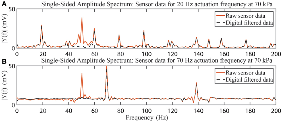
Figure 6. Filtering effect of second-order notch filter on PZT signal quality. The raw sensor data are acquired for vibrotactile actuation of 20 Hz (A) and 70 Hz (B). The raw sensor data contain large component of line noise, which is suppressed using the second digital notch filter.
3.3. SPA Skin Control
The SPA skin consists of an array of actuators, which produce the desired inflation for a specific pneumatic input pressure. Any hardware actuator, including DC motors, pneumatic regulators, and pressure valves, requires a feedback mechanism to accurately control the actuation. However, we rarely observe this in vibratory actuators (Precision_Microdrives_Ltd, 2015). When we require closed-loop control, it is not feasible to rely on human sensory perception for actuator tuning or comparison as sensory perception varies drastically from one person to another. The integration of sensing elements in SPA skin provides the necessary feedback to allow for closed-loop control of the vibration amplitude. In this section, we evaluate the soft actuator’s dynamics and the response of the integrated PZT sensor to determine the operational bandwidth of SPA skin. This is followed by the design of a feedback controller to accurately control the vibrotactile stimulation with small disturbances.
3.3.1. Operational Bandwidth of SPA Skin
Feedback through the physical interface is dictated by the level of the input frequency. Therefore, the system response of the SPA skin was investigated for a variety of actuation frequencies to determine the actual operational bandwidth and effectiveness of the vibrotactile feedback. The signal conditioning circuit has a cut-off frequency of 86 Hz, so we recorded data for the actuator’s response between 10 and 90 Hz. The Figure 7 shows the raw data recordings for a variety of frequencies at a constant input pressure. The actuator bandwidth obtained for the current setup with a tube length of 50 cm, an inlet diameter of 1 mm and an actuation chamber of 4 mm diameter is approximately 35 Hz. Ideally, this should limit the practical maximum control bandwidth for the vibrotactile feedback to 40 Hz. Human finger skin has sensitivity to vibrotactile stimuli of even lower amplitudes and forces (Mortimer et al., 2007). We experimentally obtained perceivable stimulation and measurable variation in the sensor reading from an input pressure of 19 kPa onward for the SPA skin setup. The response of this minimum perceivable signal is shown in Figure 7 together with the frequency response at nominal input pressure (70 kPa). We observe that even near the cutoff frequency, the amplitude of the nominal input signal is higher than the minimum perceivable amplitude for tactile sensation. This extends the operational bandwidth of the SPA actuator from 40 to 90 Hz.
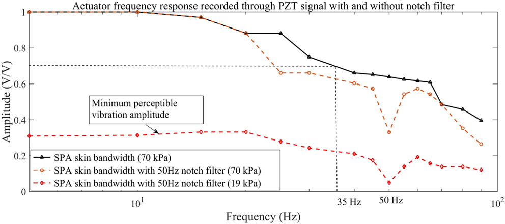
Figure 7. Frequency response of sensor integrated SPA skin as measured by the control environment. The SPA skin produces measurable vibrations from 19 kPa onward of the regulator pressure. The SPA skin amplitude response at 70 kPa is always above the minimum perceptible amplitude for the frequency range of 10–90 Hz.
3.3.2. Controller for Augmented Vibratory Pneumatic Actuation
As the SPA skin is composed of hyper-elastic material, the relationship between the input pressure and the output amplitude of the actuator is non-linear by nature. Furthermore, minute fabrication defects can cause variations in the properties of the SPA skin. This makes open loop control of the actuation amplitude impractical. We therefore present a closed-loop feedback system for accurate vibrotactile stimulation.
We have approximate model fit for the sensor-actuator system with first order dynamics as discussed in Section 3.1. Assuming this linear range of operation PI(D) controller is implemented to demonstrate the active closed-loop feedback capability. The derivative term is zero to avoid noise amplification on discrete update of input signal (detected peak-value signal). The actuation amplitude is a function of the average pressure inside the inflated chamber. As the pressure regulator used in the setup has a time constant of 1.5 s, it can not be used for high-speed control of the input pressure. Instead, a high-speed on-off valve is added and its duty cycle is used as the control parameter for a desired average input pressure. The relationship between the percentage duty cycle and the maximum average pressure inside the actuation chamber is linear, independent of the frequency of actuation. The slope of this relationship is determined by the input pressure from the regulator. As previously shown in Figure 3 the sensor response is linearly proportional to the change is the normal applied force. Therefore, the sensor signal can be used to actively compensate for the deviation from the set point (SP) value. The PI control law for this system is as follows:
In the digital domain for sampling time, Ts, equation (4) becomes,
and the corresponding difference equation for the controller is:
where, K1 = KP + KITs and K2 = −KP.
The PI gains are tuned to obtain a stable controller response over a range of operating frequencies between 10 and 90 Hz. For the current SPA skin design, the set point value for a required blocked force ranges from 0 to 0.3 N, which translates to sensor readings of 0–300 mV. The experimental results for this closed-loop system are presented in Section 4 and demonstrate steady response for a given set point.
4. Closed-Loop Control of the SPA Skin Prototype with Internal and External Inputs
In the first subsection, we evaluate the controller performance for desired step input for the input signal from SPA skin’s actuation at two different frequencies. The second subsection demonstrates the capability of the PZT sensors to detect external interaction forces and differentiate them from the internal vibrotactile actuation.
4.1. Closed-Loop Control of the Vibratory Motors of SPA Skin at 15 and 70 Hz
The haptic feedback research has yet to focus on controlling the vibratory actuation. Not only there is a lack of measurable setup in both actuator and sensor but also it has been more interesting to investigate on the vibrational effect upon the contact. In fact, it has been the human skin that served as the feedback mechanism in the loop. However, to understand and perceive the quantifiable effects of vibrations, we need to close-loop control the actuator. Because we already have the PZT sensors embedded within the actuator layer, we can use these PZT sensors to serve the double duty to control the actuation as well. To do this, we developed a PI-based closed-loop control to achieve active control over the vibration amplitude and consequently control the level of the vibrotactile feedback that will be perceived by the user. The peak value detected from PZT sensor signal during each on-off cycle of the output actuation is used as the input control signal. The digital controller takes control action as soon as a new peak value is available. The controller gains K1 and K2 [in equation (6)] are tuned in order to obtain a stable performance over a range of actuation frequencies without gain re-scheduling. The test results in Figure 8 show controller response for a set point step at a relatively lower vibration frequency of 15 Hz and at a relatively higher vibration frequency of 70 Hz. The controller output is used to drive the PWM duty cycle value of the on-off control valve, which in turn change the average pressure inside actuation chamber. It can also be observed from Figure 8 that in both tests the controller settles in <0.5 s. During our experiment, the controller minimized the disturbances originated from minor manufacturing defects, variation in inlet tube length, and external loading during actuator placement on human body.
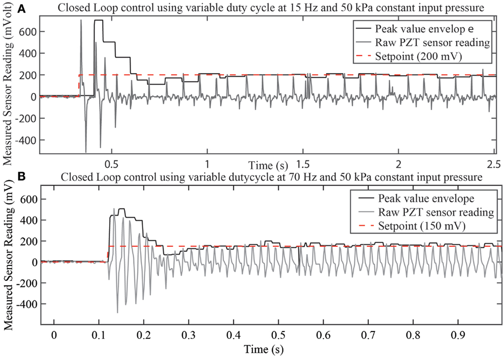
Figure 8. Closed-loop control results for the PI-controller. The SPA skin is actuated at 15 Hz (A) and 70 Hz (B) at a constant regulator pressure of 50 kPa to validate the controller performance over range of actuation frequencies. The peak value envelope signal derived from the raw PZT sensor reading acts as a control signal to generate the desired duty cycle for the pneumatic valve.
4.2. Detection of External Interaction Forces
The sensing capability of SPA skin is not only limited to vibrotactile actuation amplitude but can also further be used to detect external interaction forces. Currently, there are very few haptic devices that can embed contact force sensors, which allows monitoring and controlling of the vibration motors in a closed loop. Therefore, the closed-loop controllable SPA skin is even more suitable for the wearable application environments where it not only provides vibrotactile feedback but also measures the external forces the wearable body faces. As we only have a single sensor array for the contact input, we developed decoupling algorithm to process the acquired PZT signal. We categorize the signal into two components such as (A) SPA skin actuation and (B) external interaction forces. External interactions are typically of low frequencies (<20 Hz) as observed from Figure 9A. Therefore, we excited SPA skin at a higher frequency (65 Hz) than frequency range of external disturbance signal. The peak value detection algorithm uses the knowledge of actuation frequency to detect the PZT signal envelope. This detected envelope selectively suppresses the high-frequency component due SPA skin actuation and upon low-pass filtering at 25 Hz, the component of the SPA skin actuation frequency is completely decoupled. The frequency spectrum of the peak value envelop signal (Figure 9A) shows complete suppression of vibration frequency at 65 Hz and preservation of disturbance signal. This technique is similar to the diode detector or the square law detection algorithm used in recovering the amplitude modulated (AM) signal (Carlson, 1986).
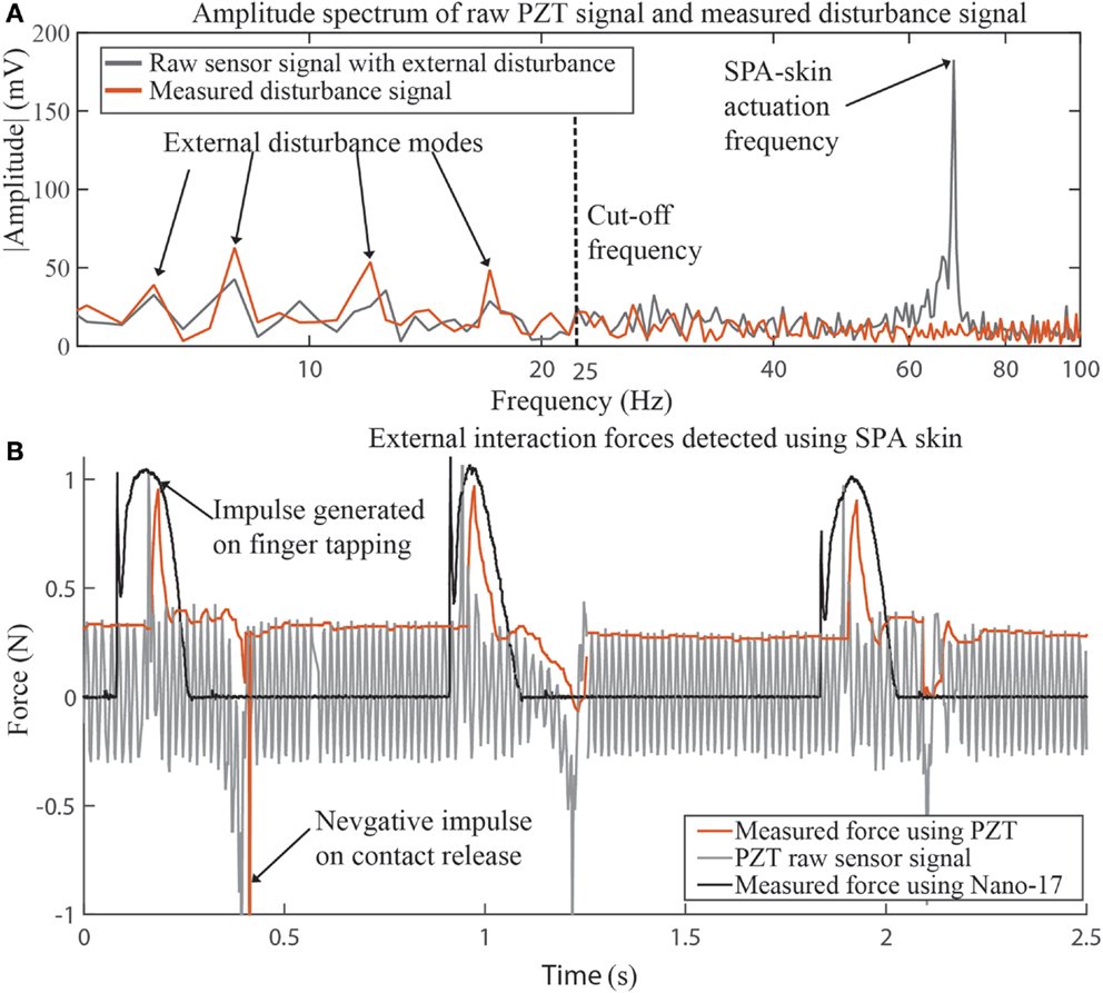
Figure 9. SPA skin external signal detection. Frequency domain representation (A) of raw sensor signal and filtered peak value signal clearly demonstrates the capability to filter actuator vibrations and preserve disturbance signal. The external physical disturbances have interaction frequencies <20 Hz. Detection of external interaction due to finger tapping on previously actuated SPA skin at 65 Hz (B). The force sensor data and filtered PZT data in (B) read comparable interaction force on positive impact.
The SPA skin vibrating at 65 Hz is placed on top of a Nano-17 force sensor to record the external impact force. We tapped on the actuation area multiple times to provide the disturbance input. When finger is tapped on the vibrating SPA skin an impulse is generated as shown in Figure 9B recorded by both the Nano-17 force sensor and the PZT sensors. As PZT sensors are embedded inside the soft silicone structure, they can also sense an impulse in negative direction (Figure 9B) on contact release. The rigid force sensor cannot measure this interaction in the opposite direction. The force sensor measured 1 N impact force, which is the coupled force of vibrotactile actuation and impact. The results obtained using force sensor are comparable with the dynamic interaction forces detected by PZT sensor though this requires initial calibration of the PZT sensor.
5. Conclusion
We introduced a unique, compliant, and distributable actuation system with embedded grid of sensing capabilities. The distributed sensing with high customizability makes the SPA skin more versatile to accommodate multiple configurations for wearable applications. Because of its softness and flexibility, it can cover wide and curvy surfaces for actuation and sensing. Furthermore, the presented SPA skin is both an input and output device that produces a modulating vibrotactile feedback over a range of frequencies. The embedded PZT sensors help SPA skin to precisely control vibration and to detect external forces and contacts. The novel method of sensor manufacturing allows placing a grid of sensor electrodes over a surface. However, these capabilities are limited by the tethered wires that create a noisy environment. Digital filtering becomes necessary as the sensed signal amplitude is comparable to the line noise captured by the long running wires acting as an antenna.
We developed an algorithm to decouple the internal and external interaction signals to maximize the detectable range of forces including feedback control of the vibratory actuators. The peak value generated on sensor by step actuation of the SPA contains the information about the blocked force exerted by the single actuation cell on the sensor. The filtered sensor data is therefore recorded over a complete PWM on-time to measure the peak value. This value is used by the closed-loop controller to take the necessary control action. The detected peak value is updated every period of the actuation frequency, limiting the control bandwidth to the frequency of SPA actuation. For the presented prototype, we concentrated on implementation of the controller and external signal detection for a single sensor and actuator. The present hardware and micro-controller platform can simultaneously detect peak values up to 16 sensors and control 16 actuators using independent feedback controllers at 1 kHz. The capabilities can be further extended based on the distributed sensing requirements.
In near future, more experiments will be carried out with variety of sensor and actuator sizes to evaluate the dynamic model and over all transfer function of the sensor integrated SPA skin. Better techniques to minimize the noise through optimal shielding and robust filtering will be investigated. Efforts are being made to integrate the sensor-embedded SPA skin as a plug and play wearable vibrotactile component for a virtual reality system and a feedback mechanism for a rehabilitation device.
Conflict of Interest Statement
The authors declare that the research was conducted in the absence of any commercial or financial relationships that could be construed as a potential conflict of interest.
Funding
This work is funded by the Swiss National Centre of Competence in Research (NCCR) in Robotics.
References
Acer, M., Salerno, M., Agbeviade, K., and Paik, J. (2015). Development and characterization of silicone embedded distributed piezoelectric sensors for contact detection. Smart Mater. Struct. 24, 075030. doi:10.1088/0964-1726/24/7/075030
Alahakone, A., and Senanayake, S. (2009). “Vibrotactile feedback systems: current trends in rehabilitation, sports and information display,” in IEEE/ASME International Conference on Advanced Intelligent Mechatronics (AIM 2009) (Singapore: IEEE), 1148–1153.
Asamura, N., Shinohara, T., Tojo, Y., and Shinoda, H. (2001). “Necessary spatial resolution for realistic tactile feeling display,” in ICRA (Seol: IEEE), 1851–1856.
Carlson, A. B. (1986). Communication Systems: An Introduction to Signals and Noise in Electrical Communication, 2nd Edn. New York: McGraw-Hill Education.
Carmeli, E., Peleg, S., Bartur, G., Elbo, E., and Vatine, J.-J. (2011). Handtutortm enhanced hand rehabilitation after stroke a pilot study. Physiother. Res. Int. 16, 191–200. doi:10.1002/pri.485
Choi, S., and Kuchenbecker, K. (2013). Vibrotactile display: pe0072ception, technology, and applications. Proc. IEEE 101, 2093–2104. doi:10.1109/JPROC.2012.2221071
Damjanovic, D. (1997). Stress and frequency dependence of the direct piezoelectric effect in ferroelectric ceramics. J. Appl. Phys. 82, 1788–1797. doi:10.1063/1.365981
Frediani, G., Mazzei, D., De Rossi, D. E., and Carpi, F. (2014). Wearable wireless tactile display for virtual interactions with soft bodies. Front. Bioeng. Biotechnol. 2:31. doi:10.3389/fbioe.2014.00031
Gerratt, A. P., Michaud, H. O., and Lacour, S. P. (2015). Elastomeric electronic skin for prosthetic tactile sensation. Adv. Funct. Mater. 25, 2287–2295. doi:10.1002/adfm.201404365
Hall, D. (2001). Review nonlinearity in piezoelectric ceramics. J. Sci. Mater. 36, 4575–4601. doi:10.1023/A:1012916408297
Hirose, M., Hirota, K., Ogi, T., Yano, H., Kakehi, N., Saito, M., et al. (2001). “Hapticgear: the development of a wearable force display system for immersive projection displays,” in Virtual Reality, 2001. Proceedings IEEE (Yokohama: IEEE), 123–129.
IEEE. (1988). IEEE standard on piezoelectricity. ANSI/IEEE Std 176-1987. doi:10.1109/IEEESTD.1988.79638
Kaczmarek, K., Webster, J. G., Bach-y Rita, P., and Tompkins, W. J. (1991). Electrotactile and vibrotactile displays for sensory substitution systems. IEEE Trans. Biomed. Eng. 38, 1–16. doi:10.1109/10.68204
Kapur, P., Premakumar, S., Jax, S., Buxbaum, L., Dawson, A., and Kuchenbecker, K. (2009). “Vibrotactile feedback system for intuitive upper-limb rehabilitation,” in World Haptics 2009 – Third Joint EuroHaptics conference, 2009 and Symposium on Haptic Interfaces for Virtual Environment and Teleoperator Systems (Salt Lake City, UT: IEEE), 621–622.
Koo, I. M., Jung, K., Koo, J. C., Nam, J.-D., Lee, Y. K., and Choi, H. R. (2008). Development of soft-actuator-based wearable tactile display. IEEE Trans. Robot. 24, 549–558. doi:10.1109/TRO.2008.921561
Lambercy, O., Dovat, L., Gassert, R., Burdet, E., Teo, C. L., and Milner, T. (2007). A haptic knob for rehabilitation of hand function. IEEE Trans. Neural Syst. Rehabil. Eng. 15, 356–366. doi:10.1109/TNSRE.2007.903913
Lindeman, R. W., Yanagida, Y., Noma, H., and Hosaka, K. (2006). Wearable vibrotactile systems for virtual contact and information display. Virtual Real. 9, 203–213. doi:10.1007/s10055-005-0010-6
Maciejasz, P., Eschweiler, J., Gerlach-Hahn, K., Jansen-Troy, A., and Leonhardt, S. (2014). A survey on robotic devices for upper limb rehabilitation. J. Neuroeng. Rehabil. 11, 3. doi:10.1186/1743-0003-11-3
Maiolino, P., Galantini, F., Mastrogiovanni, F., Gallone, G., Cannata, G., and Carpi, F. (2015). Soft dielectrics for capacitive sensing in robot skins: performance of different elastomer types. Sens. Actuators A Phys. 226, 37–47. doi:10.1016/j.sna.2015.02.010
Mortimer, B. J., Zets, G. A., and Cholewiak, R. W. (2007). Vibrotactile transduction and transducers. J. Acoust. Soc. Am. 121, 2970–2977. doi:10.1121/1.2715669
Precision_Microdrives_Ltd. (2015). Vibration Motors [Online]. Available at: https://catalog.precisionmicrodrives.com/order-parts
Rosset, S., OBrien, B. M., Gisby, T., Xu, D., Shea, H. R., and Anderson, I. A. (2013). Self-sensing dielectric elastomer actuators in closed-loop operation. Smart Mater. Struct. 22, 104018. doi:10.1088/0964-1726/22/10/104018
Shahoian, E., Martin, K., Schena, B., and Moore, D. (2004). Vibrotactile haptic feedback devices. US Patent 6,693,622.
Smooth_On_Inc. (2015). Dragon Skin 30 [Online]. Available at: http://www.smooth-on.com/tb/files/DRAGON_SKIN_SERIES_TB.pdf
Suh, C., Margarit, J., Song, Y. S., and Paik, J. (2014). “Soft pneumatic actuator skin with embedded sensors,” in 2014 IEEE/RSJ International Conference on Intelligent Robots and Systems (IROS 2014) (Chicago, IL: IEEE), 2783–2788.
Takahashi, C. D., Der-Yeghiaian, L., Le, V., Motiwala, R. R., and Cramer, S. C. (2008). Robot-based hand motor therapy after stroke. Brain 131, 425–437. doi:10.1093/brain/awm311
Viau, A., Feldman, A. G., McFadyen, B. J., and Levin, M. F. (2004). Journal of neuroengineering and rehabilitation. J. Neuroeng. Rehabil. 1, 11. doi:10.1186/1743-0003-1-11
Wall, C. III (2010). Application of vibrotactile feedback of body motion to improve rehabilitation in individuals with imbalance. J. Neurol. Phys. Ther. 34, 98. doi:10.1097/NPT.0b013e3181dde6f0
Xu, S., Zhang, Y., Jia, L., Mathewson, K. E., Jang, K.-I., Kim, J., et al. (2014). Soft microfluidic assemblies of sensors, circuits, and radios for the skin. Science 344, 70–74. doi:10.1126/science.1250169
Keywords: wearable technology, soft skin, smart actuators, soft sensor, soft actuator, vibrotactile feedback
Citation: Sonar HA and Paik J (2016) Soft Pneumatic Actuator Skin with Piezoelectric Sensors for Vibrotactile Feedback. Front. Robot. AI 2:38. doi: 10.3389/frobt.2015.00038
Received: 20 October 2015; Accepted: 17 December 2015;
Published: 11 January 2016
Edited by:
Carlo Menon, Simon Fraser University, CanadaReviewed by:
Gursel Alici, University of Wollongong, AustraliaRobert Shepherd, Cornell University, USA
Copyright: © 2016 Sonar and Paik. This is an open-access article distributed under the terms of the Creative Commons Attribution License (CC BY). The use, distribution or reproduction in other forums is permitted, provided the original author(s) or licensor are credited and that the original publication in this journal is cited, in accordance with accepted academic practice. No use, distribution or reproduction is permitted which does not comply with these terms.
*Correspondence: Jamie Paik, amFtaWUucGFpa0BlcGZsLmNo
†Harshal Arun Sonar and Jamie Paik have contributed equally to this work.
 Harshal Arun Sonar
 Jamie Paik