 Lily Kamat
 Priscilla Delgado
 Anjana Dissanayaka
 David R. Myers
94% of researchers rate our articles as excellent or good
Learn more about the work of our research integrity team to safeguard the quality of each article we publish.
Find out more
ORIGINAL RESEARCH article
Front. Lab Chip Technol., 08 July 2024
Sec. Micro- and Nano-fabrication
Volume 3 - 2024 | https://doi.org/10.3389/frlct.2024.1365774
This article is part of the Research TopicCelebrating 1 Year of Frontiers in Lab on a Chip TechnologiesView all 4 articles
Introduction: Self-coalescing microfluidic devices represent an exciting opportunity for leveraging viscous dominated flow phenomena to reconstitute a series of reagents with a single sample infusion. In a self-coalescing microfluidic device, spatially separated dried reagents are reconstituted using a single infusion. Due to the unique device geometry, the reagents remain spatially separated after infusion. As such, self-coalescing microfluidic devices have the potential to simplify point-of-care testing by simultaneously performing multiple colorimetric tests in one device. The current versions of these devices use standard, more costly microfabrication processes and are too small to be easily read by eye.
Methods: Here, we created a low cost and scaled up version of a self-coalescing microfluidic device by using laser-cut-roll-based silicone tape. In addition to eliminating the need for cleanrooms, our approach simplifies the integration of assay reagents since they can be spotted onto a coverslip and covered with the tape microfluidic device. We empirically optimized our device, finding that flow rate significantly influenced the formation of self-coalescence as well as proper reagent reconstitution.
Results and Discussion: When flow rates were too slow or fast, reagents would streak, leading to inadvertent mixing between different spatial locations. Our studies further revealed that geometry had a stronger influence on device operation in low-flow conditions. Our final optimized device exhibited a 100% success rate, demonstrated through self-coalescence with no reagent streaking at 100 μL/min, which enabled the isotropic diffusion of reagents. Furthermore, the spots are spatially separated and large enough to be visualized by the naked eye and captured by a smartphone camera for downstream analysis. Taken together, our innovative device leverages the advantages of sticker microfluidics and low-cost manufacturing methods to offer standalone functionality. This approach has the potential to significantly impact point-of-care diagnostics, particularly in resource-limited regions. By enabling multiplexed diagnostic assays through our novel technology, we aim to provide accessible and affordable healthcare solutions.
Microfluidic devices offer enormous potential for point-of-care (POC) assays as they are self-contained and small, conserving both reagents and patient samples. Ideally, one simply places dried reagents within the device and infuses the sample liquid over the reagents to reconstitute them. Unfortunately, this can be challenging as reagents tend to accumulate at the liquid front, thereby moving and dispersing away from where they were initially placed. Moreover, this phenomenon makes it nearly impossible to add more adjacent to dried reagent spots, such as other assays or appropriate biochemical controls, since the passing fluid front will smear these various reagents. To deal with the challenge of performing multiple assays on a single microfluidic, different strategies can be employed. In the simplest case, a single microfluidic structure is used to contain each assay, although this scales poorly and necessitates multiple infusions. More advanced solutions rely on valves (Keating et al., 2016). However, implementing these valves in POC settings can be difficult due to the expense and complexity of the design and fabrication processes and/or ancillary required equipment to actuate the valves (Unger et al., 2000; Sesen and Rowlands, 2021).
Self-coalescing microfluidic devices offer a clever solution to this problem and have been used previously to run multiplexed diagnostic assays with a single infusion of a sample (Hemmig et al., 2020; Salva et al., 2020; Rocca et al., 2021; Gervais et al., 2022). The key feature enabling self-coalescence is a capillary pinning line (CPL) (Battat et al., 2022), which is essentially a trench in the device that acts as a Laplace pressure barrier. Fluid fills around one side of this barrier, and then, when that side of the barrier has filled, the fluid folds onto itself and flushes over the trench CPL. As the fluid flows onto itself, it experiences a rapid flow over the CPL and then very quickly stops moving, allowing for the controlled reconstitution of reagents. Overall, this unique flow pattern allows for neighboring reactions without the need of physical compartmentalization, enabling users to integrate multiple assays into a single channel microfluidic chip. While very clever, challenges with existing self-coalescing microfluidic devices include the intensive and expensive traditional manufacturing processes and the very small size of the devices—typically within the range of micrometers. While the small size saves reagents and patient samples, it requires the use of equipment such as an inkjet spotter, a piezoelectric pipette, and microtiter plate reader (Gökçe et al., 2019). As such, these challenges restrict the device to high-resource settings with specially trained personnel.
The sequential delivery of reagents or solutions offers many benefits to microfluidic device systems in terms of automation of assays with little to no intervention required from the user (Olanrewaju et al., 2016; Yafia et al., 2022). This automation reduces the incidence of human error and creates an overall simpler system that easily translates from the lab to the clinic. Through the use of sequences, the same sample can be used to run multiple tests, which is ideal for reducing variability from the need to run multiple individual tests for a similar sample. Paper-based microfluidic devices offer a low-cost platform that is capable of sequential flow (Lutz et al., 2011), but the inherent characteristics of fluid flow through a paper-based microfluidic device does not offer as much control over the rate of fluid flow. The use of transparent film sheets, such as roll-based silicone, allows for direct modulation of the rate of fluid flow—limited for the paper-based devices—for each intended application. Utilizing transparent film sheets also maintains low costs. Self-coalescing flow offers an alternative strategy that can also enable the sequential reconstitution of dried reagents if desired. Similar flow profiles have been applied to create microfluidic devices such as chips for nucleic acid hybridization (Salva et al., 2020) and ELISA-on-a-chip (Parandakh et al., 2023). Self-coalescing fluid flow naturally lends itself well to the sequential reconstitution of dried reagents that would be necessary for automating assays in microfluidic devices.
“Sticker” microfluidic devices have been used as electrochemical biosensors (Khashayar et al., 2017) and rapid bilirubin sensors (Tan et al., 2020) and have been employed for tumor metastasis studies (Zhao et al., 2018) and long-term bacterial culture assays (Kong et al., 2019). This double-sided roll-based adhesive is biocompatible, can withstand many electrical, thermal, and chemical processes (Nath et al., 2010), does not necessarily need additional chemical plasma, heat, or chemical treatments, and is easily scalable to larger millimeter-sized channels (Patko et al., 2014). Sticker microfluidic devices offer a low-cost alternative method for creating devices that still leverage microscale phenomena (Zamora et al., 2017; Lai et al., 2019) and do not require a cleanroom (Kim et al., 2009). These sticker devices are made from combinations of double-sided roll-based adhesives with various materials, such as silicon, glass, and polydimethylsiloxane (PDMS). They can be designed, laser- (or craft-) cut, and assembled within an hour (Gerber et al., 2015). We previously published regarding a multilayer dry-film mixing sticker that can be retrofitted to existing microfluidic devices and had comparable function to its traditionally fabricated counterpart (Delgado et al., 2022). With simple instructions, sticker microfluidic devices can be easily fabricated by untrained individuals (Ren et al., 2019), which can thus increase the accessibility of microfluidic device use in fields outside of engineering and as POC use in developing regions of the world. For those reasons, the use of tape microfluidic devices presents a unique opportunity to create complex microfluidic devices in a simple, low-cost manner, even by individuals who are not experts in the field.
Therefore, we sought to create a self-coalescing sticker microfluidic device that is rapid, affordable, and accessible (Figure 1A). To that end, we present our highly effective (Figure 1B) self-coalescing tape microfluidic device that is easy to manufacture, assembled within 10 min, costs less than $2.20 USD (Table 1), and can be integrated with a diagnostic assay. Our simplified laser cutting manufacturing process that begins with double-sided roll-based adhesive and PDMS eliminates the need for a clean room and complex lithography procedures. By scaling up the original design (Gökçe et al., 2019), reagents can be spotted with a pipette if desired, and no specialized equipment (optical plate reader) is needed to analyze the results. Figure 1C compares our device with a mock-up of the 7 mm device presented by Gökçe et al. (2019). The large reaction spots are easily detectible by the naked eye, making them conducive to capture with a smartphone for further downstream analysis of the assay results (Figure 1D).This in turn moves self-coalescing microfluidic devices towards being completely standalone. Like prior self-coalescing microfluidic devices, our device avoids the reagent concentration in the fluid front that occurs with traditional non-self-coalescing microfluidic devices (Figure 2A). Our innovative device has the capability to revolutionize POC diagnostic technologies with its ability to run a multiplexed diagnostic assay with one patient sample (Figure 2B). In addition, we believe that the accessibility of our technology will especially have an impact in low- and middle-income regions of the world that have access to fewer specialized resources needed for traditional microfabrication.
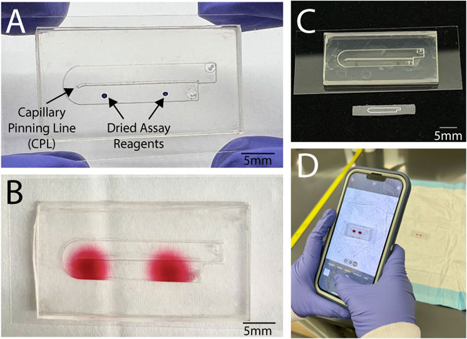
Figure 1. We present a low-cost simplified self-coalescing microfluidic device. (A) The device consists of a single channel layer on top of a layer with a capillary pinning line to aid with self-coalescing flow. A single sample is loaded into the microfluidic device to (B) reconstitute the assay reagents to form two separate reaction spots. (C) The microfluidic device was a scaled-up design using double-sided roll-based silicone tape from an original self-coalescing microfluidic device (depicted below our original design, outlined on a silicon wafer) that used traditional fabrication methods. (D) The device reaction spots are large enough to be easily detected visually and captured through smartphone for further analysis without the need for any plate readers.
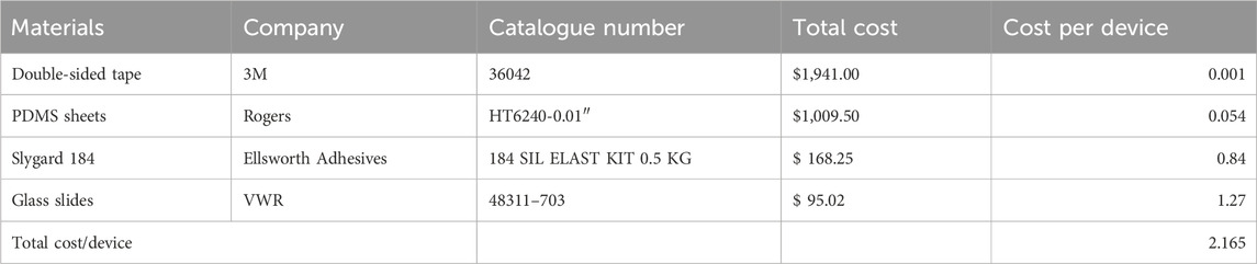
Table 1. Cost analysis for the fabrication of one device.

Figure 2. Self-coalescing flow presents ease of use with one fluidic sample by being able to run multiple reactions. In (A), a microfluidic device without a capillary pinning line where the fluid flows through one serpentine channel, the reagent spots collect at the fluid front. When the (B) microfluidic device has a capillary pinning line on the floor of the microfluidic channel, the fluid is able to reach the end of the channel before folding over itself to create two separate reaction spots with the spotted reagents.
The traditional self-coalescing design was scaled up, extending from a 15 mm length to 25.4 mm, while its width expanded from 0.5 mm to 6.1 mm (Gökçe et al., 2019). This new design was then drawn using AutoCAD software. Before laser cutting, 0.13 mm silicone-adhesive roll-based tape (3M 96042) was attached to 250 µm roll-based PDMS (Rogers HT6240-0.01). Manual pressure and a squeegee were used to push out any air bubbles that formed as the layers were attached to each other. The silicone adhesive and PDMS sheet was then laser cut (using Universal Laser Systems VLS 4.60) into the layers depicted in Figure 3A. Laser cutting settings were optimized to reduce the scorching of material. Any large debris from laser cutting was removed with a Kimwipe before each piece was cleaned using scotch tape. In addition to these layers, the device features a PDMS roof created using a 10:1 mixture of Sylgard 184 (Dow Inc.) elastomer base to curing agent. The 10 g PDMS mixture was degassed for 40 min before being poured into a 100 × 15 mm Petri dish and allowed to cure in the 65 °C oven for at least 3–4 h. Once the PDMS was cured, it was cut with an X-acto knife to fit the rectangular dimensions of our device. A 0.70 mm hole punch was used to create inlet and outlet holes in the PDMS roof. The flow test in Figure 2B was created to demonstrate how non-self-coalescing flow occurs. A device was designed on AutoCAD without a CPL (Figure 2A) and assembled using similar methods to the devices with a CPL, as described below.
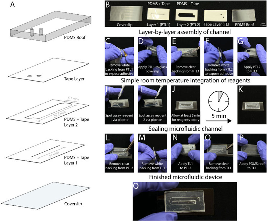
Figure 3. The utilization of laser cut roll-based silicone offers ease of manufacturing for the microfluidic device. (A) The device consists of five layers. These consist of (B) a cover slip, a layer with PDMS and tape that has the CPL (PTL1), a second layer of PDMS and tape (PTL2) that has the microfluidic channel, and tape layer with inlet and outlet holes, and a PDMS roof. The manufacturing is simple as (C) the backing must first be removed from PTL1 and (D) applied to the glass coverslip using minimal physical pressure with a finger. Following this, (E) the clear backing should be removed from PTL1, and (F) PTL2 is then prepared by removing the white backing to expose the adhesive. (G) PTL2 is applied to PTL1 with the same manual pressure. (H) At this stage the device is ready for simple room integration of assay reagents. Due to the scale of the device, the assay reagent can be spotted via pipette and has enough space (I) for two reagent spots. A total 0.4 µL of reagent (J) should be given 5 min to dry into (K) the channel. Once dry, the channel can be sealed by (L) removing the clear backing from PTL2 and preparing TL1 though (M) removing the white backing to expose the adhesive. After (N) applying TL1 to Q18 PTL2 the device is finished by (O) removing the final backing, and (P) applying the PDMS roof to TL1. The result (Q) is a finished microfluidic device.
The sticker microfluidic device was built from the bottom up, starting with a 24 × 50 mm glass coverslip (VWR 48393–241) followed by PDMS + Tape Layer 1 (PTL1), PDMS + Tape Layer 2 (PTL2), Tape Layer (TL1), and the PDMS roof (Figures 3A,B). As shown in Figure 3C, the white backing is firstly removed from PTL1 to expose the adhesive side of the layer. Then, PTL1 is applied to the glass coverslip with light manual pressure (Figure 3D). Next, the clear backing is removed from PTL1 (Figure 3E). After this, the process repeats for PTL2. Firstly, the white backing is removed to expose the adhesive (Figure 3F), then PTL2 is stacked directly on top of PTL1 and lightly pressed onto it (Figure 3G). One of the key features of this manufacturing method allows for assay reagents to be spotted into the channel manually with a pipette (Figures 3H,I). We added 0.40 µL of reagents at ambient temperature, which took at least 5 min to dry (Figure 3J). Figure 3K shows the device with the dried reagents. After the reagent had been added, the clear backing was removed from PTL2 (Figure 3L). Then, the white backing was removed from TL1 (Figure 3M), and TL1 was stacked on top of PTL2 (Figure 3M). Next, the clear backing was removed from TL1 (Figure 3O), and the PDMS roof was gently pressed onto TL1 (Figure 3P). Figure 3Q shows the completed self-coalescing microfluidic device. A range of geometries was empirically tested to determine the optimal device design. This involved adjusting the length of the channel from 23 mm to 27 mm with a constant width of 6.1 mm and the channel width from 3.05–8.1 mm with a constant length of 25.4 mm.
Amaranth at 30 mg/mL (Thermofisher 153030250) and erioglaucine disodium salt (“brilliant blue”) dye at 30 mg/mL (Thermofisher 229730050) suspended in deionized water were spotted and used to mimic reagents within the channel. To aid the visualization of flow, food dye was added to the deionized water for some experiments. The devices featured 2–0.40 µL spots spaced 1 in. apart. Fluidic testing was conducted with deionized water flowed in with a syringe pump or pipette. The devices with DI water infused with a syringe pump (Harvard Apparatus PhD Ultra) had a configuration in which the pump was loaded with a 1 mL syringe connected to Tygon tubing (Cole-Parmer EW-06 419-01) via a blunt needle tip, which connected to the microfluidic device via friction fit tubing. Devices which were infused with a pipette delivered 180 µL of deionized water. All device trials were visually inspected for the success of self-coalescing flow path and were recorded on a smartphone.
The robustness of the self-coalescing tape microfluidic device was systematically investigated by testing various operational conditions. Fabricated devices underwent testing under different flow rates—1 μL/min, 2 μL/min, 10 μL/min, 25 μL/min, 50 μL/min, 100 μL/min, 500 μL/min, and 1,000 μL/min—which were selected to comprehensively assess device performance. Once the flow reached the outlet of the device, the syringe pump was paused to prevent further diffusion of the amaranth spots. Data acquisition involved capturing images post-filling of the device, utilizing a smartphone camera. The smartphone was securely positioned 15 cm above the devices to ensure optimal imaging and data collection. Images were taken using a 12-megapixel smartphone camera system with no optical zoom and were captured under consistent lighting conditions to minimize variations in calculated pixel values. Our observations were centered on the impact of different flow rates on streaking, a dominant parameter for our study objectives. Streaking mitigation was imperative due to its potential interference with the device’s application as a colorimetric assay platform. The avoidance of streaking was necessary to ensure unobstructed and accurate results. The success of the device was characterized on a binary scale of whether the device exhibited the proper self-coalescing flow (Figure 2B). Improper flow within the device was noted, as devices with channels that were not completely filled with fluid had pockets of air, resulting in reagent spots that were not reconstituted with fluid.
We also sought to evaluate the diffusion characteristics of the microfluidic device and gain insights into the dynamic behavior of rehydrated amaranth spots. The experimental setup involved recording an aerial video using a smartphone during the flow. To assess the diffusion capabilities, we ran the devices for a 16-min duration and utilized the Tracker Video Analysis and Modeling Tool, a free video tracking analysis software. Concentration of amaranth spots was quantified by processing measurements of video luma, a representation of brightness calculated using RGB values. These luma values were collected along the channel at the 0, 1, 2, 4, 8, and 16-min timestamps.
Success rates for how the devices worked were indicative of whether self-coalescing fluid flow was exhibited (Figure 4A). Flow rates at 50 μL/min and below exhibited devices with high success rates at 1 and 25 μL/min. However, these devices below 50 μL/min expressed streaking, indicative of suboptimal performance for integration with assay reagents (Figure 4B). At flow rates above 100 μL/min, streaking was absent, affirming robust functionality for assays. The rehydration of reaction spots under these conditions was both adequate and effective. While there was a lack of streaking, the consistency of a device working above 100 μL/min was not consistent. The devices exhibited success rates at 60% and below at 500 μL/min. Lack of success showed indeterminant flow patterns that interfered with reconstitution of the reagents with the deionized water sample. This highlighted the sensitivity of the device to higher flow rates. When adjusting the flowrates and changing one parameter at a time of the channel, the flowrate of 2 μL/min had the most variation in its results (Figures 4C,D), while overall the flowrate of 100 μL/min exhibited higher rates of success in demonstrating self-coalescence (Figures 4E, F).

Figure 4. (A) Success for the device was indicative of self-coalescing flow; however, isotropic diffusion was also an important factor as it allowed the device to be integrated with multiple reagent spots. (B) The speed in which the fluid flows through the microfluidic channel has an effect on the success of self-coalescing flow. While lower flowrate speeds exhibit high success rates, flowrates beneath 50 μL/min exhibit streaking that is not ideal for integration with assays. Flowrates at 500 μL/min and above showed low success rates (<60%) and had improper flow pattern that showed a lack of self-coalescing flow (error bars represent standard errors of the means, n ≥ 4). Upon further characterization of design parameters for the channel dimensions when (C) when holding the width at 6.1 mm at a flowrate of 2 μL/min, there was a lot of variability in the number of devices that had self-coalescing flow. (D) When holding channel length consistently at 25.4 mm, the smaller channel widths did not exhibit as much self-coalescing flow at 2 μL/min. Overall (E) all devices exhibited self-coalescing flow when holding the width at 6.1 mm and a flowrate of 100 μL/min. (F) When adjusting channel width, all devices except for the width of 3.1 mm had self-coalescing flow when held at a length of 25.4 mm and a flowrate of 100 μL/min.
Figure 5 presents the concentration profile of dried amaranth spots over time (0 s, 1 min, 2 min, 4 min, 8 min, 16 min). At the initiation of the experiment (0 min), the peaks representing the dried amaranth spots were modest, evolving in both intensity and breadth by the conclusion of the 16-min period. This observed broadening signifies the successful diffusion of the dried amaranth spots over time.

Figure 5. Assays often require incubation steps to ensure proper reactions. The diffusion of the reaction spots was characterized over 0, 1, 2, 4, 8, and 16 min to show that there would be no cross reactivity between each reaction spot.
Importantly, the peaks remained distinctly separated throughout the 16-min period, affirming the efficacy of our microfluidic device in containing and preserving the individual diffusion zones. This outcome is particularly significant for practical applications where distinct reactions need to occur simultaneously on a single device. Our findings highlight the adaptability of our device to accommodate typical incubation periods (−15 min), a fundamental consideration for real-world applications.
Our investigation was twofold: firstly, to validate the efficacy of our self-coalescing microfluidic device in ensuring the rehydration and controlled diffusion of dried amaranth spots, and secondly to lay the groundwork for its potential application with dried reagents in future work. The self-coalescing tape microfluidic device was designed to host a colorimetric assay reagent, facilitating reactions upon rehydration. Our primary focus was to understand the diffusion behavior of dried amaranth spots prior to accommodating diverse dried reagents in subsequent studies.
Selecting an appropriate flow rate is a key driver of optimal device operation. Tuning the flow rate emerges is a critical factor, as it induces varying effects on streaking (Figure 4). At slower speeds, streaking becomes more pronounced due to rapid rehydration, causing the reagent to be carried along the flow. This presents a problem for assay applications as it would cause reagents to cross react with one another as they are being streaked through the channel. Conversely, excessively high flow speeds result in indeterminate flow profiles, compromising the precise control required for effective streak prevention. Although PDMS deformation at high flow speeds is a concern, there were no discernable deformations observed during testing. Therefore, meticulous consideration and fine-tuning of the flow rate are imperative to optimal device functionality.
Device geometry contributes to the device’s ability to exhibit self-coalescing flow. The length of the channel was less important to the channel’s fluid dynamics, but a narrow width effected the fluid’s flow, and it no longer showed self-coalescing flow. This is consistent with Schwarz–Christoffel mapping in which the two most important factors to exhibit self-coalescing flow are channel width and contact angle.
Ideal loading of the sample into the microfluidic channel would be via pipette to broaden the application of the design to a variety of clinical settings. Preliminary data while attempting to load the device with a pipette rather than a syringe pump also resulted in indeterminant flow. This was due to the high inconsistent variability that pipettes introduced to the sample loading. Throughout these trials, backflow from the operator removing the pipette tip also introduced challenges that reduced the optimal performance of the assay by encouraging unwanted smearing of the reagents. The device design must be further optimized in order to be used with higher flow rates or to be conducive with manual sample loading via pipettes. While the current study prioritized optimization of the device for syringe pump flow to establish a baseline performance with controlled conditions, future studies will investigate refining the device to handle the variability of pipette-induced flow.
While our current investigation focused on the diffusion of dried amaranth spots, our findings lay the foundation for future endeavors incorporating other dried reagents. The success in containing and preserving distinct diffusion zones positions our device as a promising platform for accommodating various dried reagents, broadening its potential applications. Further optimization and expansion of our device could unlock its capacity to simultaneously host multiple dried reagents. This future direction holds substantial promise for enhancing the versatility and utility of our microfluidic device. When scaling it up, empirical designs scaling the length showed that the device would exhibit self-coalescing flow when width was held constant. The only factor that had any effect on the self-coalescing flow pattern was when the width of the device was reduced, making it feasible for the device to easily include more than two reaction spots.
Looking ahead, the envisioned application of our device in diagnostic assays, where dried reagents yield distinct colorimetric results upon rehydration, holds considerable potential. The transparent nature of the polydimethylsiloxane (PDMS) material used in our device opens avenues for clear imaging, and the prospect of employing machine learning (ML) for image analysis could enhance precision and consistency in interpretation.
Moving towards truly point-of-care devices that require minimal equipment for operation is important for the translation of assays from bench to field use. Creating devices with multiple reactions has long been a challenge as it often requires complex microfluidic design principles. We present a solution that synergizes self-coalescing flow with sticker microfluidic devices. The self-coalescing microfluidic devices allows multiple tests to be run with a single sample, ensuring less error in sample processing when trying to run separate assays.
When applied as a diagnostic device using dried reagents, it is useful to ensure consistent pixel intensity values. Careful calibration and validation processes may be necessary to maintain uniformity in pixel intensity measurements across different samples and experimental conditions (Mannino et al., 2018). Additionally, the use of PDMS necessitates limited use of organic solvents, as they typically cause swelling and the deformation of PDMS (Lee et al., 2003). Future work will explore the use of various reagents and will further test the limitations of our self-coalescing microfluidic device.
This solution presents an overall reduction in the use of costly equipment needed in manufacturing and analytical processes. By scaling up the traditional design for self-coalescing flow, we were able to eliminate the need for traditional complex manufacturing methods, and we allowed for room temperature manual integration of assay reagents to the fluidic channel. The reaction spots remain large enough to reduce the need for a plate reader to interpret the results but also small enough for each reaction spot to remain separated without cross-reaction.
The original contributions presented in the study are included in the article/Supplementary Material; further inquiries can be directed to the corresponding author.
LK: conceptualization, data curation, formal analysis, validation, visualization, writing–original draft, writing–review and editing. PD: conceptualization, data curation, methodology, validation, visualization, writing–original draft, writing–review and editing. AD: conceptualization, data curation, formal analysis, software, validation, visualization, writing–original draft, writing–review and editing. DM: conceptualization, formal analysis, funding acquisition, investigation, project administration, resources, supervision, writing–original draft, writing–review and editing.
The authors declare financial support was received for the research, authorship, and/or publication of this article. Financial support provided by R01HL155330 and K25HL141636 to DM and F31HL160210-01 and NSF GRFP to AD.
The authors declare that the research was conducted in the absence of any commercial or financial relationships that could be construed as a potential conflict of interest.
The authors declared that they were an editorial board member of Frontiers at the time of submission. This had no impact on the peer review process and the final decision.
All claims expressed in this article are solely those of the authors and do not necessarily represent those of their affiliated organizations, or those of the publisher, the editors and the reviewers. Any product that may be evaluated in this article, or claim that may be made by its manufacturer, is not guaranteed or endorsed by the publisher.
The Supplementary Material for this article can be found online at: https://www.frontiersin.org/articles/10.3389/frlct.2024.1365774/full#supplementary-material
Battat, S., Weitz, D. A., and Whitesides, G. M. (2022). Nonlinear phenomena in microfluidics. Chem. Rev. 122 (7), 6921–6937. doi:10.1021/acs.chemrev.1c00985
Delgado, P., Oshinowo, O., Fay, M., Luna, C., Dissanayaka, A., Dorbala, P., et al. (2022). Universal pre-mixing dry-film stickers capable of retrofitting existing microfluidics. ChemRxiv. doi:10.26434/chemrxiv-2022-s3lt9
Gerber, L. C., Kim, H., and Riedel-Kruse, I. H. (2015). Microfluidic assembly kit based on laser-cut building blocks for education and fast prototyping. Biomicrofluidics 9 (6), 064105. doi:10.1063/1.4935593
Gervais, T., Temiz, Y., Aubé, L., and Delamarche, E. (2022). Large-scale dried reagent reconstitution and diffusion control using microfluidic self-coalescence modules. Small 18, e2105939. doi:10.1002/smll.202105939
Gökçe, O., Castonguay, S., Temiz, Y., Gervais, T., and Delamarche, E. (2019). Self-coalescing flows in microfluidics for pulse-shaped delivery of reagents. Nature 574 (7777), 228–232. doi:10.1038/s41586-019-1635-z
Hemmig, E., Temiz, Y., Gökçe, O., Lovchik, R. D., and Delamarche, E. (2020). Transposing lateral flow immunoassays to capillary-driven microfluidics using self-coalescence modules and capillary-assembled receptor carriers. Anal. Chem. 92 (1), 940–946. doi:10.1021/acs.analchem.9b03792
Kim, J., Surapaneni, R., and Gale, B. K. (2009). Rapid prototyping of microfluidic systems using a PDMS/polymer tape composite. Lab on a Chip. 9 (9), 1290–1293. doi:10.1039/b818389a
Keating, S. J., Gariboldi, M. I., Patrick, W. G., Sharma, S., Kong, D. S., and Oxman, N. (2016). 3D printed multimaterial microfluidic valve. PloS one 11 (8), e0160624. doi:10.1371/journal.pone.0160624
Khashayar, P., Amoabediny, G., Larijani, B., Hosseini, M., Van Put, S., Verplancke, R., et al. (2017). Rapid prototyping of microfluidic chips using laser-cut double-sided tape for electrochemical biosensors. J. Braz. Soc. Mech. Sci. Eng. 39 (5), 1469–1477. doi:10.1007/s40430-016-0684-6
Kong, T., Backes, N., Kalwa, U., Legner, C., Phillips, G. J., and Pandey, S. (2019). Adhesive tape microfluidics with an autofocusing module that incorporates CRISPR interference: applications to long-term bacterial antibiotic studies. ACS sensors 4 (10), 2638–2645. doi:10.1021/acssensors.9b01031
Lai, X., Lu, B., Zhang, P., Zhang, X., Pu, Z., Yu, H., et al. (2019). Sticker microfluidics: a method for fabrication of customized monolithic microfluidics. ACS biomaterials Sci. Eng. 5 (12), 6801–6810. doi:10.1021/acsbiomaterials.9b00953
Lee, J. N., Park, C., and Whitesides, G. M. (2003). Solvent compatibility of poly(dimethylsiloxane)-based microfluidic devices. Anal. Chem. 75 (23), 6544–6554. doi:10.1021/ac0346712
Lutz, B. R., Trinh, P., Ball, C., Fu, E., and Yager, P. (2011). Two-Dimensional paper networks: programmable fluidic disconnects for multi-step processes in shaped paper. Lab a Chip 11 (24), 4274–4278. doi:10.1039/c1lc20758j
Mannino, R. G., Myers, D. R., Tyburski, E. A., Caruso, C., Boudreaux, J., Leong, T., et al. (2018). Smartphone app for non-invasive detection of anemia using only patient-sourced photos. Nat. Commun. 9 (1), 4924. doi:10.1038/s41467-018-07262-2
Nath, P., Fung, D., Kunde, Y. A., Zeytun, A., Branch, B., and Goddard, G. (2010). Rapid prototyping of robust and versatile microfluidic components using adhesive transfer tapes. Lab a chip 10 (17), 2286–2291. doi:10.1039/c002457k
Olanrewaju, A. O., Robillard, A., Dagher, M., and Juncker, D. (2016). Autonomous microfluidic capillaric circuits replicated from 3D-printed molds. Lab a Chip 16 (19), 3804–3814. doi:10.1039/c6lc00764c
Parandakh, A., Ymbern, O., Jogia, W., Renault, J., Ng, A., and Juncker, D. (2023). 3D-Printed capillaric ELISA-on-a-chip with aliquoting. Lab a Chip 23 (6), 1547–1560. doi:10.1039/d2lc00878e
Patko, D., Mártonfalvi, Z., Kovacs, B., Vonderviszt, F., Kellermayer, M., and Horvath, R. (2014). Microfluidic channels laser-cut in thin double-sided tapes: cost-effective biocompatible fluidics in minutes from design to final integration with optical biochips. Sensors actuators. B, Chem. 196, 352–356. doi:10.1016/j.snb.2014.01.107
Ren, Y., Ray, S., and Liu, Y. (2019). Reconfigurable acrylic-tape hybrid microfluidics. Sci. Rep. 9 (1), 4824. doi:10.1038/s41598-019-41208-y
Rocca, M., Temiz, Y., Salva, M. L., Castonguay, S., Gervais, T., Niemeyer, C. M., et al. (2021). Rapid quantitative assays for glucose-6-phosphate dehydrogenase (G6PD) and hemoglobin combined on a capillary-driven microfluidic chip. Lab a chip 21 (18), 3573–3582. doi:10.1039/d1lc00354b
Salva, M. L., Rocca, M., Hu, Y., Delamarche, E., and Niemeyer, C. M. (2020). Complex nucleic acid hybridization reactions inside capillary-driven microfluidic chips. Small 16 (49), e2005476. doi:10.1002/smll.202005476
Sesen, M., and Rowlands, C. J. (2021). Thermally-actuated microfluidic membrane valve for point-of-care applications. Microsystems Nanoeng. 7, 48. doi:10.1038/s41378-021-00260-3
Tan, W., Zhang, L., Doery, J. C. G., and Shen, W. (2020). Three-dimensional microfluidic tape-paper-based sensing device for blood total bilirubin measurement in jaundiced neonates. Lab a chip 20 (2), 394–404. doi:10.1039/c9lc00939f
Unger, M. A., Chou, H. P., Thorsen, T., Scherer, A., and Quake, S. R. (2000). Monolithic microfabricated valves and pumps by multilayer soft lithography. Science 288 (5463), 113–116. doi:10.1126/science.288.5463.113
Yafia, M., Ymbern, O., Olanrewaju, A. O., Parandakh, A., Sohrabi Kashani, A., Renault, J., et al. (2022). Microfluidic chain reaction of structurally programmed capillary flow events. Nature 605 (7910), 464–469. doi:10.1038/s41586-022-04683-4
Zamora, V., Marx, S., Arndt-Staufenbiel, N., Janeczka, C., Havlik, G., Queisser, M., et al. (2017). “Laser-microstructured double-sided adhesive Tapes for integration of a disposable biochip,” in Proceedings: a conference of the American Medical Informatics Association AMIA Annual Fall Symposium (Paris, France: AMIA Fall Symposium) 1 (4), 606. doi:10.3390/proceedings1040606
Keywords: microfluidic, point of care, self-coalescing flow, laser cutting, low-cost diagnostics
Citation: Kamat L, Delgado P, Dissanayaka A and Myers DR (2024) An economical self-coalescing microfluidic device with an easily observable readout. Front. Lab. Chip. Technol. 3:1365774. doi: 10.3389/frlct.2024.1365774
Received: 04 January 2024; Accepted: 04 June 2024;
Published: 08 July 2024.
Edited by:
David Collins, The University of Melbourne, AustraliaReviewed by:
Georgette B. Salieb-Beugelaar, Münster University of Applied Sciences, GermanyCopyright © 2024 Kamat, Delgado, Dissanayaka and Myers. This is an open-access article distributed under the terms of the Creative Commons Attribution License (CC BY). The use, distribution or reproduction in other forums is permitted, provided the original author(s) and the copyright owner(s) are credited and that the original publication in this journal is cited, in accordance with accepted academic practice. No use, distribution or reproduction is permitted which does not comply with these terms.
*Correspondence: David R. Myers, RGF2aWQubXllcnNAZW1vcnkuZWR1
†These authors have contributed equally to this work and share first authorship
Disclaimer: All claims expressed in this article are solely those of the authors and do not necessarily represent those of their affiliated organizations, or those of the publisher, the editors and the reviewers. Any product that may be evaluated in this article or claim that may be made by its manufacturer is not guaranteed or endorsed by the publisher.
Research integrity at Frontiers
Learn more about the work of our research integrity team to safeguard the quality of each article we publish.