
94% of researchers rate our articles as excellent or good
Learn more about the work of our research integrity team to safeguard the quality of each article we publish.
Find out more
ORIGINAL RESEARCH article
Front. Lab Chip Technol., 08 November 2023
Sec. Micro- and Nano-fabrication
Volume 2 - 2023 | https://doi.org/10.3389/frlct.2023.1175668
 Jessica Nathalia Sierra Agudelo1†
 Francesc Subirada1†
 Melanie Hendriks1Romen Rodriguez Trujillo1,2
 Josep Samitier1,2,3*
Microfluidic devices for biomedical applications manufactured by conventional lithography often lack flexibility in design integration. Limitations in aspect ratio or in the ability to integrate microfluidic elements located in different planes reduce the available design options. Regarding this, 3D printing offers several advantages over traditional fabrication techniques. However, 3D printing technologies indeed show some limitations in the resolution of the microstructures obtained in comparison with standard lithography. We have optimized a low-cost multi-system combining standard lithography and 3D printing to design inertial flow microfluidic devices with different channels dimensions for cell concentration or isolation in blood, which are adaptable to cancer tumor cell (CTC) detection in liquid biopsies. CTC separation from complete blood using microfluidic devices often faces the challenge of leukocyte contamination due to their similar size with CTC. However, with 3D printing, we can create larger channels than those produced through lithography, enabling the use of beads coated with antibodies that bind to leukocytes expressing the CD45+ receptor. This binding results in larger particles that could be separated from the CTCs in the microfluidic devices, providing a more purified CTC sample. Microfluidic spiral structures were obtained with standard lithography for a first purification step using rectangular channel of 152 µm height and 500 µm width channels. The blood samples after processingE were analyzed by flow cytometry and revealed a recovery efficiency using two different CTC models of 80% ± 4% and 95% ± 4%. Also, the system enables 97.5% ± 1.89% and 83.4% ± 3.6% depletion of erythrocytes and leukocytes respectively. In addition, single or double microfluidic spiral structures to reduce leukocyte contamination using beads were directly fabricated using stereolithography 3D printing. In the single device with a channel of 600 μm and 1.4 mm of height and width respectively, and in the case of the device with two spirals placed on different planes, with a channel of 800 μm and 1.4 mm of height and width respectively. In addition, a read-out system based on an electronic circuit with piezoelectric micropumps, and a low-cost optical microscope was designed and adapted. This configuration avoids usual limitations when using syringe pumps and big microscopes, such as lack of sample recirculation, loss of CTCs during stabilization, blood sedimentation in the syringe, and reduced portability. Finally, combining a microfluidic spiral to separate red blood cells and partially leucocytes with the 3D microfluidic spiral to separate particles as the beads coated with CD45+ antibodies, could be possible to achieve a total leukocyte depletion up to 91%, and a maximum recovery of cancer cells up to 95%.
Most biological and chemical processes take place in a fluidic environment, so microfluidics constitute a key technology to produce devices to mimic the physiological conditions or to process and manipulate liquids and/or cells (Whitesides, 2006; Hou et al., 2009; Warkiani et al., 2016; Zhang et al., 2017; Finehout and Tian, 2009). In the last years, microfluidic systems have opened innovative approaches to manipulate, classify, and probe cells for improved diagnostic procedures and to develop advanced therapies. Isolating and sorting cells from complex, heterogeneous mixtures represent a critical task for many diagnostic and therapeutic practices, such as the enrichment of hematopoietic stem cells for autologous patient treatments or the isolation of rare target cell populations, including the enrichment of circulating tumor cells (CTCs) or circulating fetal cells (CFCs) from blood. There are two main types of microfluidic systems used for cell detection: bead-based cell detection systems and label-free systems. Bead-based systems involve attaching fluorescent, dielectric, or magnetic beads to target cells using selective antibodies after an incubation period. The manipulation of these beads is achieved through the application of external optical, electrical, or magnetic fields (Chu et al., 2020; Frenea-Robin and Marchalot, 2022). On the other hand, label-free systems use filtering or hydrodynamic forces to detect cells without the need for attached beads.
In the label-free cell procedures, the detection and isolation of cells is produced using methodologies that consider the different size or mass of cells, or the different behavior of the cell-fluid interaction properties from a hydrodynamic point of view. Some examples are the microfluidic systems based on filtering properties that introduce small channels or restrictions in the middle of a main channel, where the sample flows, or the use of non-uniform AC electric fields (dielectrophoretic principles), ultrasound fields (bulk or surface acoustic waves) or inertial focusing in curved channels to detect and isolate the target cells. Considering all those findings it is possible to design spiral microfluidic devices based on the channel dimensions and the particle migration behavior in a spiral channel that allows the focusing of larger target cells near the inner wall leaving the smaller non-target cells following the streamlines. In 2015, Warkiani et al. developed three staked spiral microfluidic devices based on previous optimization studies for the separation of CTCs ≥15 µm from blood cells (Red blood cells, platelets, and white blood cells) with a diameter between 3 µm and 15 µm. The device designed is composed by two inlets, two outlets, channel width of 500 μm, and height of 170 µm as well as ∼1 cm in radius of curvature (Warkiani et al., 2016). The proposed device allows the recovery of cancer cells ∼85% and the depletion of white blood cells ∼ 99.99% from a lysed blood sample (Warkiani et al., 2014). Overall, the separation microfluidic systems based on size can overcome the limitations of other approaches such as clogging, low recovery, and cell viability, which are some of the most relevant aspects to translating these applications into clinical applications (Esmaeilsabzali et al., 2013).
Spiral microfluidic devices use both the inertial lift forces and the Dean drag force to separate cells. The Dean drag force is generated in curved channels, where the fast-moving fluid experiences a strong centrifugal force, leading to an unstable stratification. As a result, the high-velocity field in the center of the channel moves outward, creating two counter-rotating regions known as Dean vortices. These vortices contribute to the separation of cells in the microfluidic device (Kalpakli et al., 2012).
In spiral-shaped microchannels, the present cells and particles are influenced by these Dean vortices and by the inertial lift forces. How much particles are affected by Dean force or by lift force depends on the particle’s diameter. Di Carlo et al. (Lee et al., 2011) demonstrated in their research that particles did not follow the fluid streamlines but migrated across the streamlines in a continuous and predictable manner that can be used to separate particles at the outlets. By taking advantage of the unique characteristics of inertial lift force and Dean force, researchers can develop microfluidic devices that can efficiently and accurately separate and sort particles for various applications (Di Carlo et al., 2007).
Scientists can control the movement of particles with different physical and chemical properties, directing them to specific outlets. This allows for efficient separation and analysis of complex mixtures in various applications. Inertial lift force has a greater effect on bigger particles, whereas Dean force has a greater effect on smaller particles. As a result of this, bigger particles migrate to the inner side of the channel and smaller particles to the outer side of the channel. The reason why inertial lift force and Dean force have different effects on particles of different sizes in microfluidic channels is due to the unique physical properties of these forces and the motion of particles in curved channels. Inertial lift force appears from the interplay between the inertial and viscous forces on particles that are moving in a curved microfluidic channel. As a result of this interaction, larger particles experience a greater centrifugal force and are thrown towards the inner side of the channel where fluid velocities are higher. In contrast, smaller particles experience less centrifugal force and are not as affected by inertial lift force, leading to their migration towards the outer side of the channel. Dean force, on the other hand, appears from the secondary flow patterns that develop in curved channels due to the curvature of the channel. Smaller particles are more affected by these secondary flows and migrate towards the outer side of the channel where the flow is weaker. Conversely, larger particles are less influenced by these flows and tend to migrate towards the inner side of the channel.
The separation ratio is dependent on the height of the channel. This is because a larger channel results in an increased cross-sectional area, and consequently, the fluid velocity in the center of the channel increases, leading to a stronger Dean force. This enhanced Dean force leads to a more efficient separation of particles, resulting in a higher separation ratio. By means of Eq. 1, the separation diameter can be estimated (Kuntaegowdanahalli et al., 2009).
In this formula, Dh represents the hydraulic diameter, and ap represents the diameter of the particle or cell.
However, one of the main challenges with spiral microfluidic devices is the contamination of leukocyte cells, which are similar in size to CTCs. As a result, CTCs samples obtained using these devices may be contaminated by the larger leukocytes, which range in size from approximately ∼12 to 21 µm (Parida et al., 2011; Ozkumur et al., 2013).
To address this issue, a potential solution is to design a second spiral inertial device to capture remaining leukocytes, thus achieving negative enrichment of CTCs sample output recollection. This can be accomplished by using beads coated with antibodies that trap leukocytes expressing the characteristic CD45+ receptor. The size of the beads can be chosen to define the discrimination limit of the device based on the size of the isolated CTCs or cell aggregates. By using this affinity-binding principle, the device can effectively filter out the larger leukocytes, resulting in a more accurate CTC sample for further analysis.
On the other hand, microfluidic devices have conventionally been manufactured at medium and high scales through micromachining or molding of plastic or glass materials. However, researchers have also advanced the use of soft lithography techniques to produce a smaller quantity of microfluidic devices for proof-of-concept investigations. Devices intended for cell isolation and sorting often require the production of channels with diverse aspect ratios, the inclusion of obstacles or filters within the main channel, and the ability to interconnect multiple devices with different functions such as isolation, mixing, and separation components to achieve a functioning system.
Recently, the advent of smart additive manufacturing technologies has provided an alternative approach to engineering biomedical devices that are traditionally difficult to design using conventional methods. These innovative techniques have revolutionized the way biomedical devices can be created, offering new possibilities for designing and fabricating devices that were previously not possible. Stereolithography (SL) is a powerful additive manufacturing technique for designing and fabricating microfluidic devices that offers several advantages. SL enables efficient and cost-effective rapid prototyping, as well as greater design flexibility and 3D capabilities. Unlike micro molding, which relies on manually aligned and bonded mold replicas, SL allows for the creation of more complex and sophisticated structures within the microfluidic channels, including channels of different heights and shapes (Au et al., 2016; Sharafeldin et al., 2018; Kuo et al., 2019). Additive manufacturing techniques face several challenges, such as creating closed-channel microfluidic devices that include subunits or integrating connections between different microfluidic devices.
Microfluidic devices also require accurate control of fluid flow and volume inside the microfluidic channel. Traditionally, experimental setups are composed of syringe pumps or peristaltic pumps and microscopes for checking the correct working principle of microfluidic devices. Although syringe or peristaltic pumps offer benefits such as precise fluid volumes, high speed, and ease of use, they often come with high costs, limited programmability, and restricted fluid dispensing volumes in the case of syringe pumps. Moreover, these pumps do not facilitate scalable solutions (Naderi et al., 2019). Despite the numerous approaches developed to address some of the limitations of current pump systems like open-source syringe pumps, low-cost syringe pumps, and pump systems based on braille display as an actuator (Gu et al., 2004; Mosadegh et al., 2014; Wijnen et al., 2014; Lake et al., 2017; Garcia et al., 2018), none of these systems overcome the limitations for use in spiral microfluidic devices.
Nowadays, the development of open-source platforms for medical applications has opened new ways to design more flexible, low cost and portable diagnostic tools using microfluidic devices. In fact, with a small version of a computer capable of performing task effectively that allow to install open-source operating systems, and the creation of compact micropumps able to transport a very small quantity of liquid or gas have given rise to the possibility of manufacturing compact, easy-to-use, and low-cost medical diagnostic tools.
Our research is focused on developing microfluidic devices and separation systems. We use a combinative approach that incorporates 3D printing, in addition to the usual microfabrication based on lithography, to create more complex geometries and structures that can separate larger particles. This approach allows us to extend the dimensions of the channels and walls needed for discriminating different particle sizes, ranging from 10-15 microns for CTCs to over 50 microns for separating beads coated with antibodies and increasing the purity of CTCs output samples by removing leukocytes adhered to the beads coated with CD45+ receptor antibodies.
SL 3D printing enables the design of microfluidic devices with dimensions that are particularly useful for concentrating purified CTCs from blood samples. Traditional lithography spiral methods can make it difficult to separate CTCs from leukocytes due to their similar size. With SL 3D printing, we can create microfluidic devices with features that enhance CTCs separation, enabling more effective purification. This approach has the potential to significantly improve CTC isolation and analysis for a range of research and clinical applications, allowing for the concentration of purified CTCs from blood samples.
We aim to integrate these devices into a low-cost, portable, and versatile electronic flow control platform, which can serve as a model for advanced diagnostic platforms based on microfluidic technology. We have successfully manufactured closed microfluidic devices using 3D printing, which enables the creation of complex structures and features that are challenging to achieve using other fabrication methods. This demonstrates the potential of 3D printing as a powerful tool for creating closed microfluidic channels and devices for cell detection and isolation applications, including the promising possibility of creating a microfluidic device with channels on different planes, pushing the boundaries of traditional microfluidic designs.
Furthermore, channels can be printed on different planes. One of the major benefits of 3D printing is its cost-effectiveness, as it is significantly more economical than older methods such as lithography, and faster for prototype and design. Overall, 3D printing has proven to be a versatile and cost-effective method for microfluidic channel fabrication. In addition, we have integrated these devices in a complete low-cost instrumentation platform that increases the fabrication feasibility of complex analytical platforms such as detection systems used for liquid biopsies analysis. Our results revealed the high potential of stereolithography when it comes to obtaining biomedical diagnostic tools which overcome most of the limitations of lithographic traditional methods.
To achieve the objective of CTCs separation, we have designed different spirals microfluidic devices that can be fabricated by standard lithography (Sierra-Agudelo et al., 2022) for a first purification step to reduce the number of red blood cells and leukocytes or by an 3D printed microfluidic device process depending on the channel dimensions required. The spiral device fabricated with standard lithography consists in an inner semi-circular channel with radius R_1 = 0.42 cm and external circular channel R_2=(1.0 + 0.10/2π) cm with a rectangular cross section of 500 µm (width), and 150 µm (height) (Hou et al., 2013). The channel height was selected based on the computational modeling results. Moreover, the device is composed of two input ports and two outputs. One of the inputs allows the perfusion of the blood sample, the other input will allow the perfusion of 1x PBS or sheath flow. Finally, through one of the output ports it is possible to collect the sample of cancer cells (CTCs) or enriched particles, while through the other output is discarded the erythrocytes and most of the leukocytes. Inertial microfluidics is in the range of moderate Reynolds numbers (1 < Re < 100), in our particular case the Reynolds number was 56.1. In addition, the magnitude of the secondary flows characterized by a non-dimensional Dean number (De) was 8.5. (Cima et al., 2013; Hou et al., 2013; Sierra-Agudelo et al., 2022).
In the case of the 3D process, this device features two inputs. One of the inputs allows the perfusion of the sample that contain the beads binding to the leukocytes diluted blood sample previously processed by the spiral device fabricated by standard lithography (Figure 1—“Sample Inlet port”), the other input will allow the perfusion of 1x PBS or sheath flow (Figure 1—“sheath inlet port”). Finally, through one of the output ports it is possible to collect the sample of cancer cells (CTCs) or enriched particles (Figure 1 “Outer outlet”), while through the other output is discarded the particles bonded to the leukocytes (Figure 1 “Inner outlet”).
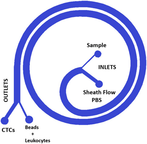
FIGURE 1. Design of the single spiral. The spiral design is used for standard lithography and for 3D printing, a microfluidic device that enables first the separation of CTCs from a blood sample and second the purification of the obtained CTC sample reducing the concentration of Leukocytes. The blood sample is introduced into one of the device’s two inputs and then flows through the spiral channel. As the blood flows through the spiral, it is subjected to centrifugal forces, which causes the CTCs to migrate towards the outer wall of the spiral while the other components such as beads and leukocytes move towards the center. This separation is then facilitated by the device’s two outputs, with the CTCs being directed towards one output while the beads and leukocytes are directed towards the other. This design allows for the efficient and precise separation of CTCs from a blood sample, which can then be used for various diagnostic and therapeutic applications.
The spiral design enables precise control of flow rate and pressure, allowing for efficient concentration of CTC reducing the leukocyte contamination. By using this cutting-edge microfluidic technology, we are able to concentrate CTCs with greater accuracy and effectiveness.
The effect of the separation of cells and beads for the 3D spiral microfluidic designs can be seen in Figure 2. Before fabricating and testing the device, a numerical analysis was executed using COMSOL Multiphysics 5.6. The geometry of the spiral channel used in simulations was created in Auto CAD and imported into COMSOL. The geometry was then extruded for different heights, to create separate simulations for different heights of the device. To simulate how particles behave inside the spiral, the Computational Fluid Dynamics (CFD) module and Particle Tracing module were used. The CFD module enables simulating of a continuous flow field inside the device, and the Particle Tracing module was used to solve several discrete trajectories. Hence, the device was utilized to simulate and monitor the actions of white blood cells (WBCs) and circulating tumor cells (CTCs). The simulations resulted in the release of particles, which were separated into two distinct devices. The first device, designed with a size threshold of 12 microns, aimed to distinguish CTCs from red blood cells (RBCs) and small leukocytes. Subsequently, a second spiral microfluidic device with a size threshold ranging from 50 to 60 microns was employed to eliminate bead-trapped WBCs measuring between 70 μm and 100 µm. This process facilitated the purification of the initially obtained CTC sample.
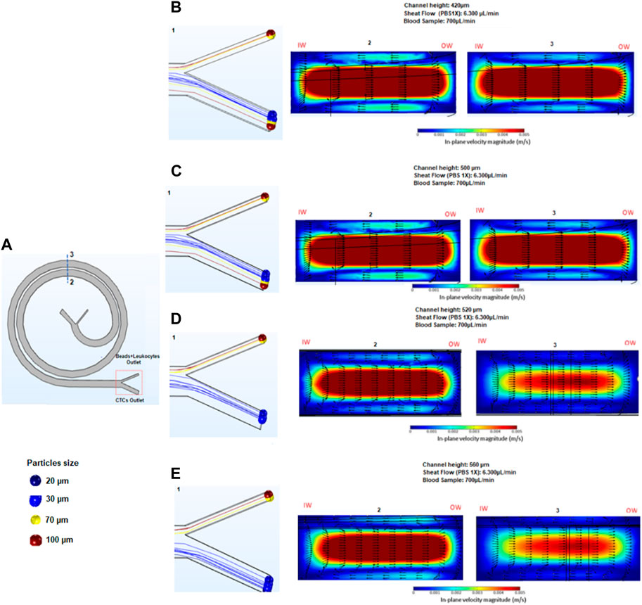
FIGURE 2. Results obtained in COMSOL. The figure shows a 2D view of a COMSOL simulation of the spiral microfluidic device with particles of different sizes introduced into the system, represented by different colors. The simulation is used to analyze the behavior of the particles as they flow through the spiral channel. By tracking the trajectories of the particles, the efficiency of the device in separating particles of different sizes can be studied.
The primary objective of the second stage of bead separation is to achieve the purification of CTCs from leukocytes. As these two cell types possess similar sizes, leukocytes are targeted for removal by attaching them to beads, thereby increasing their overall size. The new device design facilitates the subsequent separation of the enlarged bead-bound leukocytes from the CTCs. To determine the most effective device height for efficient bead separation, simulations were carried out using devices of varying heights: 550, 600, 700, and 800 microns. The selection of these heights was based on the estimated outcomes derived from Eq. 1, as outlined in Table 1. By employing this approach, the optimal device height for successful bead separation and subsequent CTC purification could be determined accurately.
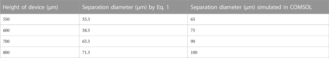
TABLE 1. Description of Height of spiral devices for separation of beads >50 µm.
In order to further enhance the purification capability of our spiral microfluidic devices combined with beads, we have developed a design compatible with 3D printing that features two interconnected spirals, as shown in Figure 3. This new approach involves the fabrication of two different spirals, each 3D printed in different planes, that work in tandem to maximize CTCs purification.
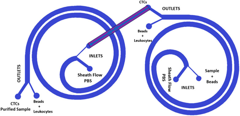
FIGURE 3. Design of the two interconnected spirals. The two blue spirals are placed in different planes; thus, the red channel is inclined. The new design is a double spiral microfluidic device that can be 3D printed thanks to its inclined channel, which enables double filtration of the blood sample.
SL is a unique form of 3D printing that utilizes a liquid photo resin precursor and a digital light-processing (DLP) projector to create complex 3D structures. The resolution of printed features in the XY-plane is primarily determined by the projected pixel size, the absorption properties of the photo-resin, and the reactant diffusivity. However, the resolution in the Z-direction is limited by the minimum step that can be achieved by the building platform. Previous studies have shown that SL has a higher resolution in the XY-plane than in the Z-direction. Additionally, printing cantilever structures can be challenging as light can penetrate through the resin and affect the Z-resolution. To observe fluids within channels under a microscope, a transparent resin is required, which must be polymerized using UV light. The minimum cross-sectional area of a microchannel that can be achieved by SL also depends on the type and viscosity of the resin, which must be effectively drained post-printing. Recently, desktop SL systems based on DLP projectors have become increasingly popular as an alternative to soft lithography due to their high resolution and cost-effectiveness (Waldbaur et al., 2011; Gross et al., 2014; Ho et al., 2015; Bhattacharjee et al., 2016; Li et al., 2019; van der Linden et al., 2020; Subirada et al., 2022).
The 3D printing resin used was Detax Freeprint Ortho, for DLP printers with a wavelength of 385 nm, and it is clear, transparent, and biocompatible, based on ISO 10993-1:2010 (Guttridge et al., 2022; DETAX, 2023a). One notable advantage of this material is its high construction precision and stability, which makes it ideal for use in applications that require accurate and reliable performance. Additionally, the material is MMA-free and neutral in odor and taste, making it safe and comfortable for use in sensitive applications. Its fracture resistance, elasticity, and moisture influence are also in accordance with orthodontic standards, further highlighting its suitability for use in medical and dental contexts. The material is also easy to sterilize in autoclaves, with a validated procedure for this purpose. Furthermore, the manufacturer presents remarkable physical data for the resin, including a flexural strength of over 75 MPa, a modulus of elasticity of over 1,650 MPa, and a final hardness of over 82 Shore D. Its low water absorption and solubility rates of less than 32 μg/mm³ and 5 μg/mm³, respectively, further demonstrate its durability and reliability (DETAX, 2023b).
Figure 4 shows three images illustrating designs for 3D printed microfluidic components. These include 3D printed microfluidic channels, and an inclined microfluidic channel, enabling operation in two different planes.
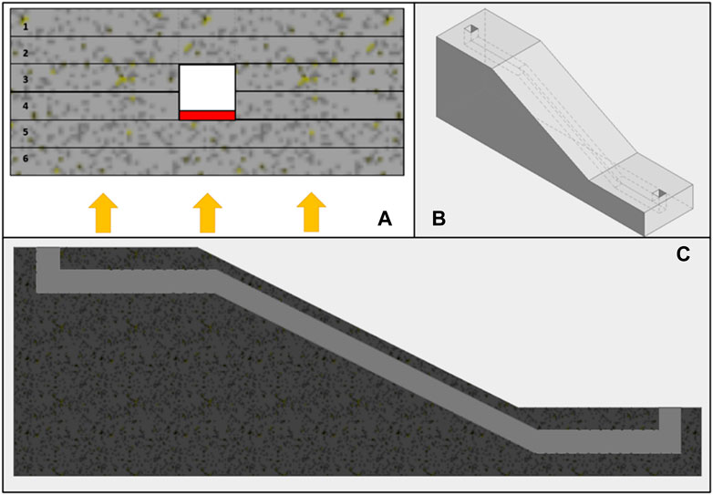
FIGURE 4. (A) shows the section of a microfluidic channel, differentiating the various layers of the device, numbered from 1 to 6. Layers 1 and 2 represent the base of the device, while layers 3 and 4 comprise the formation of an open channel. Layers 5 and 6 present greater complexity due to the potential for the UV light used in printing to block the open channel from previous layers. The red area in the channel (layer 4) shows where the flow can be blocked by the UV light used in printing, which must be carefully controlled to prevent blockages. The arrows at the bottom of the image represent the direction of the UV light emitted by the DLP projector. (B) provides an overall view of a design with an inclined channel that enables transition between planes and enables more complex and customized models. Finally, (C) is a cross-sectional view of the component design shown in (B), clearly showing the angled microfluidic channel. Together, these images provide a detailed description of the designs of 3D printed channels, channels with features, and angled microfluidic channels.
Among the label-free systems for the enrichment of target cells in complex fluids including cells with different cells as human blood, microfluidic devices based on inertial focusing are one of the most promising (Iv et al., 2015; Civelekoglu et al., 2022). Overall, spiral device designs have been reported for isolating CTCs from blood by applying inertial forces. Normally, the inertial lift forces and drag forces are orthogonal on a particle. Nevertheless, in a curved channel, a secondary cross-sectional flow starts to appear (Dean flow), which triggers the particles to experience a drag force on the same axis as the shear gradient and the wall effect lift forces (Chung, 2019). As a result, the balance between these forces causes different equilibrium positions of particles depending on their size. Thus, small particles follow the Dean flow while big particles are under a stronger lift force.
The basic spiral microfluid device is composed of two inlets (A and B) connected to a unique microfluidic circular channel wound concentrically in a spiral that finally splits in two outlets. Inlet A is pumped with PBS 1X to focus the fluid sample on the outer wall, and inlet B is pumped with the sample fluid that includes the target cells. Successful separation of the target cells occurs thanks to the combination of the effect of two forces [inertial lift force and Dean drag force (FD)].
Figure 5 shows one spiral 3D printed device, which is designed to be able to separate individual or cluster cells and beads based on their size. For instance, to isolate CTCs from a blood sample. The device consists of a spiral channel that increases in radius every half lap, with a total of two and a half laps. The device has two inputs, one for a blood sample and one for PBS 1X. The device is transparent, allowing for easy observation of the results under microscopy, and is biocompatible, making it suitable for use in biological experiments. The dimensions of the channel are 1.4 mm in width, 0.4 mm for the smaller input and output which contains the blood sample and therefore the CTCs, and 1 mm for the wider inputs and outputs which are used for PBS 1X and waste respectively. The aim is to perform the separation of CTCs with increased purity and reduced contamination. The influence of channel height has been tested between 600 μm and 800 µm and optimized accordingly. These channel dimensions were chosen due to the capabilities of the 3D printer presented by Subirada et al. (Subirada et al., 2022).
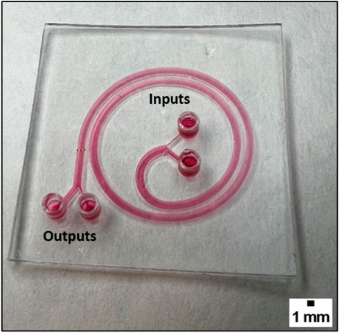
FIGURE 5. The picture shows a 3D printed device, which consists of a spiral with a channel of 1.4 mm width and 600 µm height.
The device shown in Figure 5 was improved by adding a second spiral in a different plane, as shown in Figure 6. To ensure the inclined channel was not obstructed while printing the channel height was modified to 800 µm. This novel design leverages the purified CTCs obtained from the first spiral device as the input for the second spiral device, thereby enhancing the separation efficiency. The use of 3D printing made this innovation feasible since the second spiral was printed on a different plane than the first one, which is not achievable with traditional lithographic fabrication techniques.
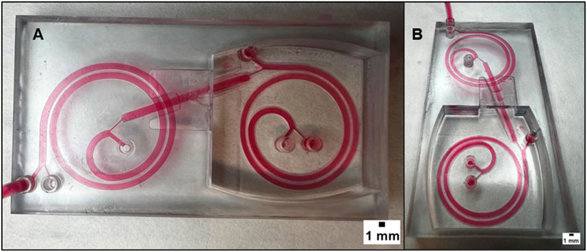
FIGURE 6. (A) displays the superior view of a microfluidic device that combines two spirals in order to enhance its performance. The device has two spirals in different planes, and this figure provides an overview of the device’s structure and design. (B) provides a different point of view of the device. It can be observed that the two spirals are arranged in different planes and that there is an inclined channel that connects them. The realization of this design is possible thanks to the 3D printing technology, which offers the flexibility and precision necessary to create complex geometries that cannot be achieved with traditional manufacturing methods. The dimension of the channel is 1.4 mm in width with a height of 800 µm.
The dimensions of the channels within the microfluidic device were studied using test structures as shown in Figure 7. The results of the fabrication confirmed that the channel cover was slightly thicker than the intended design. This deviation in dimension is attributed to the UV radiation from the DLP printer, which penetrates the cover and enters the channel, curing a small amount of resin that should have remained uncured, as it was shown in Figure 4A. The deviation in dimensions was found to have a minimal effect on the overall performance of the device, and further optimization of the printing process can be done to mitigate this issue.

FIGURE 7. The figure shows two different views of the section of the double-spiral device, 3D printed with Detax resin. This has been created by using a slicing software to cut a portion of the complete device, to uncover the interior of the channels. It shows the printed dimensions of the channels, and any deviations from the intended design would be noticed.
With the sections of these 3D printed channels, their measurements were compared to the intended design. The cover of the upper spiral was observed to be 252 μm, which is 52 µm more than the intended 200 µm. This indicates that extra polymerization occurred due to the penetration of UV radiation from the DLP printer, meaning that the UV light cured a small amount of resin that should have remained uncured. As a result, the channel height ended up being 748 μm, instead of the intended 800 µm. Similarly, the cover of the lower spiral was observed to be 276 μm, indicating that a slight amount of extra cured material was present. This was because the lower spiral was printed before the upper spiral, and therefore received a higher dose of UV light energy directly or through diffusion. This resulted in the channel height being measured at 724 μm, rather than the 800 µm that was intended.
In microfluidic applications, syringe pumps have traditionally been used to modulate a small amount of liquid flow. However, when used in spiral microfluidic devices for liquid biopsies, they require large and complex setups, as shown in Figure 8A, and have several drawbacks. First, they do not allow the recirculation of the sample multiple times. Second, when processing large blood volumes, the syringe must be frequently refilled, which leads to the loss of circulating tumor cells (CTCs) as the flow stabilizes following the replacement of the sheath flow syringe. Additionally, the blood sample tends to settle in the syringe, requiring continuous rotation to ensure a homogeneous mixture. Finally, the setup takes up a significant amount of space and is not portable, making it challenging to fit easily in clinical laboratories.
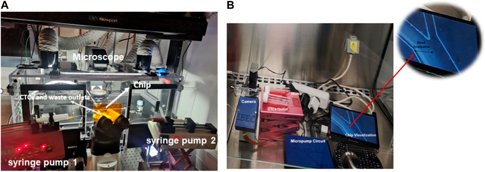
FIGURE 8. (A) Traditional microfluidic set-up for isolating CTCs using a spiral device. The system is composed of two syringe pumps, two reservoirs connected to the outlet of the microfluidic channel, and one microscope. (B) Compact biocompatible flow platform allows to check the blood focalization in bright field.
To address the limitations of traditional syringe pumps for liquid biopsies in microfluidic devices, a flow compact circuit has been developed using commercial piezoelectric pumps (Bartels MP6) which are controlled by a Raspberry Pi zero microcontroller, as shown in Figure 8B. Micropumps are piezoelectric in combination with passive check valves. Thus, a piezo ceramic put on a coated brass membrane is deformed when voltage is applied. Then, the medium is displaced out of the pump chamber below. The check valves on both sides of the pump chamber define the flow direction. By using piezoelectric pumps, this flow control circuit offers several advantages over traditional syringe pumps. For instance, piezoelectric pumps do not require a separate syringe, thus eliminating the need for frequent filling, and reducing the loss of CTCs. Moreover, the compact size and portability of the piezoelectric pump setup make it more convenient for use in clinical laboratories.
The circuit is composed of a small driving circuit (mp-Lowdriver) for mp6 micropumps, useful for low flow rate applications (8 μL/min up to 4.000 μL/min) and high amplitude resolution. These micropumps display some drawbacks, such as high pulsation of the flow and a lifetime of around 5.000 h. Nevertheless, these disadvantages can be overcome by integrating mp-dampers into the system, which allows for reduced pulsations in the flow generated by the micropump, and consequently, a more stable flow rate is achieved (Figure 9B; Supplementary Figure S1; Supplementary Table S1). Finally, the circuit has a passive check valve (mp-cv) that prevents the medium or blood from flowing back when the pump is switched off. Although pumps can be sterilized to prevent cross-contamination by autoclaving for 20 min at 121°C and 10% of EtO, it is more cost-effective to replace them weekly if they are manufactured on a large scale than to undergo repeated sterilization procedures (Zhang et al., 2016). To address other limitations of conventional set-ups a small microscope (XPD-101 Expedition Bresser) was adapted to a Raspberry pi camera (Raspberry Pi Camera 12.3 MP IMX477 Sensor), shown in Figure 9A. This camera has been controlled with the Raspberry Pi Zero at the same time and will allow to visualize and monitor the blood cell focalization towards the waste outlet using real samples from patients with cancer, which will not be stained with a fluorescent biomarker, and the correct functioning of the chip can only be evaluated through the visualization of the depletion of blood cells as shown in Figure 9C (white arrow). Therefore, the correct functioning of the system for the separation of cancer cells with a size greater than 12 µm was previously validated using the conventional system of fluorescence microscopy and labelling the cytoplasmic membrane of cancer cells with a fluorescent dye, as shown in Figure 9B. Overall, the system exhibits various features that increase its programmability, portability, and affordability, ultimately enhancing its versatility and adaptability to clinical laboratories.
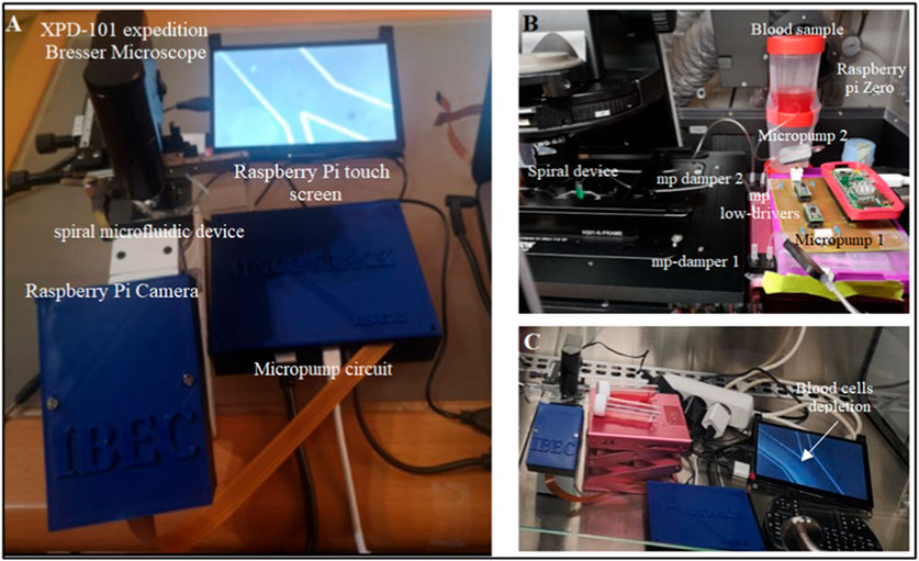
FIGURE 9. (A) Portable biocompatible flow platform composed of Raspberry Pi Camera 12.3 MP IMX477 Sensor, micropump circuit, Raspberry Pi touch screen, and one small microscope (XPD-101 expedition Bresser). (B) Micropump circuit composed of two small micropumps and two mp low-drivers controlled by one Raspberry Pi Zero, two mp dampers and check valves. The system has inlet and outlet reservoirs that can be filled without shutting down the system and allows sample recirculation. (C) The depleted blood cells can be recorded and visualized in real time in Bright field.
The operation of micropumps was evaluated with a single spiral microfluidic device made of PDMS fabricated with standard lithography previously described. Thus, the spiral device was tested with 10X diluted blood samples from healthy donors spiked with a final concentration of 1.000 cells/mL of different sizes such as MCF-7 (20 µm) and A549 (15 µm). The sample was perfused through the inlet A of Figure 10A of the spiral microfluidic device using the portable biocompatible flow platform, applying an SRS-signal and voltage 125Vpp with a frequency of 41 Hz (3,300 μL/min),. Meanwhile, the sheath flow (PBS 1X) was perfused through the inlet B, as seen in Figure 10A, and the parameters were set to 150 Hz and a voltage of 125 Vpp (7,700 μL/min). Furthermore, some mp-dampers were included in the electronic circuit to reduce the effect of pulsation on the flow, which affects the separation efficiency, as shown in Figure 10B. Figure 10C shows the reduction of flow pulsation, which leads to flow stability and the hydrodynamic focalization of the blood sample through the outer wall, being one of the key parameters for the larger CTCs (>12 um) undergoing inertial focusing. Moreover, passive check valves were added to prevent the medium from flowing back when the pump is switched off.
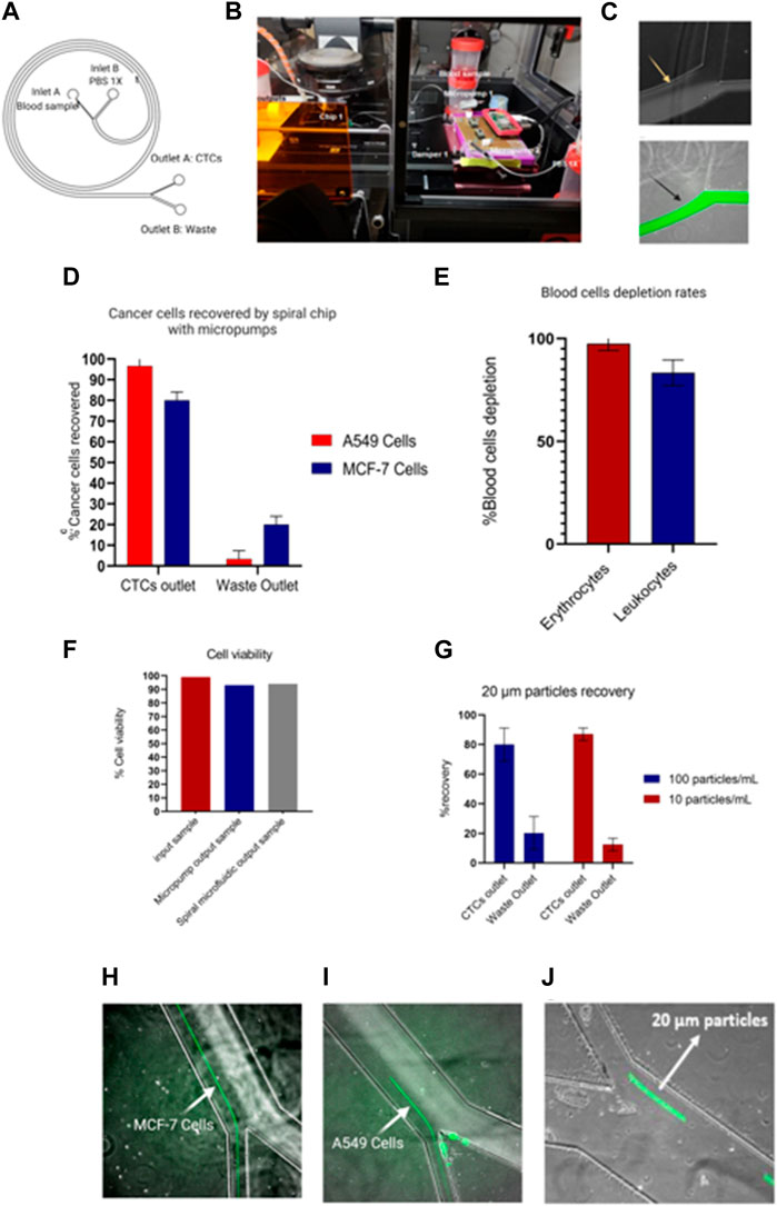
FIGURE 10. Portable flow platform tested with blood samples from healthy donors spiked with cancer cell lines. (A) Schematic representation of spiral microfluidic device composed by inlet A (10x blood sample), inlet B (PBS 1x), outlet B (waste), outlet A (CTCs outlet). (B)circuit composed of two micropumps, mp-low drivers programable by a Raspberry pi Zero, mp-damper and passive check valves (mp-cv). (C) Hydrodynamic non-focalization of blood sample because of pulsation on the flow (yellow arrow) vs. sample focalization of sample with mp-dampers included (black arrow). (D) Recovery efficiency of A549 and MCF-7 cells by spiral chip using micropumps. Values and error bars represent mean ± S.E.M (n = 3). (E) Depletion rates of blood cells. Values and error bars represent mean ± S.E.M (n = 3). (F) Cell viability test of cancer cells passing through the micropumps and spiral microfluidic device. The bars represent the average. (G) Recovery rates of low concentration of 20 µm particles as a CTC model. Values and error bars represent mean ± S.E.M (n = 4). (H–J) Separation of cancer cells (MCF-7 and A549 cells) and 20 µm particles stained in green.
On the other hand, the samples recovered from outlet A (Figure 10A-CTCs outlet) were analyzed by flow cytometry and revealed a recovery efficiency of 80% ± 4% for MCF-7 cells and 95% ± 4% for A549 cells (Figures 10D, H, I). In addition, the system enables 97.5% ± 1.89% and 83.4% ± 3.6% depletion of erythrocytes and leukocytes respectively (Figure 10E). Further analysis of the cell viability of the CTCs outlet demonstrated that the micropump and the spiral microfluidic devices allow for recovery cells with a high viability of 93% ± 0.12% and 94% ± 0.23% respectively, as shown in Figure 10F, which can be used for subsequent downstream analyses. Our finding suggests that our system could achieve an increase in the cancer cells recovery rate of 10% ± 4% compared with the previous results reported by Warkiani et al. In contrast, the leukocyte depletion rates differ from the values reported by Warkiani et al. by a reduction of the leukocyte depletion of 17% (Warkiani et al., 2016).
An implication of the finding exposed is the throughput of the platform in terms of blood processing, which is equivalent to 3.3 mL/10 min (Warkiani et al., 2016). Despite not being consistent with those reported by Warkiani in lysed blood samples (7.5 mL/10 min), it represents an improvement over the data reported by Hou and others using samples with high hematocrit of 20%–25% and a throughput of 3 mL/h in a chip with similar microchannel dimensions of 500 μm (w) × 160 μm (h) (Ensensetech, 2022). In our specific scenario, the flow rate required to achieve an ideal separation of the CTCs differed from the values reported by Hou and others. This variance was primarily attributable to the performance of the micropumps. It was noted that ensuring the microfluidic channel’s flow stability necessitated not only the inclusion of a damper in the circuit but also its effective operation at higher flow rates.
Finally, the system was tested with a low concentration of 20 µm particles as a CTCs model (100 particles/mL and 10 particles/mL) in diluted 10 × human blood samples. In particular, the quantification of the recovery CTCs model sample was performed by videos since the correct analysis by flow cytometry was limited to the low cell concentration. Therefore, the results showed a recovery of 80% ± 11.2% and 87% ± 4.3% for 100 particles/mL and 10 Particles/mL, as shown in Figures 10G, J. Here, it could be expected that similar recovery rates for low concentrations will be obtained with cancer cells. Nevertheless, a bias should be considered due to other cell properties that can alter the separation yield, like cell deformability.
Overall, the results demonstrate that this instrumentation platform is suitable for spiral microfluidic devices used for the separation of particles or cells with different diameter and allows its potential application in liquid biopsy to recover a high rate of CTCs, with greater flexibility and scalability compared to traditional pump systems. Moreover, this system displays some advantages as a label free or independent antigen method, since the CTCs are collected in a solution that could be cultured for subsequent analysis, as well as the possibility of not using intermediate steps, such as blood lysis, that could promote the loss of CTCs. However, some drawbacks must be considered, such as the loss of smaller CTCs.
Therefore, as previously mentioned, new enrichment methods are needed to purify the sample obtained with the CTCs and reduce the leukocyte background. For that purpose, developing a single spiral microfluidic device made from 3D printing could help increase leukocyte depletion. To test the performance of the 3D spiral microfluidic devices fabricated, a blood sample without cancer cells was first processed as previously described (Figure 10). The blood sample output obtained from outlet A (Figure 10A), which would include the leukocytes that contaminate the CTCs sample, was incubated with 70 µm diameter microspheres conjugated with Biotin-CD45 antibodies (Figures 11A–C) and after the sample introduced in the 3D printed microfluidic spiral to remove the beads. The results revealed that around 48% of leukocytes were captured by the beads as shown in Figures 11D, F. Moreover, through the capture of microscope fluorescent images, it was possible to demonstrate that most of the 70 µm particles without bonded leukocytes could be separated and take the “Leukocytes + beads outlet”. Accurate quantification of recovered 70 µm particles using flow cytometry was not found due to obstruction caused by particle size. Analyzing the particles detected in the video frames, we have obtained that the device shows a recovery rate of 75% ± 17%, as shown in Figure 11G.
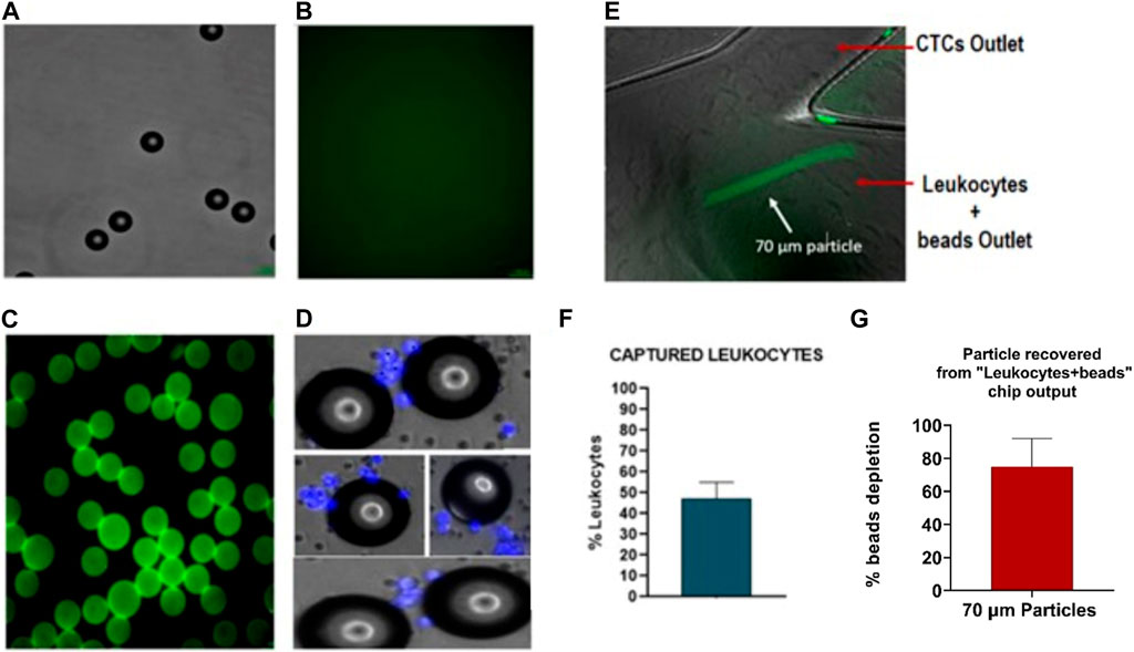
FIGURE 11. Characterization of polystyrene particles binding to CD45-antibody: (A) Polystyrene particles of 70um in Bright field (BF). (B) Negative control for Biotin-CD45. (C) Polystyrene particles binding with biotin-CD45 antibody and secondary antibody AlexaFluor 488. (D). Polystyrene particles are binding with leukocytes (nucleus stained in blue). (E) Microscopy images of 70 µm particles (green) focalized through of outer wall. (F) Quantification of particles binding to leukocytes with an efficiency around 48%. (G) Quantification of 70 µm depleted from the sample (75% ± 17%). Values and error bars represent mean ± S.E.M.
Therefore, drawing from the computational findings presented in Figure 2 and the initial optimization process, which centered on the percentage of leukocytes captured by the beads and the particle separation observed in microscope images, we postulate that this device has the potential to effectively separate smaller particles representing cancer cells or CTCs (>12 µm) from streptavidin-coated CD45 particles, which are approximately 70 µm in size. Moreover, considering all the results together exposed in Figures 10, 11, we propose that combining a microfluidic spiral to separate particles >12 µm with the 3D microfluidic spiral to separate particles as the beads coated with CD45+ antibodies could be possible to achieve a total leukocyte depletion up to 91%, and a maximum recovery of cancer cells up to 95%, which would represent an increase in the cancer cells recovery rate compared to the results reported by Warkiani et al.
Finally, thanks to the devices developed, it is not needed to perform extra sample centrifugations, which increase the risk of losing CTCs. In contrast, our system could represent a new approach to CTC separation by combining inertial forces microfluidic devices, antibody binding approaches, and 3D printing methods that have not been widely reported until now, which could allow higher leukocyte and erythrocyte depletion rates. Nonetheless, further work is needed to develop reliable quantification methods for the easy implementation of this system.
In conclusion, different spiral microfluidic devices using standard lithography and 3D printing have been designed and fabricated, generating a modular system that allows to collect cancer cells from blood samples and reduces the leukocytes contamination of the sample obtained. The technique of SL has been successfully applied in the production of microfluidic devices for negative enrichment using Detax resin. The use of 3D printing technology in the design and manufacturing of microfluidic devices enables greater flexibility and customization, allowing the development of new microfluidic devices, such as the single or double spiral microfluidic device for cancer cell enrichment.
The use of microfluidic devices for the separation and purification of cancer cells has shown promising results. The COMSOL simulation of the spiral microfluidic device and the determination of optimal device height through simulations have provided valuable insights into the behavior of particles in microfluidic devices, leading to the design of more effective devices such as the newly developed double spiral microfluidic device. The successful separation of beads could allow the purification of cancer cells from leukocytes, highlighting the potential of microfluidic devices in diagnostics and personalized medicine. Further research and optimization of these devices have the potential to significantly advance our understanding of cancer and improve patient outcomes.
The economics of 3D printing are well-suited for microfluidics as the cost per device does not increase with 3D complexity and is not affected by the size of the production batch. Therefore, SL is ideal for project customization and scalability.
Additionally, we have developed a low-cost, portable, and scalable flow read-out platform that is easy to use and fully programmable. This platform can be used together with spiral microfluidic devices for cancer cell isolation and can also be adapted to other fluidic applications. The results have demonstrated the feasibility of using micropumps for isolating viable cancer cells (>90%), and the ability to replace traditional syringe pumps with high-efficiency cancer cell separation using microfluidic spiral devices (>80%).
In summary, the combination of 3D printing technology, COMSOL simulation, and innovative microfluidic designs has led to significant advancements in the field of CTCs separation and purification. These developments have the potential to revolutionize cancer diagnosis and treatment by providing more accurate and efficient methods of detecting and analyzing CTCs. The optimization and clarification of these microfluidic devices and their technologies will definitely have a profound impact on the field of cancer research and personalized medicine. This is crucial for improving the accuracy and efficiency of CTC separation and detection, which can have important implications for cancer diagnosis and treatment.
Several key components were selected to customize the 3D printer, including the DLP UV light projector, Z motors, plate holder, resin container, and an open-source hardware solution that was implemented.
The open-source hardware system that we chose for the 3D printer consists of two parts: a Raspberry Pi embedded computer and the open-source Reprap Universal Mega Board with Allegro driver (RUMBA) controller board. The RUMBA board is released under the GNU Public License (GPL) v2.0 by reprapdiscount.com, and the Raspberry Pi runs NanoDLP front-end and control software, which can be downloaded from nanodlp.com. This software enables customization of the entire printing process and provides a slicer and a web interface that can be accessed remotely. The software communicates with the open-source Marlin firmware which runs on the RUMBA board and controls the movement of the axes. The Marlin firmware is released under GPL v3.0 and was configured to control the two Z-axis motors through two different optical end-stops based on the tcst2103 sensor for reliable alignment at each power-cycle.
Additionally, the DLP projector used in our customized 3D printer is the Wintech PRO6500, based on the DLP6500 Digital Micromirror Device (DMD) by Texas Instruments. It features a UV DLP LED system with a resolution of 1920 × 1,080, a projected pixel size of 50 μm at a fixed working distance, and a peak wavelength of 384 nm. The projector is equipped with standard HDMI, DisplayPort, USB, and I2C ports for video input and control respectively. A custom program was written to control the LED status and intensity over USB protocol, and this was integrated into the frontend software (NanoDLP).
For the resin container, we used the “Resin Vat Anodized Aluminum with Fluorinated Ethylene Propylene Film (FEP) from ANYCUBIC”. The plate holder is a custom-designed component that holds a standard 50 × 75 mm glass slide with a vacuum system, using alignment pins on the platform. This plate holder was designed with a matte black finish to minimize light reflection.
All 3D printing was conducted in a yellow-light room to ensure that the resin was only exposed to UV light from the DLP UV projector. The printing chamber was preheated to 30°C to maintain consistent properties of the resin. Before starting the printing process, the Raspberry Pi, Z motors, and DLP projector were turned on. The vat was checked to ensure it contained enough resin for the piece to be printed, and the 50x75 mm glass slide, on which the 3D printed piece attaches, was aligned properly. The printing process was then executed using the NanoDLP software, which automatically slices the previously uploaded drawing and controls the printing process based on various parameters such as layer thickness, exposure time, and light intensity. This process was executed remotely, outside the yellow-light room, to avoid UV radiation.
Once the printing process was completed, the piece was washed for 2 minutes in 2-Propanol and thoroughly cleaned with compressed air, focusing on the microfluidic channels to remove any remaining uncured resin. The piece was then washed for an additional 2 minutes in 2-Propanol and post-cured for 2 minutes in a UV light washing and curing machine from CREALITY.
The optimal printing parameters were determined through dose calibration experiments, where motives were exposed to UV light for varying time steps ranging from 1 s to 5 s seconds.
To develop the instrumentation platform, the control and read-out system using microfluidic devices obtained by standard lithography were tested and improved. Briefly, a silicon wafer of 4” inches (10 cm × 10 cm) was employed as a substrate. After, two layers of the photo-resin SU8 3,050 were spin-coated. Subsequently, the silicon wafer was immersed in SU8 developer for 15 min, rinsed with isopropanol, and dried with N2. Then, the hard baking process was performed for 30 min at 95°C and 10 min at 65°C. Finally, the wafer was salinized in a vacuum desiccator for 1 h with a drop of trichloro (1H,1H,2H,2H-perfluorooctyl) silane (Sigma Aldrich) in a glass or a petri dish. The final microfluidic spiral devices were replicated in polydimethylsiloxane (PDMS).
The microfluidic devices for the first discrimination procedure with a threshold of 12 microns were fabricated using the standard soft lithography technique (Zhang et al., 2016). Briefly, a silicon wafer of 4” inches (10 cm × 10 cm) was employed as a substrate. The substrate was prepared through a dehydration process on a hot plate at 200°C for 15 min and plasma cleaner for 1 min at high frequency (RF). After, we spin-coated two layers of the photo-resin SU8 3,050. The first layer was spin-coated to 500 rpm-Ac 100 rpm for 30 s (first step) and 1900 rpm-Ac 300 rpm for 30 s, the second one to 500rpm-Ac 100 rpm (first step) for 10 s and 3,000 rpm-Ac 300 rpm for 30 s (Second layer) to get a channel height of 150 µm. Then, the acetate mask was exposed with an I-line filter (Energy = 270 mj/cm2/13, 7 mW/cm2). After the resin diffusion for 5 min, the post bake process was performed in two steps (5 min at 65°C and 12 min at 95°C). Subsequently, the silicon wafer was immersed in SU8 developer for 15 min, rinsed with isopropanol, and dried with N2. Then, the hard bake process was performed for 30 min at 95°C and 10 min at 65°C. The final microfluidic spiral devices were replicated in polydimethylsiloxane (PDMS). The inlets and outlets holes of 1.0 mm were punched and the PDMS devices were irreversibly bonded to glass with plasma (Harrick Plasma Cleaner, United States).
In both fabrication procedures, the final microchannel dimensions were verified by interferometer and profilometer. To determine the dimensions of the resulting devices, an optical microscope (Nikon Eclipse L150, Nikon) was used. And to determine the section of the 3D printed channels and the dimensions of the printed features, an inverted microscope (Eclipse Ti, Nikon) and a profilometer were used.
The flow platform was fabricated using micropumps MP6-OEM Bartels, two mp-low drivers controlled by Raspberry Pi zero. A custom-built PCB designed in Eagle with Molex connectors was used for connecting the components. In addition, two check valves (BT-mp-cv) and two mp-dampers were connected to the micropump outlets.
The Raspberry Pi touch screen and Raspberry Pi Camera 12.3 MP IMX477 Sensor were connected to Raspberry Pi zero, and a portable microscope XPD-101 expedition Bresser was also included in the platform. Python was the programming language used to implement the Raspberry Pi and its external devices.
Human breast adenocarcinoma cell lines, MCF-7 cell line was used to mimic CTCs (size: 20 μm). Also, non-lung small cancer cell lines were considered to mimic smaller CTCs A549 (size: 15 μm). The MCF-7 cells were cultured in Roswell Park Memorial Institute medium (RPMI 1640-ThermoFisher Scientific), supplemented with 10% FBS, 1% L-glutamine, and 1% penicillin-streptomycin. A549 Cells were cultured in Dulbecco’s MEM (DMEM) supplemented with 10% FBS and 1% penicillin-streptomycin. The cells were maintained at 37 °C in a humidified atmosphere containing 5% CO2, and sub-culture every 3 days using Trypsin-EDTA (0.25%), phenol red (Gibco™).
MCF-7 and A549 cells were suspended at a density of 1×10⁶ cells/mL in RPMI medium supplemented with 10% FBS, 1% L-glutamine, and 1% penicillin-streptomycin. Then, 10 µL of CellBrite Greeen™ or CellBrite Red™ (Cytoplasmic Membrane Dyes-Biotium) solution was added per 1 mL of cell suspension. The solution was mixed well by flicking the tube. After, the cells were incubated for 20 min at 37°C, in the dark. Subsequently, cells were pelleted by centrifugation at 500 g for 5 min. Finally, the supernatant was removed, and the cells were washed gently, resuspending them in the warm medium at 37°C. The centrifugation and washing steps were repeated two more times. Finally, the cell suspension was diluted to achieve the cell concentration used in the experiments (1x10⁴ cells).
Blood samples were obtained from healthy volunteers and acquired from the Blood and Tissue Bank in Barcelona (up to 36 h from its extraction). Blood samples were used as controls with the previous approval of the committee on research ethics with medicines and the commission of research projects of the Vall d’Hebron University Hospital.
Whole blood obtained from healthy donors was diluted 10X in PBS 1X to obtain a hematocrit level of 4%. The sample was spiked with 1x10⁴cells/mL of MCF-7, A549 cells labelled with CellBrite Green™ or CellBrite Red (Biotium) (final concentration in a diluted sample: 1,000 cells/mL). Also, a blood sample was spiked with 20 µm particles as a CTC model and diluted 10X in PBS 1X. 1,000 and 100 particles/mL for high speed were recorded with fluorescence (final concentration in a diluted sample: 100 and 10 particles/mL). To study and focus particles, high-speed imaging and flow cytometry (FACs) were performed. Flow-Check Pro Fluorospheres (Beckman Coulter) were added to the sample (dilution 1:10) to quantify the number of cells in flow cytometry. Samples without chip processing were considered a control for quantifying the ratio of CTC recovery.
The viability of MCF-7 cells was tested with Zombie Violet™ (100 µL PBS 1X + 1 µL Zombie Violet ™) after processing through the micropump and the spiral microfluidic device. The sample was fixed with paraformaldehyde 8% for 15 min and then centrifugated at 500 G for 5 min. The supernatant was eliminated, and the cleaning process was repeated one more time. The analysis of cell death was performed in flow cytometry (FACS).
Polystyrene particles of 70 µm conjugated with streptavidin (SPHEROTMSVP-800-4) were washed before use to remove the 0.02% NaN3 added as a preservative. First, the particles were resuspended by gently shaking the vial to obtain a homogeneous suspension. Then, 400 µL from the vial was added to a 2 mL Eppendorf tube. After, the tube was placed in a centrifuge at 1000 g for 20 min. The supernatant was removed by aspiration, avoiding touching the particle pellet with the pipette tip. Subsequently, the pellet was resuspended in 1 mL of buffer solution (10 mM Tris-HCI (pH 7.5), 1 mM EDTA and 2.0 M NaCI). Finally, the washing step was repeated and resuspended in 1 mL of PBS1X with CD45-Biotin (1:100) (Human Clone 5B1—LOTE 5190918251 de Miltenyi Biotec). The particles were incubated for 30 min at room temperature with gentle rotation. The particles coated with the biotinylated antibody CD45 were centrifuged two times at 1000 g for 20 min with PBS/BSA.
The particles coated with the biotinylated antibody CD45 were centrifuged at 1000 g for 20 min and resuspended in 1 mL of PBS1X with Goat Anti-Mouse IgG H&L Alexa Fluor 488 (1:100) (Thermo Fisher Scientific). The particles were incubated for 30 min at room temperature with gentle rotation. Thus, the presence of CD45 antibody on the particles surface was checked by fluorescence microscopy (Nikon Eclipse Ti2). Moreover, particles incubated only with secondary antibody were considered as a negative control.
The sample recovered from the first spiral device was stained with Hoechst (1:10.000) (Thermofisher −33342) and incubated with the particles coated with the biotinylated antibody CD45 for 30 min with gentle rotation. The Leukocytes binding to the polystyrene particles were checked by fluorescence (Nikon Eclipse Ti2) and quantified using ImageJ.
The original contributions presented in the study are included in the article/Supplementary Material, further inquiries can be directed to the corresponding author.
The studies involving humans were approved by the Approval of the committee on research ethics with medicines and commission of research projects of the ValL d’Hebron University Hospital. The studies were conducted in accordance with the local legislation and institutional requirements. The human samples used in this study were acquired from a by-product of routine care or industry. Written informed consent for participation was not required from the participants or the participants’ legal guardians/next of kin in accordance with the national legislation and institutional requirements.
FS performed experiments, analyzed, interpreted the results concerning microfluidic 3D printing, and wrote the manuscript, JNS performed experiments, analyzed, and interpreted the results concerning instrumentation read-out platform and CTC cell model, and wrote the manuscript; RR interpreted the results and reviewed the manuscript; JS supervised the study, interpreted the results, wrote, and reviewed the manuscript. All authors contributed to the article and approved the submitted version.
The Nanobioengineering group in the Institute of Bioengineering of Catalonia (IBEC) has support from the Commission for Universities and Research of the Department of Innovation, Universities, and Enterprise of the Generalitat de Catalunya (2023SGR 015452) and is part of the CERCA Programme/Generalitat de Catalunya. This work is supported by the Project “001-P-001646 BASE3D” from Generalitat de Catalunya and European Regional Development founds to groups in emerging technologies for the realization of projects of valorization and transfer of research results. CIBER-BBN is an initiative funded by the VI National R&D&I Plan 2008-2011, Iniciativa Ingenio 2010, Consolider Program, CIBER Actions and financed by the Instituto de Salud Carlos III with assistance from the European Regional Development Fund. The authors acknowledge the support of “La Caixa” Banking Foundation (Understanding and measuring mechanical tumor properties to improve cancer diagnosis, treatment and survival: Application to liquid biopsies). Imaging was carried with the technical support of ICTS “NANBIOSIS,” Nanotechnology Platform, unit of CIBER-BBN at IBEC.
The authors would like to express their gratitude to the Nanobioengineering group and the Institute of Bioengineering of Catalonia (IBEC) for their support throughout this project. Special thanks to PhD student Sujey Palma from the Nanobioengineering group at IBEC for their expertise in imaging and for their contributions to the quality of figures. The authors also extend their gratitude to colleague, Sr. Jaume Gabarrella from Tartareu, for his exceptional CAD skills and for his invaluable assistance in designing the complex components of this project.
The authors declare that the research was conducted in the absence of any commercial or financial relationships that could be construed as a potential conflict of interest.
The author (JS) declared that they were an editorial board member of Frontiers at the time of submission. This had no impact on the peer review process and the final decision.
All claims expressed in this article are solely those of the authors and do not necessarily represent those of their affiliated organizations, or those of the publisher, the editors and the reviewers. Any product that may be evaluated in this article, or claim that may be made by its manufacturer, is not guaranteed or endorsed by the publisher.
The Supplementary Material for this article can be found online at: https://www.frontiersin.org/articles/10.3389/frlct.2023.1175668/full#supplementary-material
Au, A. K., Huynh, W., Horowitz, L. F., and Folch, A. (2016). 3D-Printed microfluidics. Angew. Chem. - Int. Ed. 55 (12), 3862–3881. doi:10.1002/anie.201504382
Bhattacharjee, N., Urrios, A., Kang, S., and Folch, A. (2016). The upcoming 3D-printing revolution in microfluidics. Lab a Chip 16 (10), 1720–1742. doi:10.1039/c6lc00163g
Chu, P. Y., Hsieh, C. H., and Wu, M. H. (2020). The combination of immunomagnetic bead-based cell isolation and optically induced dielectrophoresis (ODEP)-Based microfluidic device for the negative selection-based isolation of circulating tumor cells (CTCs). Front. Bioeng. Biotechnol. 8, 921. doi:10.3389/fbioe.2020.00921
Chung, A. (2019). A minireview on inertial microfluidics fundamentals: inertial particle focusing and secondary flow. BioChip J. 13, 53–63. doi:10.1007/s13206-019-3110-1
Cima, I., Yee, C. W., Iliescu, F. S., and Phyo, W. M. (2013). Label-free isolation of circulating tumor cells in microfluidic devices: current research and perspectives. Biomicrofluidics 7, 011810. doi:10.1063/1.4780062
Civelekoglu, O., Frazier, A. B., and Sarioglu, A. F. (2022). The origins and the current applications of microfluidics-based magnetic cell separation technologies. Magnetochemistry 8 (1), 10. doi:10.3390/magnetochemistry8010010
DETAX (2023a). Detax. Available at: https://www.detax.de/en/ueber-detax/zertifizierung.php.
DETAX (2023b). DETAX Freeprint 3D materials. Available at: https://sgdentalshop.com/wp-content/uploads/2019/03/DETAX-Freeprint-3D-catalogue-dental-materials-sgdentalshop.pdf.
Di Carlo, D., Irimia, D., Tompkins, R. G., and Toner, M. (2007). Continuous inertial focusing, ordering, and separation of particles in microchannels. Proc. Natl. Acad. Sci. 104 (48), 18892–18897. doi:10.1073/pnas.0704958104
Ensensetech (2022). Micropumps, EnSense. http://www.ensensetech.com/micropumps/.
Esmaeilsabzali, H., Beischlag, T. v., Cox, M. E., Parameswaran, A. M., and Park, E. J. (2013). Detection and isolation of circulating tumor cells: principles and methods. Biotechnol. Adv. 31 (7), 1063–1084. doi:10.1016/j.biotechadv.2013.08.016
Finehout, E., and Tian, W. C. (2009). Microfluidics for biological applications. New York, NY: Springer US. doi:10.1007/978-0-387-09480-9
Frenea-Robin, M., and Marchalot, J. (2022). Basic principles and recent advances in magnetic cell separation. Magnetochemistry 8 (1), 11. doi:10.3390/magnetochemistry8010011
Garcia, V. E., Liu, J., and DeRisi, J. L. (2018). Low-cost touchscreen driven programmable dual syringe pump for life science applications. HardwareX 4, e00027. doi:10.1016/j.ohx.2018.e00027
Gross, B. C., Erkal, J. L., Lockwood, S. Y., Chen, C., and Spence, D. M. (2014). Evaluation of 3D printing and its potential impact on biotechnology and the chemical sciences. Anal. Chem. 86 (7), 3240–3253. doi:10.1021/ac403397r
Gu, W., Zhu, X., Futai, N., Cho, B. S., and Takayama, S. (2004). Computerized microfluidic cell culture using elastomeric channels and Braille displays. Proc. Natl. Acad. Sci. 101 (45), 15861–15866. doi:10.1073/pnas.0404353101
Guttridge, C., Shannon, A., O’Sullivan, A., O’Sullivan, K. J., and O’Sullivan, L. W. (2022). Biocompatible 3D printing resins for medical applications: a review of marketed intended use, biocompatibility certification, and post-processing guidance. Ann. 3D Print. Med. 5, 100044. Elsevier Inc. doi:10.1016/j.stlm.2021.100044
Ho, C. M. B., Ng, S. H., Li, K. H. H., and Yoon, Y.-J. (2015). 3D printed microfluidics for biological applications. Lab. Chip 15, 3627–3637. doi:10.1039/c5lc00685f
Hou, H. W., Li, Q. S., Lee, G. Y. H., Kumar, A. P., Ong, C. N., and Lim, C. T. (2009). Deformability study of breast cancer cells using microfluidics. Biomed. Microdevices 11 (3), 557–564. doi:10.1007/s10544-008-9262-8
Hou, H. W., Warkiani, M. E., Khoo, B. L., Li, Z. R., Soo, R. A., Tan, D. S. W., et al. (2013). Isolation and retrieval of circulating tumor cells using centrifugal forces. Sci. Rep. 3, 1259. doi:10.1038/srep01259
Iv, C. W. S., Reyes, D., and López, G. P. (2015). Lab on a Chip in the separation of cells from debulking to rare. Lab a Chip. doi:10.1039/C4LC01246A
Kalpakli, A., Örlü, R., and Alfredsson, P. H. (2012). Dean vortices in turbulent flows: rocking or rolling? J. Vis. 15 (1), 37–38. doi:10.1007/s12650-011-0108-8
Kuntaegowdanahalli, S. S., Bhagat, A. A. S., Kumar, G., and Papautsky, I. (2009). Inertial microfluidics for continuous particle separation in spiral microchannels. Lab a Chip 9 (20), 2973–2980. doi:10.1039/b908271a
Kuo, A. P., Bhattacharjee, N., Lee, Y. S., Castro, K., Kim, Y. T., and Folch, A. (2019). High-precision stereolithography of biomicrofluidic devices. Adv. Mater. Technol. 4, 1800395. doi:10.1002/admt.201800395
Lake, J. R., Heyde, K. C., and Ruder, W. C. (2017). Low-cost feedback-controlled syringe pressure pumps for microfluidics applications. PLoS One 12 (4), e0175089. doi:10.1371/journal.pone.0175089
Lee, W. C., Bhagat, A. A. S., Huang, S., Van Vliet, K. J., Han, J., and Lim, C. T. (2011). High-throughput cell cycle synchronization using inertial forces in spiral microchannels. Lab a Chip 11 (7), 1359–1367. doi:10.1039/c0lc00579g
Li, F., Macdonald, N. P., Guijt, R. M., and Breadmore, M. C. (2019). Increasing the functionalities of 3D printed microchemical devices by single material, multimaterial, and print-pause-print 3D printing. Lab a Chip 19 (1), 35–49. doi:10.1039/c8lc00826d
Mosadegh, B., Mazzeo, A. D., Shepherd, R. F., Morin, S. A., Gupta, U., Sani, I. Z., et al. (2014). Control of soft machines using actuators operated by a Braille display. Lab. Chip 14 (1), 189–199. doi:10.1039/C3LC51083B
Naderi, A., Bhattacharjee, N., and Folch, A. (2019). Digital manufacturing for microfluidics. Annu. Rev. Biomed. Eng. 21, 325–364. doi:10.1146/annurev-bioeng-092618-020341
Ozkumur, E., Shah, A., Ciciliano, J., Emmink, B., Miyamoto, D., Brachtel, E., et al. (2013). Inertial focusing for tumor antigen-dependent and -independent sorting of rare circulating tumor cells. Sci. Transl. Med. 5 (179), 179ra47. doi:10.1126/scitranslmed.3005616
Parida, S., Dutta, S., and Pal, A. (2011). Hematological and plasma biochemistry in Psammophilus blanfordanus (Sauria: agamidae). Comp. Clin. Pathol. 21 (6), 1387–1394. doi:10.1007/s00580-011-1303-7
Sharafeldin, M., Jones, A., and Rusling, J. F. (2018). 3D-printed biosensor arrays for medical diagnostics. Micromachines 9 (8), 394–422. doi:10.3390/mi9080394
Sierra-Agudelo, J., Rodriguez-Trujillo, R., and Samitier, J. (2022). “Microfluidics for the isolation and detection of circulating tumor cells,” in Microfluidics and biosensors in cancer research. Advances in experimental medicine and biology, vol 1379. Editors D. Caballero, S. C. Kundu, and R. L. Reis (Cham: Springer). doi:10.1007/978-3-031-04039-9_16
Subirada, F., Paoli, R., Sierra-agudelo, J., Lagunas, A., Rodriguez-trujillo, R., and Samitier, J. (2022). Development of a custom-made 3D printing protocol with commercial resins for manufacturing microfluidic devices. Polym. (Basel) 14, 2955. doi:10.3390/polym14142955
van der Linden, P. J. E. M., Popov, A. M., and Pontoni, D. (2020). Accurate and rapid 3D printing of microfluidic devices using wavelength selection on a DLP printer. Lab a Chip 20, 4128–4140. doi:10.1039/d0lc00767f
Waldbaur, A., Rapp, H., Länge, K., and Rapp, B. E. (2011). Let there be chip—towards rapid prototyping of microfluidic devices: one-step manufacturing processes. Anal. Methods 3, 2681. doi:10.1039/c1ay05253e
Warkiani, M. E., Khoo, B. L., Tan, D. S. W., Bhagat, A. A. S., Lim, W. T., Yap, Y. S., et al. (2014). An ultra-high-throughput spiral microfluidic biochip for the enrichment of circulating tumor cells. Analyst 139 (13), 3245–3255. doi:10.1039/c4an00355a
Warkiani, M. E., Khoo, B. L., Wu, L., Tay, A. K. P., Bhagat, A. A. S., Han, J., et al. (2016). Ultra-fast, label-free isolation of circulating tumor cells from blood using spiral microfluidics. Nat. Protoc. 11 (1), 134–148. doi:10.1038/nprot.2016.003
Whitesides, G. M. (2006). The origins and the future of microfluidics. Nature 442 (7101), 368–373. doi:10.1038/nature05058
Wijnen, B., Hunt, E. J., Anzalone, G. C., and Pearce, J. M. (2014). Open-source syringe pump library. PLoS One 9 (9), e107216. doi:10.1371/journal.pone.0107216
Zhang, J., Chen, K., and Fan, Z. H. (2016). Circulating tumor cell isolation and analysis. Adv. Clin. Chem. 75, 1–31. Epub 2016 Apr 21. PMID: 27346614; PMCID: PMC5123699. doi:10.1016/bs.acc.2016.03.003
Keywords: microfluidics, 3D printing, stereolithography, biomedical, low-cost diagnostics, cellular isolation and cellular sorting
Citation: Sierra Agudelo JN, Subirada F, Hendriks M, Rodriguez Trujillo R and Samitier J (2023) Low-cost 3D printed inertial flow microfluidic devices for cellular isolation in liquid biopsies. Front. Lab. Chip. Technol. 2:1175668. doi: 10.3389/frlct.2023.1175668
Received: 27 February 2023; Accepted: 17 October 2023;
Published: 08 November 2023.
Edited by:
Zulfiqur Ali, Teesside University, United KingdomReviewed by:
Lisa Horowitz, University of Washington, United StatesCopyright © 2023 Sierra Agudelo, Subirada, Hendriks, Rodriguez Trujillo and Samitier. This is an open-access article distributed under the terms of the Creative Commons Attribution License (CC BY). The use, distribution or reproduction in other forums is permitted, provided the original author(s) and the copyright owner(s) are credited and that the original publication in this journal is cited, in accordance with accepted academic practice. No use, distribution or reproduction is permitted which does not comply with these terms.
*Correspondence: Josep Samitier, anNhbWl0aWVyQGliZWNiYXJjZWxvbmEuZXU=
†These authors have contributed equally to this work
Disclaimer: All claims expressed in this article are solely those of the authors and do not necessarily represent those of their affiliated organizations, or those of the publisher, the editors and the reviewers. Any product that may be evaluated in this article or claim that may be made by its manufacturer is not guaranteed or endorsed by the publisher.
Research integrity at Frontiers
Learn more about the work of our research integrity team to safeguard the quality of each article we publish.