 Shuyang Jia
 Baoheng Liu
 Sichen Zou1
95% of researchers rate our articles as excellent or good
Learn more about the work of our research integrity team to safeguard the quality of each article we publish.
Find out more
BRIEF RESEARCH REPORT article
Front. Commun. Netw. , 10 February 2025
Sec. Wireless Communications
Volume 6 - 2025 | https://doi.org/10.3389/frcmn.2025.1529690
Utilizing the motion characteristics of underwater gliders, a water acoustic communication system based on heterogeneous gliders was designed. The system consists of a surface wave glider and an acoustic underwater glider, which are respectively equipped with ultra-short baseline and acoustic modulation and demodulation devices. Real-time data transmission is performed using underwater acoustic communication equipment. The glider consists of three cabins connected in sequence and is capable of diving to a depth of over 1,000 m. Two acoustic transducers are fixed separately at the bow and stern of the underwater glider to ensure that the energy transmission range and angle remain consistent to the surface wave energy glider even if the glider’s attitude changes. The underwater acoustic communication equipment is installed in the cabin and has a standby power consumption of only 5 mW. To verify the feasibility of this integration method, an offshore test was conducted in the South China Sea. The test results show that the underwater glider can perform reliable acoustic communication over a distance of over 5 km. This study demonstrates the potential wide-ranging applications of acoustic underwater gliders in underwater sound measurement and collaborative networks, etc.
Over the past decade, due to the growing interest in Marine resources, there has been a strong interest in obtaining data on the Marine environment. Therefore, many ocean observation networks have been established based on underwater unmanned platforms for data collection and information exchange (Stinco et al., 2021). These systems can record underwater data for long periods of time and transmit the collected information to data processing centers (Sun and Zhou, 2022).
Research on unmanned underwater platforms, such as underwater gliders and surface wave gliders, has been continuously strengthened (Lan et al., 2020). Underwater glider is a typical autonomous underwater vehicle that mainly uses buoyancy drive to ascend or descend in the ocean. At the initial stage of diving, by adjusting the internal buoyancy unit to make its own gravity greater than buoyancy, the diving begins. After reaching the set depth, adjust the buoyancy unit to change its drainage volume, so that the buoyancy is greater than the gravity, so as to achieve floating up (Li et al., 2015; Zhang et al., 2023). And together with the wings, it converts vertical motion into horizontal motion, thereby achieving zigzag gliding motion in the longitudinal plane.
In order to meet the needs of monitoring the activity status of small unmanned platforms underwater and real-time feedback of platform warning and detection information to shore based command and control platforms, and to achieve stable and reliable underwater acoustic communication, a robust underwater acoustic communication solution is provided for small unmanned platforms underwater. The heterogeneous glider communication system effectively utilizes the advantages of underwater and surface wave gliders. This integration has led to the construction of a three-dimensional mobile observation and detection system that can operate underwater and on water, serving as a cross media information transmission link spanning underwater, surface, space-based, and short-range fields (Mantouka et al., 2017; Marques et al., 2007). In recent years, multi frequency shift keying (MFSK) and orthogonal frequency division multiplexing (OFDM) have been commonly used as modulation methods for underwater vehicles (Li et al., 2022). Although OFDM can effectively overcome multipath interference, it is susceptible to Doppler shift and requires a high signal-to-noise ratio for reception (Tian et al., 2023). Although the MFSK communication method has average performance in terms of communication rate, the communication quality is stable and reliable (Petroccia et al., 2018). The communication method based on multi carrier frequency shift keying is well compatible with the above two specific methods and is more suitable for underwater submersible platforms (Seto et al., 2014; Soldi et al., 2020). This innovative method solves the limitations of previous single glider systems and greatly expands the detection range. In addition, the system successfully overcomes the shortcomings of poor real-time performance and inflexible communication information capabilities of traditional underwater gliders. It has the characteristics of strong concealment, low energy consumption, and high controllability, and can be deployed in vast sea areas for a long time, making it play an important role in marine environmental monitoring, seabed exploration, and covert detection (Qiao et al., 2017; Magistris et al., 2020). In future, underwater communication systems will be able to integrate multiple autonomous unmanned platforms and construct intelligent monitoring robot networks, which will greatly expand the detection range and improve the flexibility and efficiency of the system (Tian et al., 2023).
This paper focuses on the development of heterogeneous communication systems, where acoustic gliders are used as information transmission relays. The mission of this acoustic glider is to form a formation with one or more acoustic underwater gliders. Our architecture is stable and can be used to build deep-sea 3D mobile observation and detection systems. This system can ensure near real-time transmission of environmental data, location acquisition, and navigation control of underwater gliders. Firstly, the hardware systems including surface wave gliders and underwater gliders were introduced; Then two main software architectures were introduced from the communication system algorithm. In addition, the data transmission protocol and transmission process of the entire link were also introduced (Figure 1A). Finally, through a sea trial in the South China Sea (Figure 1B), the acoustic communication performance of the acoustic underwater glider was verified, effectively expanding its operating range and monitoring capabilities.
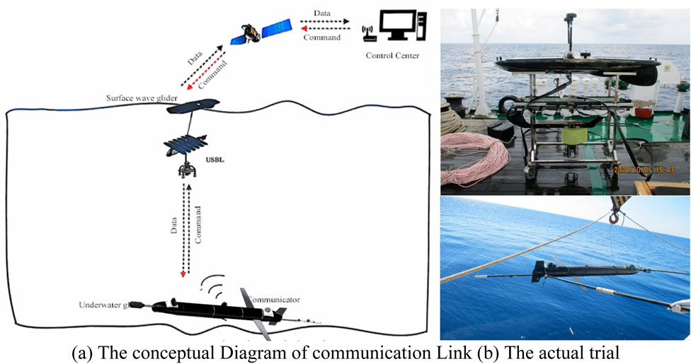
Figure 1. Communication link diagram. (A) The conceptual Diagram of communication link (B) The actual trial.
The hardware system includes three parts: surface wave gliders, underwater gliders, and signal processors mounted on them.
We have established a wave glider framework that includes an inertial frame, a surface vessel, and an underwater tractor. The wave glider consists of a surface ship and an underwater tractor. The water surface mother is 2.6 m long, 0.6 m wide, and 0.3 m high. It adopts EVA floating material polyurea spray structure to minimize its own weight while ensuring more buoyancy; Four solar panels are installed on the surface for system power supply, providing a total output power of 200 W. Flexible communication cables are mainly composed of multi-core armored cables and universal joints, with a length of 7 m and the ability to provide a load of 1 ton. The underwater tractor is 1.92 m long, 1.1 m wide, and 0.35 m high. It mainly utilizes wave energy to drive, with a maximum driving speed greater than 0.5 m per second. The focus of this study is on the underwater tractor frame, with a towed ultra short baseline (USBL) connected to the frame, measuring Ø 170 × 133 mm, consisting of one sensor and four hydrophones with a cross-array structure. The maximum sound source level of the transducer is 190 dB, the optimal frequency range is 10–15 kHz, and the receiving sensitivity of the hydrophone is −185 dB @ 1 V/µ Pa. Multiple methods have been adopted to reduce position errors, such as installing attitude sensors, optimizing the installation process, and using precise structural design (Stinco et al., 2019).
Acoustic undersea glider has a length of 2.6 m, a diameter of 0.23 m, an average speed of two knots, and a maximum diving depth of 1,000 m. The cockpit located at the front end of the glider is mainly used to install observation and detection sensors, including acoustic modules and CTD sensors. The acoustic module includes a sound vector sensor and a signal processing cabin. The size of the vector sensor is Ø 66 × 78 mm, with a sensitivity of 191.5 dB (0 dB re 1V/uPa), and the working bandwidth can be extended from 10Hz to 3 kHz. The acoustic signal processor is located inside the head compartment and is used to collect and store the output signals of the acoustic vector sensor.
The middle compartment is a pressurized compartment, divided into three compartments. The underwater acoustic communication signal processor is installed in the first cabin, together with a set of batteries and drive mechanisms, to form the attitude adjustment module. The second cabin is equipped with a navigation control module and a set of backup battery packs. The navigation control module needs to interact with the underwater acoustic communication signal processor for data exchange. An oil pump is installed in the third compartment, which changes buoyancy by injecting and extracting oil into the oil bag. A pair of carbon fiber wings are fixed on both sides of the third compartment for pitch attitude adjustment. The tail compartment is immersed in seawater, and two acoustic transducers installed in the tail compartment are inclined at a 30° angle to the vertical line of gravity. They are connected to the acoustic communication signal processor through a cable passing through the compartment for transmitting and receiving acoustic signals. Two transducers work alternately underwater, always keeping one transducer in a vertical upward position, ensuring that the energy amplitude and angle of the transducer do not fluctuate significantly after the attitude of the underwater glider changes. The oil bag is part of the buoyancy adjustment module, providing buoyancy for the glider to float up and down. The propeller and satellite communication antenna are placed at the very end of the aft compartment.
An underwater glider is an energy-saving propeller free unmanned aerial vehicle that can operate for months because it uses a battery powered hydraulic pump to change buoyancy, allowing it to glide forward along a zigzag trajectory. The underwater glider used in this article is a cylindrical body with a length of 2.6 m and a diameter of 0.23 m, provided by Tianjin University. It has a speed of two knots and a maximum depth of over 1 km. This is a very mature platform equipped with an acoustic modem operating in the 9–15 kHz range, with a maximum nominal range of 10 km and a speed of 200 bps, used for transmitting data between wave gliders.
Underwater gliders use half duplex communication to issue shore-based commands and transmit real-time observation data, requiring continuous reception and processing of underwater acoustic signals. However, uninterrupted data reception and communication can impose a significant burden on the glider’s battery. In addition, it is difficult and costly to replace batteries in underwater gliders, so reducing system power consumption is of great significance for extending the working time of underwater gliders. In addition, the limited internal space of underwater gliders also poses challenges to the design of signal processors. Taking into account power consumption and size, the size of the signal processor is 10.5 mm * 5.5 mm * 5.5 mm, which includes three main parts: receiving data conditioning, high-efficiency signal transmission, and low-power signal processing, as shown in Figure 2. Receiving data conditioning mainly completes functions such as amplification, filtering, and gain control. The high-efficiency signal transmission module includes a high-efficiency Class D power amplifier and a matching network, which enables the transmission of underwater acoustic signals with sound source levels greater than 186 dB. The low-power signal processing part specifically includes the on duty wake-up and high-speed DSP processor parts, which respectively perform low-power signal detection and communication positioning algorithms. The duty circuit is used to control the power supply of the system. When it is idle, the duty circuit works and monitors external signals; When the duty circuit detects the wake-up signal, it powers on the working circuit and wakes up the system, and the system enters the working state. Through this working mechanism, the system can receive signals and start working, while greatly reducing system consumption when no signal is received, effectively controlling energy consumption, and improving power utilization. The electronic module is connected to the glider carrier through a power cord and an RS-232 serial port cable.
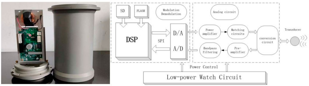
Figure 2. Signal processor.
The communication system includes two parts: the control and positioning function from the shore control platform to the underwater glider, and the information feedback function from the underwater glider to the shore control terminal. (1) Control and positioning function: The shore control platform sends positioning requests for underwater mobile nodes to the surface wave glider via satellite at regular intervals. After receiving the command, the surface glider forwards it to the surface USBL acoustic communication device through the serial port to complete the positioning of the underwater acoustic communication device with the specified ID. Subsequently, the position information of the underwater acoustic communication device will be sent back to the surface glider through the serial port. In addition, the shore control platform can also send control instructions to underwater mobile nodes based on multi-source information fusion. The surface glider sends these commands to the surface USBL acoustic communicator through a serial port, and then transmits the commands to the underwater acoustic communicator through underwater acoustic communication. Finally, the underwater acoustic communicator sends the commands to the glider controller through the serial port to complete the instruction issuance. (2) Information feedback function test: When the underwater warning glider detects the target and calculates the preliminary orientation, the main control system sends the information to the underwater acoustic communication device through the serial port. The dual transducers carried will switch between working according to the diving and surfacing status of the glider, ensuring that at least one transducer is always within the working range. After receiving the main control command, the underwater acoustic communicator sends data packets to the surface USBL acoustic communicator through underwater acoustic communication. During this process, the underwater acoustic transmitter will calculate its own position information and send the positioning information along with the underwater transmission data packet to the floating glider on the water surface through a serial port. Finally, it will be transmitted to the shore control platform via satellite, achieving a cross medium communication link from underwater to airborne platforms.
As shown in Figure 3, MFSK communication system algorithm was designed based on a signal processor. MFSK provides a compatible solution that combines stability and reliable quality, effectively overcoming issues related to multipath mobile platforms that are susceptible to Doppler frequency shift and require high signal-to-noise ratio (SNR) for reception (Rice and Green, 2008). Using cyclic prefix to reduce inter-symbol interference can successfully maintain an acceptable communication rate in the region without affecting stability, making it a particularly suitable choice for communication between heterogeneous gliders.

Figure 3. Process flowchart of MFSK modulation and demodulation.
After channel encoding the input bit stream, the transmitting end modulates it onto multiple subcarriers of a certain bandwidth using inverse Fourier transform and transmits it. This method has good anti-interference characteristics and is suitable for stable communication in complex channel environments. The processed waveform is prefixed with a cyclic prefix to counteract multipath between channels. And unlike traditional MFSK modulation, this system adds synchronization sequences and guard intervals to both the front-end and back-end of communication data. As shown in the data framework structure diagram 3, the selected synchronization signal is a linear frequency modulation signal (LFM), which exhibits good autocorrelation characteristics and is insensitive to the Doppler effect. Firstly, the input binary signal is added cyclic redundancy check (CRC) bits to detect errors at the receiving end. K-encoding means adding some redundancy, extending the information carried by a few bits to more bits, in order to enhance the anti-interference ability of the data. The interleaver can prevent sudden noise from interfering with single signal. Hadamard–On off keying–IFTT generates modulation waveforms suitable for channel transmission. This method is highly resistant to interference, Doppler, and multipath, making it suitable for stable communication in complex environments. Finally, cyclic prefix and LFM are added to avoid mutual interference between signals.
At the receiving end, the local synchronization signal is correlated with the received signal through a matched filter, and synchronization detection is performed by comparing the correlation peak with a predetermined threshold. After the same detection, the Doppler frequency offset factor is estimated by using the time interval between the two linear frequency modulation signals before and after. After Doppler compensation, the unquantized frequency energy information output by the demodulator is input into the joint decoder, and the soft decision value decoded by the Hadamard code is directly used as the branch measurement value of the Viterbi decoder. At the same time, Hadamard code soft decision and Viterbi soft decision decoding are implemented, and the decoded bit stream is output.
The data frame structure consists of frame synchronization, guard interval, single frequency signal, 9 MTSK symbols, and a fixed transmission of 9 MFSK symbols per data frame. Each MFSK symbol contains 6 Hadamard codes, each carrying 5 bits of information. Therefore, the number of encoded bits transmitted each time is 270. Using channel coding with a 1/2 bit rate, the number of bits per frame before coding is 135. After deducting CRC and padding zeros, the total number of effective data bits that can be transmitted in k frames is n = 135 * k-21.
In order to verify the communication performance of acoustic underwater gliders, a surface wave energy glider integrated with underwater acoustic communication aircraft is selected as a surface relay to carry out a one-on-one communication test in the South China Sea in 2024, with a depth of about 1800 m in the test area. Surface wave energy gliders move with the waves on the surface of the water, and underwater gliders do profile gliding underwater at a speed of about 1kn/s. Control the maximum diving depth of 850 m, control the glider in the water depth of 5 m, 50 m, 100 m, 200 m, 300 m, 400 m, 500 m, 600 m, 700 m, 800 m trigger the underwater acoustic communication machine to communicate with the surface end.
The depth of the South China Sea was 2 km on that day, and the sound velocity gradient was standard deep ocean sound velocity gradient. After processing the test data, the original time-frequency domain waveform diagram stored by the underwater glider when communicating at a certain depth and oblique distance is obtained (Figures 4A, B).
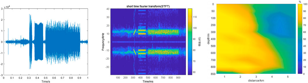
Figure 4. Time domain and frequency domain waveforms and Communication success rate at different distances. (A) The time-domain waveform (B) The frequency-domain waveform (C) Communication success rate.
Gliders use ultra short baselines to locate their underwater position during different ascent or descent processes. After determining the location, underwater acoustic communication at different depths and distances will be carried out, and the number of successful communications will be counted. The original time-frequency waveforms stored by underwater gliders during communication at different depths and at different oblique distances are analyzed, and the success rate of communication at different distances is obtained in Figure 4C. Y-axis represents the diving depth of the underwater glider, and X-axis represents the communication distance. It can be seen that within the entire range of 3 km, the success rate of almost the entire depth is 80%. With the increase of distance, the success rate of communication in the depth of shallow water layer gradually decreases. At 700 m and 800 m depth, the success rate of 70% is also consistent with the deep-sea propagation law, and the success rate of unstable communication of the platform decreases due to the platform itself turning over and shaking at the depth of 850 m.
In this paper, an underwater acoustic communication system based on unmanned platforms is designed to facilitate the exchange of information between these platforms. The problems of real-time data transmission of underwater mobile nodes and cooperative formation control observation are effectively solved. The dual transducer design ensures that the energy amplitude Angle of the transducer does not fluctuate greatly after the attitude change of the underwater glider, and the multi-carrier frequency shift keying underwater acoustic communication technology improves the communication stability. Through sea trials, the acoustic underwater glider achieved the ability to communicate over a distance of more than 5 km and a communication success rate of more than 80%. The research results of this paper can provide a basis for the cross-media communication between heterogeneous underwater UUV, underwater, surface, space-based and shore-based platforms, and the proposed system is suitable for long-term ocean observation.
The data analyzed in this study is subject to the following licenses/restrictions: The data in this article is subject to confidentiality restrictions and cannot be made public. Requests to access these datasets should be directed to BaohengLiu, YmFvaGVuZ2xpdUAxNjMuY29t.
SJ: Methodology, Resources, Writing–original draft. BL: Software, Writing–original draft. SZ: Formal Analysis, Investigation, Writing–review and editing. XZ: Writing–review and editing.
The author(s) declare that financial support was received for the research, authorship, and/or publication of this article. This work was supported by National Key R&D Program of China under Grant No. 2021YFC3100900 and Qingdao Institute of Collaborative Innovation under Grant No. LYY-2022-04.
The authors declare that the research was conducted in the absence of any commercial or financial relationships that could be construed as a potential conflict of interest.
The author(s) declare that no Generative AI was used in the creation of this manuscript.
All claims expressed in this article are solely those of the authors and do not necessarily represent those of their affiliated organizations, or those of the publisher, the editors and the reviewers. Any product that may be evaluated in this article, or claim that may be made by its manufacturer, is not guaranteed or endorsed by the publisher.
Lan, H., Lv, Y., Jin, J., Li, J., Sun, D., and Yang, Z. (2020). Acoustical observation with multiple wave gliders for internet of underwater things. Internet Things J. 8, 2814–2825. doi:10.1109/JIOT.2020.3020862
Li, S., Wang, Y. H., Wu, S., Niu, W., Yang, S., and Lan, S. (2022). Multi-body modelling and analysis of the motion platform for underwater acoustic dynamic communication. Appl. Math. Model. 109, 455–472. doi:10.1016/j.apm.2022.05.005
Li, X., Zhu, M., and Wu, Y. (2015). Low-power system design for underwater acoustic modems. ACM, 1–2. doi:10.1145/2831296.2831307
Magistris, G. D., Uney, M., and Stinco, P. (2020). Selective information transmission using convolutional neural networks for cooperative underwater surveillance. ISIF Fusion. doi:10.23919/FUSION45008.2020.9190461
Mantouka, A. P., Felisberto, P., Santos, P., Zabel, F., Saleiro, M., Jesus, S., et al. (2017). Development and testing of a dual accelerometer vector sensor for AUV acoustic surveys. Sensors 17 (6), 1328. doi:10.3390/s17061328
Marques, E., Pinto, M., and Kragelund, S. (2007). “AUV control and communication using underwater acoustic networks,” in Oceans. IEEE.
Petroccia, R., Sliwka, J., and Grati, A. (2018). “Deployment of a persistent underwater acoustic sensor network: the CommsNet17 experience,” in 2018 oceans - MTS/IEEE kobe techno-ocean (OTO) (IEEE). doi:10.1109/OCEANSKOBE.2018.8559262
Qiao, G., Zhao, Y., Liu, S., and Bilal, M. (2017). Dolphin sounds-inspired covert underwater acoustic communication and micro-modem. Sensors 17 (11), 2447. doi:10.3390/s17112447
Rice, J., and Green, D. (2008). “Underwater acoustic communications and Networks for the US Navy’s Seaweb program,” in International conference on sensor technologies and applications (IEEE). doi:10.1109/SENSORCOMM.2008.137
Seto, M., Saeedi, S., and Li, H. (2014). AUV navigation and localization: a review. IEEE J. Ocean. Eng. A J. Devoted Appl. Electr. Electron. Eng. Ocean. Environ. 39, 131–149. doi:10.1109/joe.2013.2278891
Soldi, G., Gaglione, D., and Magistris, G. D. (2020). “Underwater tracking based on the sum-product algorithm enhanced by a neural network detections classifier,” in IEEE international conference on acoustics. Speech and signal processing. doi:10.1109/icassp40776.2020.9054038
Stinco, P., Tesei, A., and Biagini, S. (2019). “Source localization using an acoustic vector sensor hosted on a buoyancy glider,” in Oceans 2019 - marseille (IEEE). doi:10.1109/OCEANSE.2019.8867452
Stinco, P., Tesei, A., Ferri, G., Biagini, S., Micheli, M., Garau, B., et al. (2021). Passive acoustic signal processing at low frequency with a 3-D acoustic vector sensor hosted on a buoyancy glider. IEEE J. Ocean. Eng. 46 (1), 283–293. doi:10.1109/JOE.2020.2968806
Sun, Q., and Zhou, H. (2022). An acoustic sea glider for deep-sea noise profiling using an acoustic vector sensor. Marit. Res. 29 (113), 57–62. doi:10.2478/pomr-2022-0006
Tian, D., Zhang, X., Zou, S., Sun, Q., and Da, L. (2023). Experimental application of heterogeneous gliders communication system in South China Sea. Ocean. Eng. 289 (1), 116187. doi:10.1016/j.oceaneng.2023.116187
Keywords: surface wave glider, underwater glider, communication system, hardware system architecture, communication system algorithm
Citation: Jia S, Liu B, Zou S and Zhang X (2025) Experimental application of gliders communication system in South China Sea. Front. Commun. Netw. 6:1529690. doi: 10.3389/frcmn.2025.1529690
Received: 17 November 2024; Accepted: 14 January 2025;
Published: 10 February 2025.
Edited by:
Rosdiadee Nordin, Sunway University, MalaysiaReviewed by:
Nor Fadzilah Abdullah, Universiti Kebangsaan Malaysia, MalaysiaCopyright © 2025 Jia, Liu, Zou and Zhang. This is an open-access article distributed under the terms of the Creative Commons Attribution License (CC BY). The use, distribution or reproduction in other forums is permitted, provided the original author(s) and the copyright owner(s) are credited and that the original publication in this journal is cited, in accordance with accepted academic practice. No use, distribution or reproduction is permitted which does not comply with these terms.
*Correspondence: Baoheng Liu, YmFvaGVuZ2xpdTIwMjRAMTYzLmNvbQ==
Disclaimer: All claims expressed in this article are solely those of the authors and do not necessarily represent those of their affiliated organizations, or those of the publisher, the editors and the reviewers. Any product that may be evaluated in this article or claim that may be made by its manufacturer is not guaranteed or endorsed by the publisher.
Research integrity at Frontiers
Learn more about the work of our research integrity team to safeguard the quality of each article we publish.