- 1Advanced Wireless Technology, Dell Technologies, Ottawa, ON, Canada
- 2Advanced Wireless Technology, Dell Technologies, Toronto, ON, Canada
- 3Telecom Systems Business Unit, Dell Technologies, New Cairo, EG, Egypt
- 4Advanced Wireless Technology, Dell Technologies, Montreal, QC, Canada
- 5Telecom Systems Business Unit, Dell Technologies, Ottawa, ON, Canada
Open radio access network (O-RAN), driven by O-RAN Alliance is based on the disaggregation of the traditional RAN systems into radio unit (RU), distributed unit (DU) and central unit (CU) components. It provides a unique opportunity to reduce the cost of wireless network deployment by using open-source software, serving as a foundation for O-RAN compliant functions, and by utilizing low-cost, generic white-box hardware for radio components. Relying on the two core pillars of openness and intelligence, there has been a coordinated global effort from operators and equipment providers to enhance the RAN architecture and improve its performance through virtualized network elements and open interfaces that incorporate intelligence in RAN. With the increased complexity of 5G networks and the demand to fulfill requirements, intelligence is becoming a key factor for automated deployment, operation, and optimization of open wireless networks. The first thrust of this paper surveys the AI/ML architecture in O-RAN specifications, key discussion points and future standardization directions, respectively. In the second part, we introduce a proof-of-concept use case on AI-driven network optimization within the near real-time RAN intelligent controller (near-RT RIC) and non-real time RIC (non-RT RIC). In particular, we investigate the user admission control problem, led by a deep learning-based algorithm, implemented as an xApp for network performance enhancement. Extensive system-level simulations are performed with NS-3 LTE to assess the proposed admission control algorithm. Accordingly, the proposed dynamic algorithm shows a significant admission control performance improvement and flexibility, compared to existing admission control static techniques, while satisfying the stringent quality of service targets of admitted devices. Finally, the paper offers insightful conclusions and findings on the AI-based modeling, model inference performance, key performance challenges and future research directions, respectively.
1 Introduction
The fifth generation (5G) and beyond cellular networks are envisioned to support multiple quality of service (QoS) classes which demand a diverse and wide set of radio performance targets such as broadband data rates, stringent radio latency, strict link reliability, advanced processing, and computing power, respectively. However, current single-vendor network deployments, with proprietary interfaces and equipment, highly restrict the cellular technology innovation, progression, and capability to support future critical use cases. Thus, Open Radio Access Network (O-RAN) has introduced new interfaces and architectures relying on openness and interoperability that support enabling programmable data-driven control and intelligence in network deployments (Bonati et al., 2020). Openness allows operators to choose different open off-the-shelf hardware and software components from multiple suppliers without being restricted to a single-vendor proprietary hardware, and accordingly, build flexible and on-demand scalable RAN deployments. Still, there are currently multiple challenges in multi-vendor deployment model such as: (1) added complexity to identify and isolate unwanted performance issues in the network, herein, the role of the system integrator becomes vital for managing and controlling the added troubleshooting complexity, and (2) security is a particular area of concern as the infrastructures deployed by different vendors’ equipment could increase threat surface areas. Therefore, there has been a coordinated global effort to improve O-RAN architecture performance through virtualized network elements and open interfaces that incorporate intelligence over RAN and to leverage emerging learning methods to employ intelligence in every layer of the RAN architecture.
AI/ML techniques have been developed since the 1950s to resolve multiple research problems, which are highly challenging to optimize in a manual setting, from vision applications to expert systems. In parallel, the complexity of wireless technology has significantly grown, i.e., multi-RAT heterogeneous networks, facing challenging requirements in terms of throughput, latency, and reliability (Wang et al., 2020; Kaur et al., 2021). Thus, it is a natural evolution for the wireless community to evaluate how AI/ML solutions can support design and deployment constraints faced by next-generation wireless systems (from compensation of RF non-linearities to end-to-end network optimization and automation). However, it is not a straightforward task to apply AI/ML solutions in the wireless domain due to several unique performance challenges. For instance, (a) in partially observable deployments, the decision algorithms have only a partial view of the network, which results in a sub-optimal AI/ML operation, (b) non-stationarity, where the propagation conditions, user locations and traffic characteristics may all rapidly evolve, (c) real-time constraints, e.g., L1/L2 applications running at millisecond timescales, (d) low-data regime, where it can be difficult in certain deployments to obtain a high number of samples for some network/environment conditions, which rarely occur, and (e) scalability challenges, where the AI/ML decisions may be applied to thousands of user equipment’s (UEs) or even more within wide-scale industrial internet of things (IIOTs) deployments (Voss, 2022).
In addition, an AI multi-agent strategy is required when multiple AI processes run in parallel and apply independent actions on the same network parameters and/or the same network area. Those agents are cooperative by design; however, some competition may also occur, e.g., in case of jamming or a security attack or when the impact of a decision on adjacent network parameters is not well controlled. The O-RAN architecture enables this multi-layer decision-making architecture. For instance, a UE may perform intelligent sensing on its environment while intelligence at the RU level may optimize the beam-forming patterns. The DU cognitive module may perform scheduling decisions on sub-millisecond basis (Polese, et al., 2020) while the near-RT RIC decides user association on multiple cells (e.g., resource optimization) and a non-RT RIC enhances the long-term network performance (e.g., policy selection and network orchestration) by aggregating data on a larger network area. In parallel, the amount of storage and processing capabilities required for each of those intelligent modules may be dynamically adapted through proper network function orchestration, and according to the deployment-specific requirements. The O-RAN disaggregated architecture enables to benefit from a large pooling effect multiplied by the progress made on state-of-the-art server architectures (Dell Technologies, 2022).
The demand in the number of wireless UEs and their rigorous performance targets make optimizing the network capacity a highly challenging task. Therefore, to utilize the wireless resources efficiently while serving a guaranteed QoS profile for each UE, the network seeks to find the maximum number of UEs that can be supported simultaneously (Manosha et al., 2017). This operation is called ‘user Admission Control (AC)’, where the network determines and is able to admit a number of UEs for which their QoS targets are likely to be satisfied, e.g., their target data rates are fulfilled (Caballero et al., 2018). User AC is considered an optimization problem where the conventional exhaustive search approach is one method to find the global optimal solution. However, by increasing the number of users, the computational complexity of this method increases exponentially, and some suboptimal algorithms are looked for in practical scenarios (Nguyen et al., 2015). The user AC problems have been extensively studied in open literature. AC has been first examined in relation to Single-Input Single-Output (SISO) systems in (Liu et al., 2012) wherein an l0 problem has been cast. Different priority user groups are taken into account in (Monemi et al., 2015), and an iterative algorithm is proposed by taking use of the correlation between the Signal-to-Interference-plus-Noise Ratio (SINR) and the transmit power of users. Centralized algorithms are also proposed to tackle the user AC optimization problem (Nguyen et al., 2015); d. The centralized implementation has been investigated for Multiple-Input Single-Output (MISO) systems (Matskani et al., 2008) wherein it has been defined as an integer non-linear optimization problem for a single cell. Then, using the semidefinite relaxation method, two approximations of solutions are developed. A distributed algorithm has also been proposed in (Mitliagkas et al., 2011) utilizing the dual decomposition method. Resource access schemes have also been a subject of investigation for 5G specific use cases (Qiu et al., 2020), for instance using blockchain to determine the admission and resource access for IoT based networks (Ding et al., 2019). In addition to higher data rates provisioning, there are other distinct use cases in 5G, namely ultra-reliable low latency communications (URLLC), and massive machine type communication (mMTC). Each use case provides distinct challenges for the admission control problem, and also dependencies on different network parameters as shown by recent works in literature (Mehmeti and La Porta, 2019; Mehmeti and La Porta, 2021a; Mehmeti and La Porta, 2021b).
Furthermore, in cellular networks, users may experience widely different radio conditions. For instance, users, who are closer the base station (BS), have a higher average SINR than users that are at the cell edge. Furthermore, certain users may be located in a rich scattering environment while others may not experience similar conditions (Tse and Vishwanath, 2005). Therefore, it is challenging to ensure fairness among users while they are being dynamically admitted to the system because of the varying fading statistics (Manosha et al., 2017). The majority of the currently adopted AC algorithms consider a static mobility deployment or utilizing AC algorithms for a certain instance, while in some newer problem, mobile scenarios are taken into consideration. Some implementations also perform AC for all UEs simultaneously, assuming all connection requests are received at the same time. Therefore, when such solutions are used over time in a dynamic network, they might not offer fairness when admitting users. Consequently, there has to be concrete research to leverage emerging learning methods for this challenge.
In this paper, we first present the key Open RAN technology architecture, following O-RAN Alliance standardization, interoperability opportunities, and its potential for enabling true artificial intelligence based cellular solutions. We survey the background of the O-RAN Alliance reference architecture and describe its vision and its workgroups structure. In the following section, we consider a practical deployment use case on the problem of single cell user AC with dynamic traffic. Assuming sequential (and irregular) UE activity, performing dynamic AC in an online setting is essential. Accordingly, we present a proof of concept, intended for a cell-level AC use case which is integrated within a network-simulator-3 (NS-3) framework, and complemented by an advanced AI/ML AC learning solution.
2 Overview on O-RAN alliance architecture, interfaces, and standardization
2.1 O-RAN alliance architecture
Open RAN, driven by O-RAN Alliance (as one of the dominant open RAN standard organizations), is based on the disaggregation of the traditional RAN systems into radio unit (RU), distributed unit (DU) and central unit (CU) components, in addition to various hardware platforms and software. Open RAN is a transformation of the existing mobile networks; it brings a diverse ecosystem into the development of RAN infrastructures, instead of the traditional vendor-proprietary solutions. It allows operators to choose different hardware and software components from multiple suppliers without being restricted to one telecom vendor. We should highlight that Open RAN technology started as a movement that applies to all mobile technology generations (all xGs), i.e., 2G, 3G, 4G, 5G, and all future Gs. On top of 3GPP defined specifications, O-RAN Alliance also specifies Open RAN internal interfaces between the key RAN building blocks which ensure multi-vendor interoperability. While Open RAN technology is fully compliant with the 3GPP standards, it further evolves the RAN capabilities towards truly open and intelligent RAN systems, offering the following key enablers (2020 5G America, 2020):
− Open standardized interfaces between RUs and baseband units (BUs), including the element management system (EMS) of the radio/baseband, the network management system, control and data planes, and the CU and the DU, respectively.
− Decoupling the deployed software from the hardware platforms executing it.
− Open hardware that offers platforms with general purpose processors and accelerators.
− Open software that is commercially viable to meet all the high performing critical performance requirements to support real-time system specifications.
Particularly, for Open RAN networks, evolving the standardization of the interfaces and ensuring interoperability of the disaggregated components are the keys to success and mass adoption. 3GPP partners have studied, and accordingly specified, different functional split options between the CU and DU, which go from the high layer RAN split to the low layer split, as shown in Figure 1. Before selecting a potential function split for a certain Open RAN deployment, several aspects need to be considered as follows:
− Transport Bandwidth: Referring to Figure 1, the transport bandwidth, i.e., required data rate, is decreased, while the achievable latency increases with the split option from the left to the right, i.e., from split option 8 to split option 1. The selected functional split allows a tradeoff between flexibility and latency with requirements on the achievable data rate.
− Architectural function split: The architectural function split for Open RAN should be based on vendor neutral hardware and software. The O-RAN Alliance has designed an Open RAN interface set and defined radio hardware requirements with processing functions and capabilities under control of the DU and corresponding software.
− Interoperability: Interoperability between different vendor systems is an essential requirement for Open RAN systems. Thus, the architectural function split will result in an interface that can be easily implemented by any integrator and be rigorously tested to allow for such interoperability.
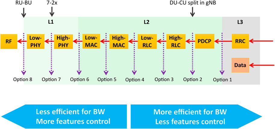
FIGURE 1. Function split options between CU and DU for DL Reproduced with permission from 3GPP (2017).
As a result, after evaluating different RU, DU, and CU split options specified by the 3GPP and compromising among complexity, flexibility, transport data rate, latency, performance, and overall costs associated with each split, the O-RAN Alliance has accordingly defined the architecture and interfaces as double function splits with option 2 (DU-CU split/high layer split) and option 7-2x (DU-RU split/low layer split). For small cell scenarios, Small Cell Forum (SCF) has standardized option 6 (MAC-PHY split) interface associated with user, control, synchronization, and management planes as well. In this paper, we mainly focus on O-RAN defined architecture with option 2 and option 7-2x as depicted in Figure 2.
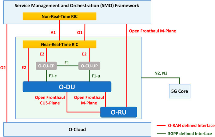
FIGURE 2. O-RAN data flows and Reproduced with permission from O-RAN Working Group 4 (2022).
As a high layer split, the important benefit to have split option 2 is that all central unit (CU) functions can be fully virtualized and running on servers in qualified data centers. With split option 2, the user plane (U-plane) and control plane (C-plane) are separated as well. Based on 3GPP function splits options 2 and 7-2x, the O-RAN architecture shall include a service management and orchestration (SMO) platform, RAN intelligent controllers (RICs) for near real-time (near-RT) and non-real-time (non-RT) decisions (which will be detailed in Section 2.3), and O-RAN functions. Furthermore, the O-RAN Alliance has standardized their own interfaces for the Open RAN architectures and extended the existing 3GPP interfaces and eCPRI as fronthaul to connect O-DU and O-RU.
2.2 O-RAN alliance interfaces
Besides the similar planes defined by 3GPP with U-plane/C-plane, with the new function split and the data traffic flow in Open RAN architecture, O-RAN Alliance has also defined the M-plane for handling management and configuration, the S-plane for handling synchronization and timing and extended C-plane for handling near real time control. As depicted by Figure 2, the O-RAN Alliance defined interfaces that connect the Network Function (NF) building blocks of the O-RAN architecture, including O1, O2, A1, E2 for upper layer split as described below (other interfaces such as R1 within between SMO and rApps is out of scope of this paper). For lower layer split, the existing interface eCPRI as a front-haul connects the O-DU and O-RU.
− O1 interface: this interface supports the management entities within the SMO framework and includes the O-RAN managed elements such as the operation and maintenance (OAM), related to function of multi-vendor including FCAPS (fault, configuration, accounting, performance management, security management), and software management, respectively.
− O2 Interface: this interface connects the SMO to the ORAN O-Cloud, and accordingly, it regulates a collection of services into two logical groups: the infrastructure management services, which is a subset of the O2 functions that are aimed for deploying and managing cloud infrastructure, and the deployment management services, which is the subset of O2 functions that are responsible for life cycle management of deployments on the cloud infrastructure.
− A1 Interface: this interface is defined between the non-RT RIC (or SMO) and near-RT RIC. The non-RT RIC provides the near-RT RIC with operational guidance such as policies, for instance, to manage the adopted machine-learning (ML) model in xApps. It also governs the orchestration and automation (including the non-RT RIC), and 5G gNB (including the near-RT RIC).
− E2 Interface: E2 interface is an open interface for forwarding the measurements from the so-called E2-nodes, i.e., DUs, CUs, and O-RAN compliant LTE eNBs, to the near-RT RIC, and the configuration commands back to the DUs and CUs (Polese et al., 2022). This enables the network to control ongoing operations within the base station, using the supported monitor, suspend, control and override messages, run commands sent by the xApps, and the received data collection and metrics from those units.
In addition, as the fronthaul interface, the eCPRI enables the splitting of the baseband functions to reduce the traffic transfers and can be framed as a packetized interface within Ethernet to take advantage of the already-present ubiquitous Ethernet networks. As shown in Figure 3, with the split option 7-2x for DL, the Open RAN fronthaul interface connects the O-DU to one or multiple O-RUs. The physical layer functions are split into the lower part, i.e., PHY-low (L1-low) and the higher part, i.e., PHY-high (L1-high). The PHY-low resides in the O-RU to perform I/Q decomposition, precoding, digital/analog beamforming, inverse Fast Fourier Transform (iFFT) and cyclic prefix (CP) addition. The PHY-high resides in the O-DU to perform the scrambling, modulation, layer mapping, precoding, resource element mapping, and I/Q compression.
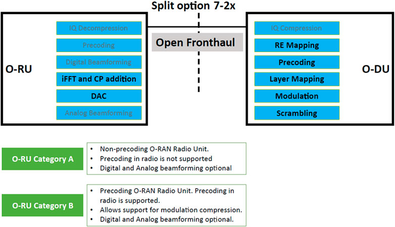
FIGURE 3. Open RAN architecture split option 7-2x for DL. Processing blocks, with a bold text, are mandatory for all O-RU categories. Precoding operation for certain O-RU categories can be executed within the O-RU, where the precoding in O-DU can be Reproduced with permission from O-RAN Working Group 4 (2022).
Additionally, the O-RAN Alliance distinguishes the 7-2x split between Category A and Category B type O-RUs, depending on if O-RU supports precoding function, as shown in Figure 3. The Category B type O-RU supports multi-antenna systems for massive MIMO, while Category A O-RU supports remote radio heads (RRHs) with 1/2/4Tx/Rx. The details of O-RAN DL and UL structure and design of split 7-2x are presented in O-RAN Alliance technical specification (Rouwet, 2022).
2.3 RAN SMO and RIC proposed by O-RAN alliance
In this Section, we briefly explain the details of the upper layer split with non-RT and near-RT RICs. In order to enable programmability of the RAN through the RIC, the O-RAN Alliance’s objective is to separate the control and management functions of the RAN infrastructure from its data plane functions. To enable a more optimized ecosystem of intelligent features and applications located close to the edge of the RAN, the hierarchical non-RT and near-RT with the A1, O1, and E2 interfaces are proposed in the O-RAN Alliance’s reference architecture. O-RAN reference design introduces a hierarchical RIC platform that makes use of the computing capabilities of a cloud-native environment to enable AI/ML driven intelligent decisions and RAN automation. Figure 2 depicts the general organization of hierarchical control loops employing various O-RAN functions (O-RAN Working Group 1, 2021). Non-RT functions, referred as rApps, include service, configuration, policy management, and RAN analytics. The non-RT RIC hosts model-training for the near-RT applications in some cases. For these cases, the trained models and real-time control functions generated in the non-RT RIC are transferred to the near-RT RIC for runtime execution. To encourage creativity and openness, the near-RT RIC is introduced as an open compute edge platform hosting multi-vendor applications. Additional open interfaces are added when a new compute platform is added into the reference architecture (Polese et al., 2022). provides a comprehensive discussion regarding open interfaces. The xApps, or third-party applications, that are deployed onto near-RT RIC, are mainly trained ML models that operate in a cloud-based setting close to the edge of RAN and provide near-RT control commands to CU/DU.
The split RICs based on the latency tolerance of the associated micro-services is a new NF introduced by O-RAN Alliance. Non-RT RIC supports rAPPs facing operators such as fault management, performance management, and lifecycle management, respectively, involving control loops of 1 s or more; near-RT RIC supports xApps facing radio infrastructure such as radio resource management, interference detection and mitigation, respectively, involving control loops of 10 milliseconds up to 1 s (O-RAN Working Group 6, 2020). Together, they are responsible for RAN operation and optimization procedures across multi-operator services and multi-vendor’s hardware and software components. This timing-based split allows non-RT RIC to perform compute-heavy and storage-heavy AI/ML model training, e.g., to discover and predict statistical patterns such as the network spatio-temporal traffic patterns, user mobility patterns, massive MIMO parameters configuration patterns based on counters, statistics, fault alarms collected by SMO. Accordingly, they provide policy-based guidance to near-RT RIC for run-time execution to achieve efficient radio resource allocation. The ML model inference and/or retraining at locations closer to the distributed O-RU consume much less compute and storage. To further improve interoperability, the near-RT RIC is backward compatible with legacy radio resource management through the E2 interface, inviting both new and traditional vendors to join the O-RAN innovation to develop best ways of bundling functional blocks to achieve the maximum efficiency and optimal latency according to the deployment scenarios, e.g., macro, massive MIMO, and small cell deployments, respectively (Polese et al., 2022).
2.4 O-RAN alliance standardization and use cases
2.4.1 3GPP movement on standardization openness
3GPP has first started development of various functional split options as part of Release-14 (2014, TR 38.801), i.e., pre-5G release. The introduced functional splits aimed at introducing the notion of disaggregating the standard protocol stack, such as to separate processing a certain layer of the protocol stack from the computing entity. Such 3GPP movement is considered the initial seed for true cellular interface and processing openness and has been the key driver for subsequent O-RAN specifications. Furthermore, as the 3GPP release-18 progresses (i.e., 2023—5G-advanced), new critical use-cases are emerging such as extended reality (XR). Those emerging service classes require extensive computing powers (which is typically delegated to the edge of the network, i.e., edge computing), high-capacity, and low latency radio links, respectively. Accordingly, the efficient support of those stringent services is highly challenging. It is therefore envisioned that future O-RAN architectures may upgrade the cellular systems’ capability to efficiently support those future use-cases, due to, unlike 3GPP native systems, its unique computing pooling capabilities, and ultimate interface flexibility.
There are several industry-led open RAN initiatives that seek to unite an ecosystem of supply chain partners and advance open RAN through the definition, development, and testing of standards and reference architectures. Beyond the standards defined by the third Generation Partnership Project (3GPP), multiple industry groups are leading the open RAN movement, each with a different purpose as detailed in the following sub-sections.
2.4.2 O-RAN alliance, TIP, open RAN Policy Coalition and ONF
Because hardware, software and telecom companies work together to create an open virtualized cloud network, standardization is critical. There are a few predominant standardization organizations in the open RAN movement. However, there are only two that have attracted global media and more industrial attention than others: the O-RAN Alliance, formed in early 2018, a worldwide carrier-led effort that seeks to define new radio architectures, and the Telecom Infra Project (TIP), which was launched by Facebook (
Compared to the 3GPP standard interfaces and architecture, the O-RAN alliance focuses on a disaggregated and fully interoperable RAN architecture. Regarding RAN interface standardization, 3GPP mainly develops the interface between the UE and the network node, which is the eNodeB in long-term evolution (LTE) or the gNodeB in 3GPP New Radio technology (NR) and the inter-node interfaces. The network node, the eNodeB or gNodeB, has several layers of the 3GPP protocol stacks; however, it has been considered as a monolithic network entity that provides all the radio access services.
The node has components such as the RU and the DU, which are vendor-specific and inter-connected over proprietary interfaces so that wireless network operators must purchase a whole entity from a single vendor. O-RAN, however, pursues a goal to have a fully operational and interoperable architecture for RAN, with hardware and software from different vendors. O-RAN provides an architecture as a foundation of the virtualized and disaggregated RAN on open hardware and cloud. O-RAN specifications define the interoperable interfaces which fully support the O-RAN open architecture and complement the 3GPP standards.
It is important to emphasize the difference between TIP and O-RAN Alliance. O-RAN Alliance is involved in developing, driving and enforcing standards to ensure that components and equipment from different vendors interoperate with each other. To deploy an open and interoperable ecosystem, existing gaps in 3GPP and other standard bodies need to be addressed properly. It also creates profiles for interoperability testing where standards are available. On the other hand, TIP focuses mostly on deployment and execution. It supports Plugfests and live deployments in the field and ensures different vendor’s software and hardware equipment works with each other. This will enable supplier diversity and reduce deployment and maintenance costs across access, transport, and core networks, respectively.
Other two prominent industry-led open initiatives include Open RAN Policy Coalition and Open Networking Foundation (ONF). The first one was launched in mid-2020, and advocates policies to help drive open RAN adoption. Its growing membership includes telecom operators, equipment manufacturers, software developers, and silicon chip makers (Moniem Tech, 2021). ONF also announced several new initiatives in the open RAN domain in August 2020. This foundation is looking to deliver open-source implementations of functionality employed by open RAN components such as O-CU, O-DU, and RICs. From a technical perspective, the O-RAN Alliance’s work is the most foundational, prompting partnerships with many other organizations. It is in the midst of taking a new approach to the RAN market, in order to accelerate the adoption of its specifications. It will continue to work closely with other related standards organizations.
2.4.3 O-RAN alliance standardization timeline
The evaluated Open RAN solutions are generally related to 3GPP standardization activity, i.e., the future open networks are perceived as enhanced 4G/LTE and 5G/NR Radio Access Technologies (RATs) with new functions, logical blocks and vendor-agnostic platforms. Therefore, a vital open reference architecture—so called: O-RAN—is developed by O-RAN Alliance, and founded by AT&T, China Mobile, Deutsche Telekom, NTT DOCOMO and Orange in August 2018 (O-RAN Alliance, 2018). O-RAN Alliance is established as a fusion of two former organizations, C-RAN Alliance and xRAN Forum (Business wire, 2018). Those two organizations had different origins, i.e., China from one side and the United States, Europe, Japan and Korea from the other side. To date, O-RAN Alliance has been signing, developing, and publishing technology liaisons, collaboration agreements, and formal specifications (see Figure 4).
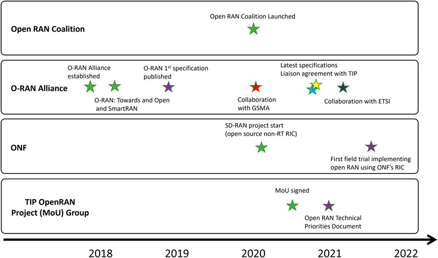
FIGURE 4. Timeline of selected actions and events related to Open RAN development Reproduced under CC-BY-4.0 from Wypiór et al. (2022).
2.4.4 O-RAN phase I and phase II use cases
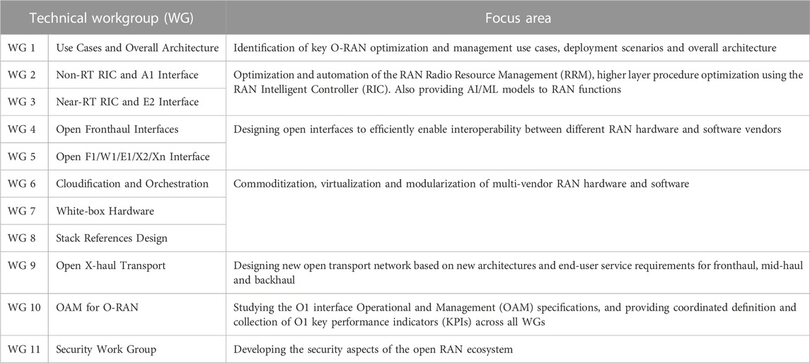
Figure 5 shows the different use cases defined by O-RAN Alliance and which are split into two phases as per organization members’ preference (Dryjański and Kliks, 2021). Use cases from Phase I shall be developed earlier to solve the more immediate needs of the operators (O-RAN Alliance, 2020). Similar to 3GPP stage-1/2 and stage-3 specification phases, O-RAN specifications follow a two-phase specification structure in order to first, during phase-1, study and specify high-priority and system-wide topics including white box hardware, traffic steering, QoS optimization, and massive MIMO, respectively. During phase-2, use-case specific and detailed specifications are performed, similar to 3GPP stage-3 detailed specifications, Herein, the specific system enhancements, including the new signaling procedures, new interface designs or capabilities, and message compositions, are all standardized, for enabling support of the target capabilities or services (which are identified during phase-1).
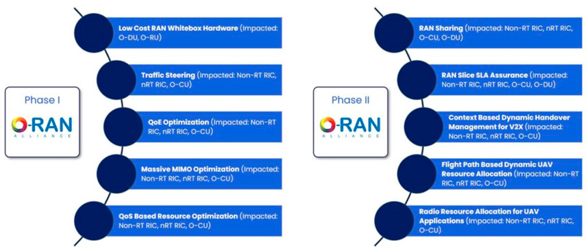
FIGURE 5. O-RAN use case phases and specification support Adapted from Rimedo Labs (2021), with permission from Rimedo Labs.
In the following section, we illustrate this new O-RAN intelligence architecture by presenting an AC proof-of-concept (PoC) use-case. For the reader’s convenience, we first survey the basic operation of AC in cellular systems.
3 AI/ML admission control use case
3.1 Motivation
Wireless networks operate on the principle of sharing available time and frequency resources among multiple users. Without any control on the number of UEs admitted to a cell, the perceived quality of service (QoS) of the users deteriorates as the number of UEs served by a cell increase, and likely the cell shall transition into a congested state. Cell AC in LTE and 5G is an effective method to mitigate this network congestion scenario and to ensure guaranteed QoS to the UEs. A call admission algorithm works on some preset rules or thresholds and provides a decision whether an incoming call can be accepted in the network, or whether it needs to be dropped. Accordingly, AC is an important radio resource management (RRM) technique used in both instances of new call setups and handoff calls within the network. Another purpose of AC is that it ensures the satisfaction of the different QoS targets for admitted users that demand different radio performance requirements based on the active service type, user preference, and network load (Skehil et al., 2007).
While operators may set counters at the radio resource control (RRC) layer, to control the maximum number of users in a cell with a fixed threshold, such static AC does not efficiently cater to variations in network traffic volume/arrivals, heterogeneous device types, and the different QoS profile requirements for requested 5G service classes such as the enhanced mobile broadband (eMBB), and ultra-reliable low-latency communications (URLLC), respectively. The 3GPP has also investigated, through different use case studies, the process and criteria for setting the maximum number of UEs that can use a network slice simultaneously (3GPP, 2021).
Employing methods from AI/ML domain to the AC problem in wireless networks has the potential to enhance efficiency in the decision-making process. Deep learning-based AC techniques have been shown to outperform non-AI based service grant and preference techniques in cloud and edge-based networking (Zhou et al., 2021). In the context of AI/ML based AC implementation within the O-RAN framework, multiple design aspects need to be addressed, as:
a. The flow of data collection from the E2 nodes using the O-RAN interfaces, this includes the type and granularity of performance metrics used for real-time inference and AI/ML model retraining
b. The AI/ML model types and/or categorizations which are most efficient for this problem, this includes evaluating and selecting from supervised and unsupervised models, while striking a balance between training complexity and inference accuracy
c. The location of AI/ML model deployment to determine the host and operator nodes (non-RT-RIC/near-RT-RIC/E2 nodes), which will compromise between local storage and processing on the one hand, and the interface load on the other hand
d. AI/ML model update procedures with new data which includes the criteria for retraining the model or reselecting a new model for AC decisions, and
e. The required operational changes of the network medium access control (MAC) schedulers and Radio Resource Control (RRC) to support AI/ML-native AC and follow RIC-based decisions.
Therefore, in this section, we present an extensive performance evaluation of an AI/ML-driven AC algorithm within O-RAN compliant architecture. The scenario is set such that the cell-level AC is placed as part of the xApps, which are integrated within an NS-3 simulation framework. Thus, we first discuss the implementation of the proposed AC scheme within the O-RAN setting, and second, we present details for model training, and integration with the NS-3 simulation environment. Finally, extensive system-level simulations results are depicted.
3.2 O-RAN compliant system architecture
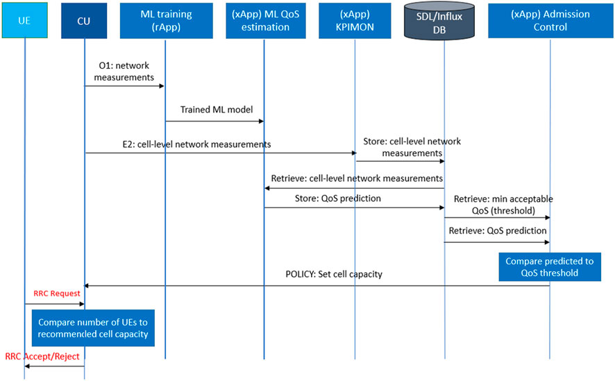
The proposed AC algorithm can be implemented within an O-RAN framework, hosted in the near-RT RIC as an xApp. The algorithm is intended to dynamically control the allowed UE capacity on the cell-level, by sending E2 messages to the CU to control the cell capacities. Such recommended capacities are determined based on the ML-driven QoS predictions per cell. The architecture of such implementation is shown in Figure 6, where the communication over the E2 interface enables ML model deployment in the near-RT RIC, and hence, updating the cell capacities periodically. Functions, such as QoS prediction and capacity recommendation, can be deployed in the near-RT RIC since they need not be executed within stringent real-time constraints. Other functions, like radio resource control (RRC) connection request handling, priority UE handling, will be executed in the CU as to ensure a timely response to incoming connection requests. The machine learning model, used for QoS prediction, can be provided to the near-RT RIC by the non-RT RIC through the A1 interface. An rApp will be responsible for retraining the ML model with updated data collected from the network, then sending the new model back to be used for inference. Alternatively, the retraining process can be performed through offline means (independently from the ORAN framework), and then, deployed onto the near-RT RIC from the SMO through the O1 interface. The xApps and CU functions are defined below to perform these functions:
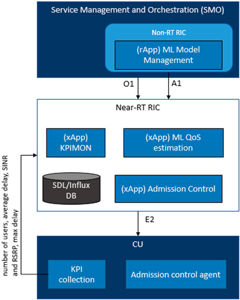
FIGURE 6. ORAN compliant architecture for the AC use-case, comprising of 3x Apps and added functions to the CU.
Given the architecture explained above, the different functions can be split into disaggregated flows, enabling the network to meet the latency requirements for each O-RAN component. There are 4 flows in total, namely data collection, ML-based capacity recommendation, admission decision and performance monitoring and retraining, respectively. The data collection flow is responsible for subscribing to required network measurements on the E2 nodes. Such measurements are received by the KPIMON (KPI monitoring) xApp (O-RAN Alliance, 2019) and saved in the database. Furthermore, the collected data is aggregated at a fixed time-segment and maintained in the near-RT RIC to be used for QoS prediction. The ML-based capacity recommendation flow manages the QoS prediction and dynamic cell capacity control. These functions are performed in the ML QoS estimation and AC xApps, where the final output is a E2 message to the CU. The admission decision flow can be handled in the CU in real-time, where RRC connection requests are handled based on the thresholds recommended by the near-RT RIC. Finally, the performance monitoring and retraining flow is responsible for analyzing the deployed ML model’s performance and triggering retraining in the SMO or the non-RT RIC if necessary. As depicted in Figure 7, the call flow of the proposed algorithm in an ORAN deployment is shown.
To train the ML model, the ML training rApp receives network measurements from the CU, and therefore, passes the trained model to the ML QoS estimation xApp. The KPIMON xApp subscribes to periodic cell-level network measurements, which will be received as indications from the CU over the E2 interface, and hence, stores them in the database. The QoS estimation xApp retrieves the measurements from the database at fixed time segments, runs QoS predictions on the ML model and stores the predictions in the database. The AC xApp retrieves the QoS predictions for post-processing, calculating the recommended capacity per cell. Finally, it packs and sends an E2 message to set the policy on the CU. The CU receives the new policies and uses them for taking admission decisions when it receives an RRC connection request.
3.3 ML model training and simulation setup
For the performance evaluation of the considered AC use case, we train and evaluate a set of ML models to predict the PDU delay in the packet data convergence protocol (PDCP) layer, where the delay is the QoS metric considered by the algorithm. Those models will be utilized for QoS prediction within the system setup, presented in Section 3.2. The adopted ML models include traditional machine learning models such as ridge, k-nearest neighbors (KNN) and random forest regressors, respectively. In addition, we adopt deep learning models including feed-forward neural networks. Therefore, in this section, we discuss the model training process, including the data cleaning operations.
The model training process includes multiple preliminary steps to clean the training data, and preprocessing features including SINR, and reference signal received power (RSRP) to db (decibel) and dbm (decibel milliwatts) scaling, respectively. For cell-level user admission control, we aggregate the data per cell ID, in 1 s time segments, and calculate the mean RSRP, SINR and number of unique UEs on the cell. The original dataset is split into 0.67 and 0.33 over the training and test sets, respectively; and one-third of the training set is used for validation. We train different ML models using UE count, average RSRP and average SINR to predict average PDCP delay on the cell-level. The model hyperparameters are optimized using a grid search algorithm over a set of selected values for each parameter.
Once the model is trained and validated on the test set, it may be deployed to production in a setting similar to that explained in Section 3.2. The preprocessing steps done on the dataset shall be also done on the network measurements collected in runtime before passing them to the model for inference. Furthermore, if the network measurements in the runtime environment are reported in a different unit or scale, the preprocessing shall be changed accordingly. The model would be running predictions in the same time periods as the dataset, of which the output will be used by the AC algorithm for threshold recommendation.
The ML model inference is used to compare the predicted effect an additional UE would have on the average QoS on a given cell. Provided with an operator defined minimum QoS value, the algorithm determines whether admitting another UE would compromise the existing UEs’ QoS.
3.4 NS-3 testbed
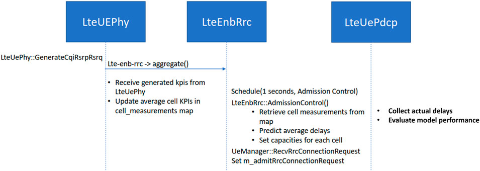
We utilize built-in model files in NS-3 for integration of the proposed AI enabled AC algorithm in the xApp. The model files include LteUEPhy, LteEnbRrc, and LteUePdcp (ns-3, 2019), which represent the main protocol stack layers involved in the AC process, and complies with 3GPP. The NS-3 inference flow for the proposed AC algorithm is demonstrated by Figure 8.
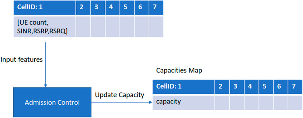
The AC mechanism mainly resides within the RRC layer, and fetches network measurements from the Phy layer using the GenerateCqiRsrpRsrq function of the LteUEPhy model file. The measurements in NS-3 are collected on a transmission time interval (TTI) basis, which is 1 m interval (mimics 5G with numerology 0). However, for model training, cell level measurements are required. This requires pre-processing of the UE generated measurements, which includes aggregating the UE data on a per-cell level with a time granularity of 1 s. The time granularity was chosen to cope with the AC control loop in the RRC layer. The cell level measurements are a map of average RSRP, reference signal received quality (RSRQ), SINR, and number of UEs in each cell within the 1 s interval. The LteEnbRrc also keeps track of the number of UEs admitted per cell, along with the respective achievable capacity per cell. The capacity values per cell are calculated as the maximum number of UEs that could be admitted to the cell without violating the maximum PDCP packet delay, this capacity is updated based on the predicted delay from the ML model. An illustration of the cell level measurements map within LteEnbRrc model file is given in Figure 9.
The trigger policy-based AC flow in the LteEnbRrc layer schedules a call to the AdmissionControl function every 1 s to predict the average delay for each cell, and therefore, update their policies according to the target delay. The ns-3 events scheduler operation calls the AdmissionControl function that runs the predictions, i.e., predicts average delay for all the cells considering one additional UE per cell. The model inference on the cell-level measurements is used to update the capacity for each cell. If the predicted delay for a cell is less than the predefined threshold, the capacity is increased by 1, implying that the cell can admit one more UE.
The third flow is admission decision, which sets the m_admitRrcConnectionRequest flag, based on the capacity threshold of the cell receiving the RRC request. This flow is event driven with the admission/rejection logic embedded within the RecvRrcConnectionRequest function. So, when a cell receives an RRC request from a UE, corresponding CellID variable is retrieved. Using the CellID, the capacity of the cell is retrieved from the stored table. The Boolean variable is set to True if the capacity of the cell is at least one more than the current cell load; otherwise, it is set to False. In the first case, where the m_admitRrcConnectionRequest flag is set to True, the RRC layer sends a confirm message to UE, initiates RRC setup for the UE and changes the UE state to Connected after the successful RRC setup completion. On the contrary, in case of the flag set to False, RRC layer forwards an RRC reject message to the UE along with a wait period, which specifies the interval after which the UE can send a new RRC request.
Some of the flows, which are planned for further enhancements in the NS-3 integration, include a function callback that collects delay values from the PDCP layer. These true delay values will enable model retraining, that will result in model performance improvement during the simulation lifetime.
3.5 Performance evaluation
In this section, we present the performed ML model experiments and respective model performance, based on the ML models and the training process explained in Section 3.3. The adopted ML models include traditional machine learning models such as ridge, k-nearest neighbors (KNN) and random forest regressors, respectively. In addition, we adopt deep learning models including feed-forward neural networks. We discuss the performance metrics used and the model to utilized by the AC algorithm in the NS-3 integration.
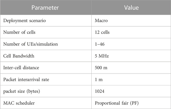
The dataset, for training and validating the adopted ML models, is generated based on NS-3 long-term evolution (LTE) simulations [i.e., lena-dual-stripe scenario (ns-3, 2021)], with a static simulation snapshot. That is, a fixed number of cells and cell bandwidth, in addition to a predefined fixed packet size, and packet arrival rate, respectively. The number of available UEs, for AC, is varied and accordingly, the per-cell load becomes dynamically variant in time such that the obtained dataset is diverse of low and high PDU delay samples. The UE locations are ensured to be diverse and independent by running multiple simulation campaigns with different simulation random seeds. Specifically, 100 simulations have been performed, for 10 different UE counts, each for 10 various random seeds. This results in a wider coverage of the experienced PDU delays, i.e., a wider PDU delay distribution, as depicted by Figure 10. Table 2 lists the main simulation parameters, where we adopt a Macro deployment.
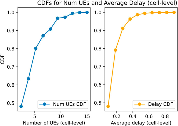
FIGURE 10. Cumulative distribution function (CDF) for Number of UEs per cell and average cell delay in our NS-3 dataset.
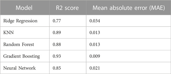
We split the data set into 2,264 training instances and 1116 test instances for training and evaluating the models. Table 3 below provides the models’ performance results on the test set. We use the R2 score and Mean absolute Error (MAE) metrics to evaluate the ML models performances. The R2 score indicates the proportion of the target variable which can be inferred from the input features; and the MAE provides the model’s average error on the observations in the test set, which is to be minimized.
The tests show that the gradient boosting model performs best on the used test set with an MAE of 0.0089. Other models such as KNN, random forest and the neural network model tend to have a similar MAE performance, i.e., from 0.013 to 0.021. Such results are justified by the tree-based models’ capability to learn non-linear patterns in scenarios where data is not available in abundance.
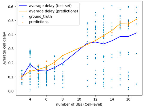
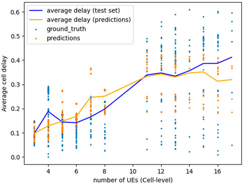
Since the models are intended for use in different environments, the model robustness in different settings is investigated. We compared the performance of the gradient boosting model and the neural network on a high traffic load dataset, generated in identical simulation settings with 50–70 UEs. Those tests are conducted to evaluate the models’ capability of scaling its prediction on traffic patterns not covered in the training set distribution. Figures 11,12 show the ground truth and predicted average delay against the number of UEs/cell, for both models. Figure 11 suggests that using a neural network model would be more robust in environments not previously seen by the model, as its predictions scale up with the increasing number of UEs. In contrast, gradient boosting predictions do not scale up on instances with more than 13 UEs/cell, i.e., the highest number of UEs/cell observed in the training set. Therefore, although gradient boosting yields a lower MAE, using a neural network is suitable when the ML model is intended to operate in an environment different from training.
Next, we evaluate the E2E performance of the proposed admission control algorithm. In particular, the performance comparison metric is the predicted variable from the ML model, i.e., the average PDCP packet delay. Furthermore, we discuss the cost of AC algorithms in terms of the UE RRC rejections to ensure reduced QoS violations. As a performance benchmark, we utilize two schemes: i) no admission control, as an upper bound for the accessibility KPI and ii) fixed threshold admission control, which adopts a maximum number of UEs per cell, and constant across all the cells. The fixed threshold is set by the OAM within the O-RAN framework, and it represents the best practice for operational networks such as LTE. We use 2, 4, and 8 as the threshold values based on the selected cell bandwidth and the stringent target PDCP delay. Moreover, to cater for load variations, we use different number of UEs which are uniformly scattered within the network coverage. Additionally, different values of interpacket arrival rates are used in simulations, which shows the variation in cell load due to higher generated user demand in case of lower interarrival time. The simulation parameters used are same as those given in Figure 12, with the only difference being that the number of UEs are varied between 10 and 100 and considered packet interarrival times are 1 m and 10 m. The stable performance of the DNN based AC algorithm verifies the scalability of the NN based algorithm as the number of UEs are increased beyond the training data ranges.
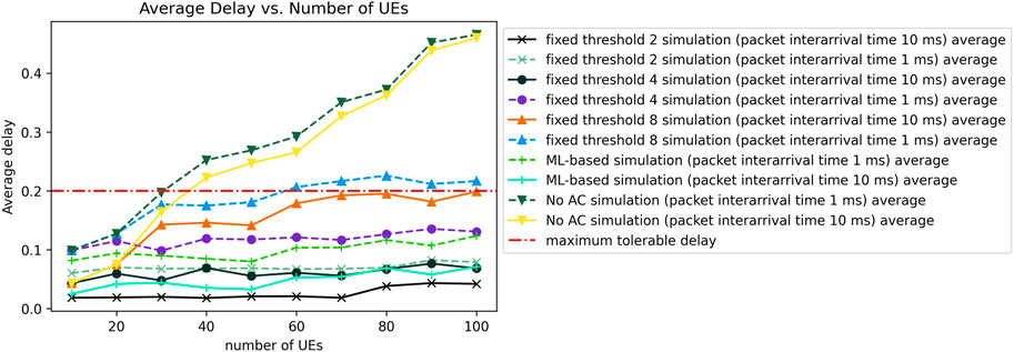
The first presented result in Figure 13 gives a performance comparison in terms of average service delay for the different algorithms and with different number of UEs and variations of the packet interarrival time. From the line graphs, we notice that the fixed threshold admission control with 2 UEs in the scenario of 10 m packet interarrival time shows the lowest delay. This is because of the stringent admission control policy of not allowing more than 2 UEs per cell even when there is sufficient capacity in the cell. As we will see in the later results, this is under utilization of resources, and has an associated cost. While the average delay for ML based AC algorithm remains well below the maximum delay threshold, the average delay for the no AC algorithm (NS-3 default mechanism) increases rapidly above the threshold, particularly as the number of UEs increase beyond 50. Another observation from this figure is that the performance for 10 m packet interarrival time is slightly better than the 1 m scenario, which is as expected since the traffic load is lower for the 10 m interarrival time which results in lower service delay.
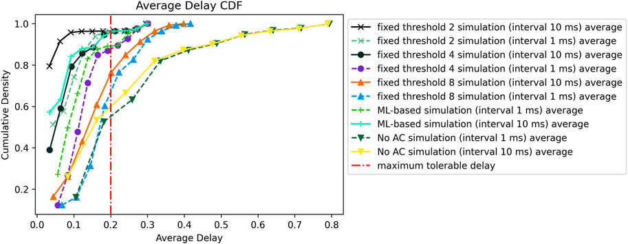
The cumulative distribution function (CDF) representation for the average delay in Figure 14 shows a consistent performance trend with the previous results. The fixed admission control threshold of 2 UEs shows the best results in terms of delay. In terms of the number of cells with a delay value above the threshold of 200 m, the ML based AC algorithm and fixed threshold of 4 UEs show slightly higher percentage of cells as compared to fixed threshold with 2 UEs. For the sake of comparison, in the case of 10 m packet interarrival time, about 95% of the cells satisfy the maximum average delay threshold in case of fixed threshold AC with 2 and 4 UEs, and ML based AC. The value drops to about 75% and 60% in case of fixed threshold with 8 UEs and no AC, respectively. The performance for fixed threshold with 8 UEs is between the no AC and ML based algorithm due to its lenient threshold that accepts a larger number of UEs which consequently results in degrading the average QoS.
The graph in Figure 15 shows the scatter plot of the average service delay for the ML based AC algorithm at different UE population and packet interarrival durations, respectively. We observe that the number of delay violations increase monotonically with the number of UEs in the network. The majority of QoS violations, i.e., when average cell delay is greater than the predefined threshold, while number of UEs is less than 50, comes with the 1 m packet interarrival cases. However, as the number of UEs approaches 100, we observe comparable QoS violations for 1 m and 10 m packet interarrival cases.
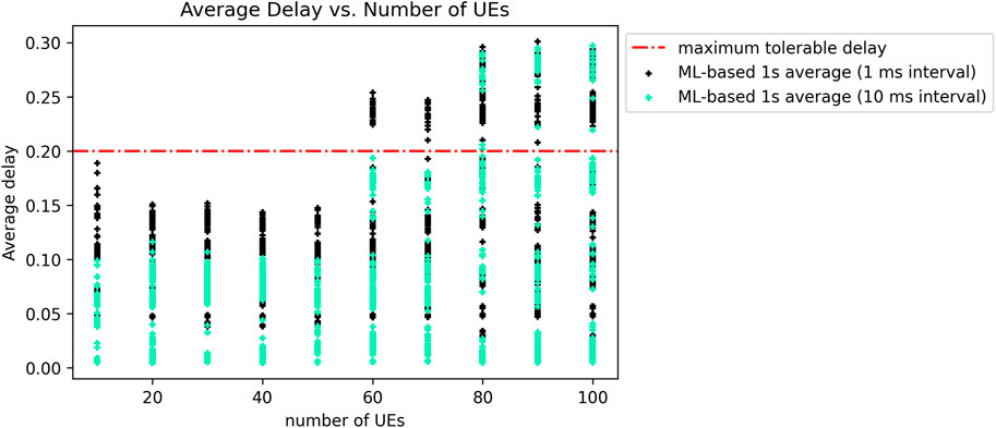
FIGURE 15. Average delay scatter plot vs. no. of UEs for ML based AC at different packet interarrival time.
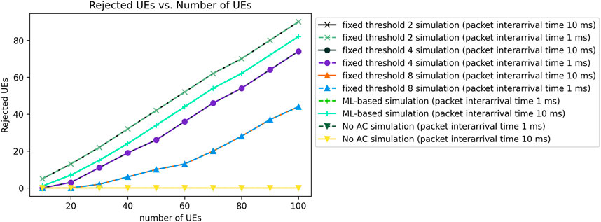
Finally, we present the simulator’s results on rejection rate for the AC algorithms under consideration in Figure 16. While the no AC method has 0 rejection rate since it accepts all RRC requests, due to the stringent thresholds and QoS constraints, the fixed threshold of 2 UEs has a higher UE RRC request rejection rate, which scales linearly as the number of UEs are increased. In general, the rejection rate for all cases increases linearly with the number of UEs in the network, except for fixed UE threshold of 8 UEs and no AC scenario. The high number of RRC rejections is the cost for fixed threshold AC deployment. So, while we increase the UE target QoS to 95% with ML based AC, it also has a lower associated cost for improved UE QoS with a lower number of RRC rejections as compared to fixed AC thresholds of 2 UEs. Therefore, the ML based AC strikes a balance between resource utilization (UE AC in our case), and the average service delay. In comparison with the fixed AC threshold of 4 UEs, although the fixed AC scheme shows slightly lower rejection rate, the ML based AC shows a better delay optimization with 176 delay violations as compared to 195 violations in case of fixed threshold scheme with 4 UEs. For fixed AC with 8 UEs, the lower rejection rate comes at a significant cost of delay violations, depicting that the AC is way too lenient and causes high QoS degradation. Another noticeable fact from the results is that we get identical results for each threshold for the scenarios of 1 m and 10 m packet interarrival times. The high rejection rate can be resolved if traffic steering and RRC request redirecting capabilities are available and activated to dynamically forward rejected RRC requests to neighboring cells with lower loads.
3.6 Future enhancements
The AC PoC use case is an initial effort to implement an xApp algorithm within the NS-3 framework for a real-time decision-making problem. There are multiple limitations in the described implementation, summarized as follows.
• The optimization is performed at a single cell granularity and does not take the entire network under consideration for optimized network-wide performance.
• The algorithm only assumes the packet PDU as the sole performance KPI, and does not take other key factors into account, where examples include the physical resource block (PRB) utilization, power allocation, and target modulation and coding scheme (MCS) per UE.
• The algorithm may lead to service denial of users when the capacity threshold for a cell is met. In this case, the user awaits till the capacity of the cell is enhanced. Optimization of the resulting service denial may be further studied and mitigated by dynamic RRC steering techniques.
Therefore, there are several future enhancements that can be applied to the existing single cell AC algorithm implementation. For instance, a multi-cell user admission control with RRC request steering capabilities can help in balancing the load between cells and ensure that a higher number of UEs are admitted in the network while satisfying their respective target high QoS. Also, if the AC algorithm is applied on handover cases, it will ensure that the QoS of the already connected UEs in the terminating cell is not compromised. From the energy efficiency point of view, we may tune the AC algorithm to transfer RRC requests, in case of rejection from an original cell to cells that will have a minimum increase in power consumption due to the added UE. Finally, for dynamic PRB allocation to different device class types, device class-based thresholds should be introduced to set individual capacity for each class type within the cell.
4 Conclusion
In this work, a comprehensive overview of O-RAN architecture, technology enablers, specifications, open and standardization procedures were rigorously surveyed. First, the key Open RAN architecture design, the main architectural building blocks, and the respective various functional split options and open interfaces have been discussed. Second, the potential of the Open RAN technology to unleash flexible and vendor-neutral interoperability opportunities, are extensively presented. Next, we provided an insight of O-RAN Alliance standardization process along with its working groups focus area, phase I and II use cases and a timeline of selected actions and events related to Open RAN development. Finally, the paper has introduced the unique Open RAN design aspects which enable an efficient and large-scale support of AI/ML within cellular networks, with its novel multi-layer decision making architecture. To illustrate the network performance optimization capability of this new architecture, we designed an ML based AC O-RAN PoC and integrated it within the NS-3 LTE simulator. The ML based approach shows good performance for delay prediction given the number of UEs in the network, and average values of SINR, and RSRQ per cell. Simulation results show that the ML based solution lowers the UE QoS violations at a cost of slightly higher rejection ratio for UE generated RRC requests. We also highlighted future enhancements of this framework which include extending the AC solution to multi-cell environment with traffic steering capabilities that enable real-time load balancing with enhanced QoS to the UEs.
Data availability statement
The original contributions presented in the study are included in the article/supplementary materials, further inquiries can be directed to the corresponding author.
Author contributions
This work was developed with the collaboration of all authors. MA, UH, and MM wrote and revised the manuscript. MM implemented and compiled results under UH and RA’s supervision. GP and MR also reviewed the manuscript. All authors have read and approved the published version of the manuscript.
Conflict of interest
Authors MA, UH, MM, AE, RA, GP, and MR were employed by the company Dell Technologies.
Publisher’s note
All claims expressed in this article are solely those of the authors and do not necessarily represent those of their affiliated organizations, or those of the publisher, the editors and the reviewers. Any product that may be evaluated in this article, or claim that may be made by its manufacturer, is not guaranteed or endorsed by the publisher.
Abbreviations
AC, Admission Control; AI, Artificial Intelligence; BS, Base Station; BU, Baseband Unit; KPI, Key Performance Indicators; MAC, Medium Access Control; MAE, Mean Absolute Error; ML, Machine Learning; MIMO, Multiple-Input Multiple-Output; NF, Network Function; NR, New Radio; Near-RT, Near Real-Time; Non-RT, Non-Real-Time; PDCP, Packet Data Convergence Protocol; OAM, Operation and Maintenance; O-CU, Open Central Unit; O-DU, Open Distributed Unit; O-RU, Open Radio Unit; O-RAN, Open Radio Access Network; QoS, Quality of Service; RRC, Radio Resource Control; RIC, RAN Intelligent Controller; RSRP, Reference Signal Received Power; SINR, Signal to Interference plus Noise Ratio; SMO, Service Management and Orchestration; TIP, Telecom Infra Project; UE, User Equipment.
References
3GPP (2017). Study on new radio access technology: Radio access architecture and interfaces (Release 14). V14.0.0. 3GPP; TR 38.801.
2020 5G America (2020). Transition toward open and interoperable networks. Available at: https://www.5gamericas.org/wp-content/uploads/2020/11/InDesign-Transition-Toward-Open-Interoperable-Networks-2020.pdf (Accessed September 15, 2022).
Bonati, L., Polese, M., D’Oro, S., Basagni, S., and Melodia, T. (2020). Open, programmable, and virtualized 5G networks: State-of-the-art and the road ahead. Comput. Netw. 182, 107516. doi:10.1016/j.comnet.2020.107516
Business Wire (2018). xRAN Forum merges with C-RAN alliance to form ORAN alliance. Available at: https://www.businesswire.com/news/home/20180227005673/en/xRAN-Forum-Merges-C-RAN-Alliance-Form-ORAN (Accessed November 15, 2022).
Caballero, P., Banchs, A., De Veciana, G., Costa-Pérez, X., and Azcorra, A. (2018). Network slicing for guaranteed rate services: Admission control and resource allocation games. IEEE Trans. Wirel. Commun. 17, 6419–6432. doi:10.1109/twc.2018.2859918
Dell Technologies (2022). Accelerating open RAN performance. Available at: https://www.dell.com/en-us/blog/accelerating-open-ran-performance/(Accessed October 14, 2022).
Ding, S., Cao, J., Li, C., Fan, K., and Li, H. (2019). A novel attribute-based access control scheme using blockchain for IoT. IEEE Access 7, 38431–38441. doi:10.1109/access.2019.2905846
Dryjański, M., Kułacz, Ł., and Kliks, A. (2021). Toward modular and flexible open RAN implementations in 6G networks: Traffic steering use case and O-RAN xApps. Sensors 21 (24), 8173. doi:10.3390/s21248173
Kaur, J., Khan, M. A., Iftikhar, M., Imran, M., and Haq, Q. E. U. (2021). Machine learning techniques for 5G and beyond. IEEE Access 9, 23472–23488. doi:10.1109/access.2021.3051557
Liu, Y. F., Dai, Y. H., and Luo, Z. Q. (2012). Joint power and admission control via linear programming deflation. IEEE Trans. Signal Process. 61, 1327–1338. doi:10.1109/tsp.2012.2236319
Manosha, K. S., Joshi, S. K., Codreanu, M., Rajatheva, N., and Latva-aho, M. (2017). Admission control algorithms for QoS-constrained multicell MISO downlink systems. IEEE Trans. Wirel. Commun. 17 (3), 1982–1999.
Matskani, E., Sidiropoulos, N. D., Luo, Z. Q., and Tassiulas, L. (2008). Convex approximation techniques for joint multiuser downlink beamforming and admission control. IEEE Trans. Wirel. Commun. 7 (7), 2682–2693. doi:10.1109/twc.2008.070104
Mehmeti, F., and La Porta, T. F. (2019). “Admission control for consistent users in next generation cellular networks,” in ICC 2019-2019 IEEE International Conference on Communications (ICC), Shanghai, China, 20-24 May 2019 (IEEE), 1–7.
Mehmeti, F., and La Porta, T. F. (2021b). “Admission control for mMTC traffic in 5G networks,” in Proceedings of the 17th ACM Symposium on QoS and Security for Wireless and Mobile Networks, 79–86.
Mehmeti, F., and La Porta, T. F. (2021a). “Admission control for URLLC users in 5G networks,” in Proceedings of the 24th International ACM Conference on Modeling, Analysis and Simulation of Wireless and Mobile Systems, 199–206.
Mitliagkas, I., Sidiropoulos, N. D., and Swami, A. (2011). Joint power and admission control for ad-hoc and cognitive underlay networks: Convex approximation and distributed implementation. IEEE Trans. Wirel. Commun. 10 (12), 4110–4121. doi:10.1109/twc.2011.100811.101381
Monemi, M., Rasti, M., and Hossain, E. (2015). Low-complexity SINR feasibility checking and joint power and admission control in prioritized multitier cellular networks. IEEE Trans. Wirel. Commun. 15 (3), 2421–2434. doi:10.1109/twc.2015.2504084
Moniem Tech (2021). Moniem Tech. Available at: https://moniem-tech.com/2021/08/27/o-ran-alliance-tip-onf-and-open-ran-policy-coalition/(Accessed December 01, 2022).
Nguyen, D. H., Le, L. B., and Le-Ngoc, T. (2015). Multiuser admission control and beamforming optimization algorithms for MISO heterogeneous networks. IEEE Access 3, 759–773. doi:10.1109/access.2015.2441652
ns-3 (2021). lena-dual-stripe. ns-3: src/lte/examples/lena-dual-stripe.cc File Reference (nsnam.org) (Accessed July 15, 2021).
ns-3 LTE modules. Available at: https://www.nsnam.org/docs/release/3.19/doxygen/group__lte.html (Accessed December 09, 2022).
O-RAN Alliance (2018). O-RAN alliance. Available at: https://www.o-ran.org/about (Accessed October 10, 2022).
O-RAN Alliance (2019). O-RAN alliance. Available at: https://docs.o-ran-sc.org/projects/o-ran-sc-ric-app-kpimon/en/latest/(Accessed December 01, 2022).
O-RAN Alliance (2020). O-RAN alliance. Available at: https://static1.squarespace.com/static/5ad774cce74940d7115044b0/t/5e95a0a306c6ab2d1cbca4d3/1586864301196/O-RAN+Use+Cases+and+Deployment+Scenarios+Whitepaper+February+2020.pdf (Accessed October 15, 2022).
O-RAN Working Group 1 (2021). O-RAN architecture description v6.0. O-RAN Alliance. Available at: https://oranalliance.atlassian.net/wiki/spaces/OAH/pages/2331377807/O-RAN+Architecture+Description+v6.0 (Accessed on October, 2022).
O-RAN Working Group 4 (2022). O-RAN fronthaul control, user and synchronization plane specification –v10.0. Technical Report, O-RAN Alliance, 2022. Available at: https://oranalliance.atlassian.net/wiki/spaces/OAH/pages/2587525385/O-RAN+Control+User+and+Synchronization+Plane+Specification+v10.00 (Accessed on November, 2022).
O-RAN Working Group 6 (2020). Cloud architecture and deployment scenarios for O-RAN virtualized RAN v02.02. O-RAN Alliance. Available at: https://oranalliance.atlassian.net/wiki/spaces/OAH/pages/854262284/WG6+O-RAN+Cloud+ Architecture+and+Deployment+Scenarios+for+O-RAN+Virtualized+RAN+v2.1+O-RAN.WG6.CAD-v02.01+-+July+2020 (Accessed on October, 2022).
Parallel Wireless (2020). Everything you need to know about Open RAN. Available at: https://www.parallelwireless.com/wp-content/uploads/Parallel-Wireless-e-Book-Everything-You-Need-to-Know-about-Open-RAN.pdf (Accessed June 15, 2022).
Polese, M., Bonati, L., D'Oro, S., Basagni, S., and Melodia, T. (2022). Understanding O-RAN: Architecture, interfaces, algorithms, security, and research challenges. arXiv preprint arXiv:2202.01032.
Polese, M., Jana, R., Kounev, V., Zhang, K., Deb, S., and Zorzi, M. (2020). Machine learning at the edge: A data-driven architecture with applications to 5G cellular networks. IEEE Trans. Mob. Comput. 20, 3367–3382. doi:10.1109/tmc.2020.2999852
Qiu, J., Tian, Z., Du, C., Zuo, Q., Su, S., and Fang, B. (2020). A survey on access control in the age of internet of things. IEEE Internet Things J. 7, 4682–4696. doi:10.1109/jiot.2020.2969326
Rimedo Labs (2021). O-RAN use cases: Traffic steering. Available at: https://rimedolabs.com/blog/o-ran-use-cases-traffic-steering/(Accessed December 01, 2022).
Rouwet, W. (2022). Open radio access Network (O-RAN) systems architecture and design. Academic Press.
Skehill, R., Barry, M., Kent, W., O'Callaghan, M., Gawley, N., and Mcgrath, S. (2007). The common RRM approach to admission control for converged heterogeneous wireless networks, IEEE Wirel. Commun. 14 (2), 48–56. doi:10.1109/mwc.2007.358964
Tse, D., and Vishwanath, P. (2005). Fundamentals of wireless communication. Cambridge, U.K: Cambridge Univ. Press.
Voss, P. (2017). The third wave of AI. LinkedIn. Available at: https://www.linkedin.com/pulse/third-wave-ai-peter-voss (Accessed October 15, 2022).
Wang, C. X., Di Renzo, M., Stanczak, S., Wang, S., and Larsson, E. G. (2020). Artificial intelligence enabled wireless networking for 5G and beyond: Recent advances and future challenges. IEEE Wirel. Commun. 27 (1), 16–23. doi:10.1109/mwc.001.1900292
Wypiór, D., Klinkowski, M., and Michalski, I. (2022). Open RAN—radio access network evolution, benefits and market trends. Appl. Sci. 12 (1), 408. doi:10.3390/app12010408
Zhou, Y., Ye, Q., Huang, H., and Du, H. (2021). “Deep reinforcement learning based admission control for throughput maximization in mobile edge computing,” in 2021 IEEE 94th Vehicular Technology Conference (VTC2021-Fall), Norman, OK, USA, 27-30 September 2021 (IEEE), 1–6. doi:10.1109/VTC2021-Fall52928.2021.9625281
Keywords: O-RAN, artificial intelligence, machine learning, 5G new radio, RAN intelligent controller (RIC), user admission control
Citation: Alavirad M, Hashmi US, Mansour M, Esswie A, Atawia R, Poitau G and Repeta M (2023) O-RAN architecture, interfaces, and standardization: Study and application to user intelligent admission control. Front. Comms. Net 4:1127039. doi: 10.3389/frcmn.2023.1127039
Received: 19 December 2022; Accepted: 03 February 2023;
Published: 22 March 2023.
Edited by:
Syed Ali Raza Zaidi, University of Leeds, United KingdomReviewed by:
Mona Jaber, Queen Mary University of London, United KingdomFranco Rino Davoli, University of Genoa, Italy
Copyright © 2023 Alavirad, Hashmi, Mansour, Esswie, Atawia, Poitau and Repeta. This is an open-access article distributed under the terms of the Creative Commons Attribution License (CC BY). The use, distribution or reproduction in other forums is permitted, provided the original author(s) and the copyright owner(s) are credited and that the original publication in this journal is cited, in accordance with accepted academic practice. No use, distribution or reproduction is permitted which does not comply with these terms.
*Correspondence: Mohammad Alavirad, bW9oYW1tYWQuYWxhdmlyYWRAZGVsbC5jb20=
 Mohammad Alavirad
 Umair Sajid Hashmi2
 Marwan Mansour