 Letícia Carneiro de Souza*
 Celso Henrique de Souza Lopes
 Rita de Cassia Carlleti dos Santos
 Arismar Cerqueira Sodré Junior
 Luciano Leonel Mendes
- National Institute of Telecommunications, Santa Rita do Sapucaí, Brazil
The millimeter-waves band will enable multi-gigabit data transmission due to the large available bandwidth and it is a promising solution for the spectrum scarcity below 6 GHz in future generations of mobile networks. In particular, the 60 GHz band will play a crucial role in providing high-capacity data links for indoor applications. In this context, this tutorial presents a comprehensive review of indoor propagation models operating in the 60 GHz band, considering the main scenarios of interest. Propagation mechanisms such as reflection, diffraction, scattering, blockage, and material penetration, as well as large-scale path loss, are discussed in order to obtain a channel model for 60 GHz signals in indoor environments. Finally, comparisons were made using data obtained from a measurement campaign available in the literature in order to emphasize the importance of developing accurate channel models for future wireless communication systems operating in millimeter-waves bands.
1 Introduction
The fifth-generation of mobile networks (5G) is considered a revolution in mobile communications since it introduces substantial improvements in terms of capacity, throughput, flexibility, energy efficiency, and end-to-end latency (IMT, 2015). The 5G was initially specified to address the requirements related to different and complementary application scenarios, named: enhanced mobile broadband (eMBB), aiming for high data rates (
As a solution to the spectrum scarcity below 6 GHz, 5G will operate in the millimeter-wave (mm-wave) band (Wang et al., 2018) to enable multi-gigabit data transmission and low latency due to the large available bandwidth. However, high-frequency communications face limitations in terms of propagation mechanisms, which are more challenging than those observed in the sub-6 GHz band used by previous generations of mobile networks (Pi and Khan, 2011; Hemadeh et al., 2017). For instance, heavy rain and hail cause significant attenuation in frequencies above 10 GHz, as raindrops are nearly the same size as the radio wavelengths (Pi and Khan, 2011). Moreover, mm-waves are more susceptible to atmospheric and shadowing effects and do not propagate very well in most solid materials compared to the sub-6 GHz band (Rappaport et al., 2017). Another limiting factor is foliage or vegetation loss, which directly affects the Quality-of-Service (QoS) achieved by systems operating at high frequencies (Singh et al., 2018). On the other hand, this severe attenuation, added to the high path loss, enables spatial reuse of the frequencies, allowing for different links to operate simultaneously in the same frequency without interfering with each other (Yilmaz et al., 2014), which increases the overall capacity of the network. This is specially interesting in indoor environments, where the coverage area may be limited to one room.
The 60 GHz frequency band has drawn attention in the last few years due to the large available bandwidth, which enables high data rate transmission (Geng et al., 2009). Although the oxygen molecules (O2) absorb electromagnetic energy at this frequency, causing intrinsic atmospheric attenuation of roughly 15 dB/km (Yilmaz et al., 2014), this attenuation factor is only a concern for long-distance outdoor communications. For short-distance indoor scenarios, the O2 absorption is negligible (Hemadeh et al., 2017). In this context, the 60 GHz band has been considered for multi-gigabit Wireless Fidelity (Wi-Fi) systems operation, employing the IEEE 802.11ad standard (Sur et al., 2017). Indoor 60 GHz Wireless Local Area Networks (WLANs) can complement the mobile communications systems as an option for data offloading. As the mobile data traffic increases, cellular networks can congestion and mobile data can be transferred to Wi-Fi Access Points (APs) in order to better distribute the traffic load (Wang et al., 2019). This approach is being considered for 5G systems employing the 60 GHz band (Ekti et al., 2016). In addition, the 60 GHz band allows for the reduction of the radios and antennas because of the small wavelength at this frequency (Sharmin and Boby, 2020).
In order to fully exploit the 60 GHz band for indoor communication, it is necessary to model the channel propagation characteristics, including attenuation caused by reflected, diffracted, refracted, scattered waves and material penetration, which can be significantly higher compared to the sub-6 GHz band (Hemadeh et al., 2017). Once properly modelled, this loss can be mitigated by using modern communication techniques, such as beamforming with arrays of high-gain directional antennas (Akdeniz et al., 2014), mMIMO (Heath et al., 2016) and robust coding and modulation schemes (Li et al., 2019).
In the last three decades, several measurement campaigns have been performed aiming to acquire an in-depth knowledge of the spatial and temporal channel characteristics and, consequently, develop new techniques to exploit the mm-wave frequency band. In the 60 GHz band, measurements in indoor and outdoor environments have allowed to define different aspects of the channel, such as time dispersion, penetration losses, propagation mechanisms, path loss, channel shadowing and attenuation (Geng et al., 2005; Rappaport et al., 2012). These campaigns typically consider arbitrary indoor or outdoor locations, with sufficiently space between the transmitter (Tx) and receiver (Rx) locations (one order of magnitude higher than the wavelength λ) for estimating the channel parameters. These measurements are essential for modeling the mm-wave channel at the 60 GHz band and obtaining accurate and reliable prediction and propagation models (Hemadeh et al., 2017).
Although mm-wave propagation models have been widely investigated in literature, the number of tutorials and studies focused on the 60 GHz band in indoor environments is still very limited. For instance, (Sun et al., 2016a) presented and compared the alpha-beta-gamma (ABG) model and close-in (CI) free space reference distance large-scale propagation path loss models aiming at urban microcell (UMi) and urban macrocell (UMa) scenarios. Rappaport et al. reported an overview of the mm-wave propagation channel models for UMi, UMa, and indoor hotspot (InH) scenarios and compared path loss considering four different models in UMi scenario at 28 GHz (Rappaport et al., 2017). In the context of mm-wave propagation characteristics and system design guidelines, (Hemadeh et al., 2017) presented the description of different channel models available for the 28, 38, 60, and 73 GHz frequency bands for different scenarios. In Sun et al. (2018), a review of 3rd Generation Partnership Project (3GPP, 2019) and NYUSIM propagation models have been carried out, focusing on comparing the models for UMi and UMa scenarios. Singh et al. described studies performed in outdoor scenarios aiming to investigate the main propagation mechanisms in the 60 GHz band (Singh et al., 2018). In addition, Sharmin and Boby investigated a methodology for statistical channel modeling for 60 GHz WLAN system in a residential indoor environment and presented a comparative study between the IEEE 802.11ad and Saleh-Valenzuela models (Sharmin and Boby, 2020). Indoor scenarios have also been investigated in (Shabbir et al., 2021), in which the models ABG and CI with a frequency-weighted (CIF) path loss exponent (PLE) are compared for a wide range of frequency bands, including 60 GHz.
This tutorial presents a comprehensive overview of the most relevant indoor propagation models for communications systems operating in the 60 GHz frequency band. Our main contribution is providing in-depth knowledge of channel models available in literature aiming at indoor environments, which have recently become of great interest. In this context, we describe three large-scale path loss models: CI free space with a reference distance, CIF, and ABG. In addition, the channel models that employ these path loss models are reviewed and compared according to five different organizations: 3GPP TR 38.901, 5G Channel Model (5GCM), Millimiter-Wave Based Mobile Radio Access Network for 5G Integrated Communications (mmMAGIC), Mobile and Wireless Communications Enablers for the Twenty-Twenty Information Society (METIS), and Institute of Electrical and Electronics Engineers (IEEE). Aiming to demonstrate the accuracy of the channel models described herein, we present a comparison with a measurement campaign available in the literature for indoor office scenarios. This paper also discusses the propagation in a free space scenario as well as the main propagation mechanisms in indoor environments for the 60 GHz band, such as reflection, diffraction, refraction, scattering, blockage and material penetration properties.
This tutorial is organized as follows. Section 2 presents indoor scenarios propagation characteristics at 60 GHz. Section 3 introduces the large-scale path loss models. Section 4 describes the channel models and related indoor scenarios. Section 5 presents a comparison between the path loss and channel models for indoor scenarios considering real measurements and Section 6 brings the main conclusions of the paper.
2 Propagation Characteristics in Indoor Environments at 60 GHz
The indoor radio propagation channel is complex, since obstacles with different physical properties may impact the signal propagation in different ways. Surface reflection, scattering, blockage and material penetration losses can introduce severe impairments on the received signal, especially at 60 GHz. Therefore, these propagation phenomena must be carefully analyzed in order to model the 60 GHz channel. This section presents the most relevant propagation mechanisms to 60 GHz indoor communications systems. In addition, the free-space propagation is discussed as the basis to comprehend the channel characteristics and models that will be subsequently presented.
2.1 Free-Space Propagation
Before presenting the propagation mechanisms in indoor environments and applying the propagation and prediction models, it is necessary to consider the free-space path loss (FSPL). Free space is considered to be a completely unobstructed region, meaning that there are no obstacles or surfaces interacting with the electromagnetic wave propagating between the transmit and receive antennas. Figure 1 illustrates two antennas perfectly aligned and separated by a distance r in free space. Assuming that the transmit and receive antenna have gains GT and GR, respectively, compared to an isotropic antenna and that the transmit power is denoted by PT, the receive power is given by (Johnson, 1961):
where r is the separation distance between the transmit and receive antennas in m, λ = c/f is the wavelength with c being the phase speed of the wave and f being the operating frequency in Hz. The FSPL is given by the ratio between the transmit power and receive power and it is usually presented in dB as (Johnson, 1961):
where f is the frequency in GHz and r is the distance between the transmitter and receiver in km.
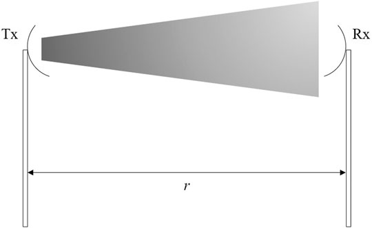
FIGURE 1. Antenna arrangement in a free space radio system.
Equation 1 and Equation 2 show that, for a fixed separation distance and a fixed antenna gain at the transmitter and receiver, the FSPL is proportional to the square of the carrier frequency. This implies in high FSPL at the mm-wave frequency band, when compared to the sub-6 GHz band (Rappaport et al., 2015). Figure 2 presents a comparison between the FSPL obtained at 2.4 and 5 GHz bands, which are mostly used for indoor Wi-Fi networks and the 60 GHz band. Assuming equal transmitter power levels, omnidirectional antennas and no system losses, FSPL at 60 GHz is, respectively, 28 and 22 dB higher than the 2.4 and 5 GHz frequencies. It is important to highlight that the FSPL is a result of the fact that the receive antenna cannot interact with the entire radiation pattern of wavefront (Johnson, 1961). In this context, this loss can be compensated by directional antennas and antenna arrays, which have a substantial gain when compared with omnidirectional antennas. At 60 GHz, the free-space wavelength is 5 mm, which enables arrays with a large number of antennas, as more antennas can fit into a small circuit board or chip. Furthermore, FSPL can be reduced using multiple-input multiple-output (MIMO) and beamforming techniques, as the signals can be directed to a specific point in space (Rappaport et al., 2015).
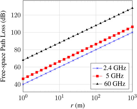
FIGURE 2. Free-space loss comparison between signals operating at 2.4, 5 and 60 GHz.
Although the high FSPL can limit the range of links operating in mm-wave, the severe attenuation at the 60 GHz band can be beneficial in indoor environments, since frequencies can be reused between neighboring rooms. This approach allows for simultaneous transmissions in a given building (Park and Gopalakrishnan, 2009). This means that several hotspots can be placed in an indoor environment without interfering with each other, increasing the network capacity/m2 at 60 GHz. Directional antennas and beam forming can also be advantageous for frequency reuse, as the narrow beams help mitigate interference (Park and Gopalakrishnan, 2009). Figure 3 illustrates a typical dense office environment of 4 cubicles adjacent to each other. The cubicles are separated by a partition wall whose penetration loss must be taken into account. Note that the links can operate at 60 GHz simultaneously without interfering with each other in this scenario. However, there are also a number of scenarios where the interference is non-negligible and the links cannot co-exist unless there is a mechanism to mitigate interference. Therefore, evaluating the propagation and channel characteristics in an indoor environment is critical in determining the overall performance of 60 GHz systems (Park and Gopalakrishnan, 2009).
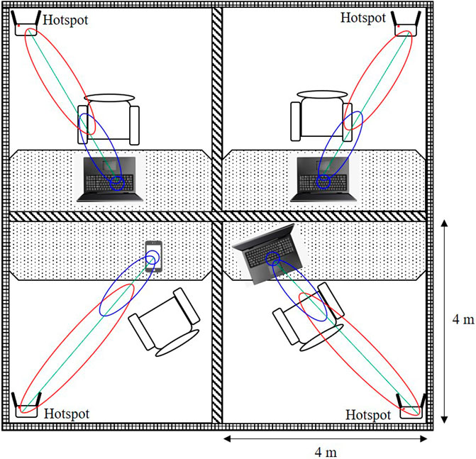
FIGURE 3. Spatial frequency reuse of 60 GHz band in a 4-cubicle indoor office environment.
2.2 Propagation Mechanisms
Indoor propagation models at 60 GHz must consider several characteristics, such as reflection properties of different surfaces, diffraction, blockage, and scattering. These characteristics substantially impact communications on mm-waves (Deng et al., 2016). Due to the short wavelengths, ranging from 1 to 10 mm, the mm-wave signals propagation mechanisms are drastically different from those of sub-6 GHz and, therefore, must be analyzed and studied in order to properly model and evaluate wireless communications systems operating in these frequencies.
Reflected, diffracted and scattered waves from nearby objects result in the multipath fading effect, which influences on the performance of indoor wireless communication systems. Reflection is the dominating factor in the channel delay profile at 60 GHz. Considering a perfectly smooth surface, the reflection would lead to a single wavefront. However according to experimental investigations presented in Maltsev et al. (2010c), each reflected path actually consists of a number of wavefronts propagating in different directions. Because of the fine structures of the reflected surfaces, these wavefronts are closely spaced to each other in time and angular displacements. Hence, the clustering approach is suitable for 60 GHz signal propagation modeling, where each cluster consists of corresponding line-of-sight (LOS) or non-line-of-sight (NLOS) reflected paths (Gustafson et al., 2013). Diffraction occurs when the bending of waves takes place in the same medium. Considering that the dimensions of typical obstacles are large compared to the 60-GHz signal wavelength, diffraction becomes insignificant, as sharp shadow zones are formed (Gustafson et al., 2013). In addition, the 60-GHz propagation channel has a quasi-optical nature, meaning that waves tend to propagate in a straight line. Since the angle of diffraction and size of wavelength are directly proportional, propagation due to diffraction is not viable at the 60 GHz frequency range. Consequently, most of the transmission power is propagated between the transmitter and receiver through LOS and low-order reflected paths (Maltsev et al., 2010b; Sharmin and Boby, 2020).
Transmissions at 60 GHz in indoor environments are highly vulnerable to human blockage due to the small wavelength and the use of narrow beams. Thus, a person crossing the link causes its temporary blockage, which can last as long as the person stands between the transmit and receive antennas. Therefore, it is necessary to characterize and categorize the human blockage at 60 GHz links based on human activity and evaluate its effect on the systems QoS. Moreover, when analyzing the characteristic of the blockage, a 60 GHz device is able to identify its type and determine which action can be taken to minimize the effects of the blockage. In Figure 4, the interaction of propagation mechanisms in internal environments with the human body is illustrated. Characteristics, such as antenna type, link height and the person’s position, have great relevance on the link quality, considering that human-body attenuation of up to 30 dB have already been reported in the literature (Collonge et al., 2004; Semkin et al., 2018). Retransmission and fast session transfer (FST) are some of the mechanisms to deal with the blockage problem for long periods of time. The IEEE 802.11ad standard model considers the above mentioned phenomena in order to predict the attenuation introduced by the wireless channel (Hersyandika, 2016).
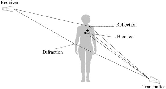
FIGURE 4. Human interaction propagation mechanisms between a transmitter and receiver.
2.3 Material Penetration
The physical characteristics of the materials present in an indoor environment, e.g., building materials, furniture, partitions, and openings (windows, doors, etc.), also play an important role in indoor signal propagation at 60 GHz mainly because these characteristics impact the signal penetration loss (Zhao et al., 2013). In Anderson and Rappaport (2004), penetration loss measurements were conducted at 2.5 and 60 GHz in a typical office environment. The obstacles present between the transmitter and receiver were separated in five categories: drywall, whiteboard, clear glass, mesh glass, and clutter, i.e., office furniture such as chairs, desks, bookcases, and filing cabinets. Table 1 presents a summary of all attenuation factors found in this experiment. Comparing the measured penetration losses, the attenuation introduced by the drywall remained almost constant. On the other hand, the attenuation of whiteboard and mesh glass increases when the frequency varies from 2.5 to 60 GHz. Moreover, the attenuation introduced by clutter decreases when the frequency varies from 2.5 to 60 GHz, since the first Fresnel zone at 60 GHz is considerably smaller, and, therefore, fewer objects are capable of perturbing the signal. The authors in Anderson and Rappaport (2004) also found that the attenuation of the clear glass at 60 GHz is smaller than the attenuation observed at 2.5 GHz. However, the justification for such phenomenon has not been reported in literature and it requires further investigation.

TABLE 1. Comparison between penetration loss measurements obtained at 2.5 and 60 GHz (Anderson and Rappaport, 2004).
Although high levels of material penetration loss degrade link quality and limit the coverage area, it can mitigate interference from neighboring rooms and improve spatial reuse gain. Therefore, 60 GHz signals can be confined to a single room and several hotspots can be placed in an indoor environment, enabling high capacity wireless networks (Park and Gopalakrishnan, 2009).
3 Large-Scale Path Loss Models
The free-space propagation model does not apply in situations where the number of obstacles, diffraction, and reflection points are high. In these environments, the propagation mechanisms and obstructions cause a variation in the received power level even when the transmitter and receiver are stationary. This phenomenon is known as shadowing (Fryziel et al., 2002). Large-scale propagation models aim to predict the signal local mean power level in a given location. This section describes the basic types of large-scale path loss models: the CI free space reference distance path loss model; the CIF model, which is the CI model with a frequency-weighted PLE; and the ABG model.
3.1 CI Model
The CI path loss model uses a CI reference distance based on the FSPL and accounts for the frequency dependency of the path loss. In this model, the path loss in dB is given by (Sun et al., 2016b)
where d ≥ d0 is the 3-D Tx-Rx separation distance in meters, f is the carrier frequency in GHz; d0 is the close-in free space reference distance, chosen large enough to be in the antenna far-field region; n denotes the PLE; and
In indoor environments, d0 is often equal to 1 m (Fryziel et al., 2002). This choice has proven to be accurate and stable over a vast range of microwave and mm-wave frequencies and also creates a standardized modeling approach (Sun et al., 2016b).
3.2 CIF Model
The CIF model is derived from the CI model and is also suitable for multi-frequency modeling. The path loss for the CI model is given in dB by (Eq. 4) when d0 = 1 m (Sun et al., 2016b).
where d ≥ 1 m is the 3D Tx-Rx separation distance in meters, f is the carrier frequency in GHz; n represents the severity of the attenuation with the distance (similar to the PLE in the CI model);
where K is the number of unique frequencies and Nk is the number of path loss data points corresponding to the kth frequency fk. Note that the CIF model simplifies to the CI model when f0 = f or b = 0, i.e. when there is no frequency dependence on path loss.
In the CIF model, the breakpoint distance is defined as the distance where the PLE transitions from free space (n = 2) to the asymptotic two-ray ground bounce model of n = 4 (MacCartney and Rappaport, 2017), which is comprised of a direct ray and a ground reflected ray (Perera et al., 1999). In other words, the breakpoint distance is used as a threshold for an increased path loss coefficient and, therefore, is used as a large scale fading parameter (Zöchmann et al., 2017). Generalizations of the CIF model consider different slopes of path loss before and after a breakpoint distance, known as dual-slope (DS) CIF model. The path loss predicted by the DS CIF model is given by Eq. 6, where dBP is the breakpoint distance in meters. Note that the DS CIF model requires five parameters to predict path loss, whereas the single-slope (SS) model requires only two parameters (Rappaport et al., 2017).
3.3 ABG Model
Assuming distance d in meters and frequency f in GHz, the path loss for the ABG model is given by (Sun et al., 2016b):
where d ≥ 1 m, α and γ are parameters that show the path loss dependence on distance and frequency, respectively, β is an optimized offset value for path loss in dB, and
Similarly to the CIF model, the ABG model is also generalized for DS path loss before and after the breakpoint distance. Equation 8 presents the ABG DS prediction model, where dBP is the breakpoint distance in meters (Sun et al., 2016b). The DS ABG model requires five parameters to predict path loss, whereas the SS require only three. These coefficients are defined aiming to minimize the error between the predicted path loss and the measured data (Rappaport et al., 2017).
4 Channel Models for Indoor Scenarios
Channel models are used to accurately design and compare radio systems, and are critical in evaluating the overall system performance (Rappaport et al., 2017). Recently, many organizations are conducting research aiming to understand the propagation mechanisms at frequencies above 6 GHz and to develop channel models that are able to provide stable, accurate and reliable predictions of the channel impairments. In this section, the most relevant channel models introduced by five organizations are reviewed. These organizations are: 3GPP, 5GCM, mmMAGIC, METIS and IEEE. The indoor channel models are summarized in Tables 2, 3, for LOS and NLOS conditions, respectively.
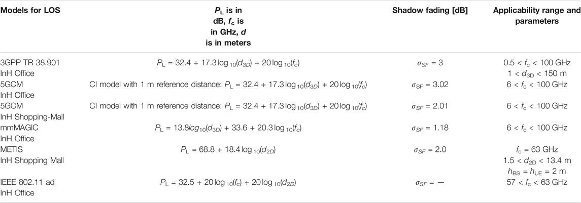
TABLE 2. Channel models for LOS indoor office and shopping mall scenarios (Rappaport et al., 2017).
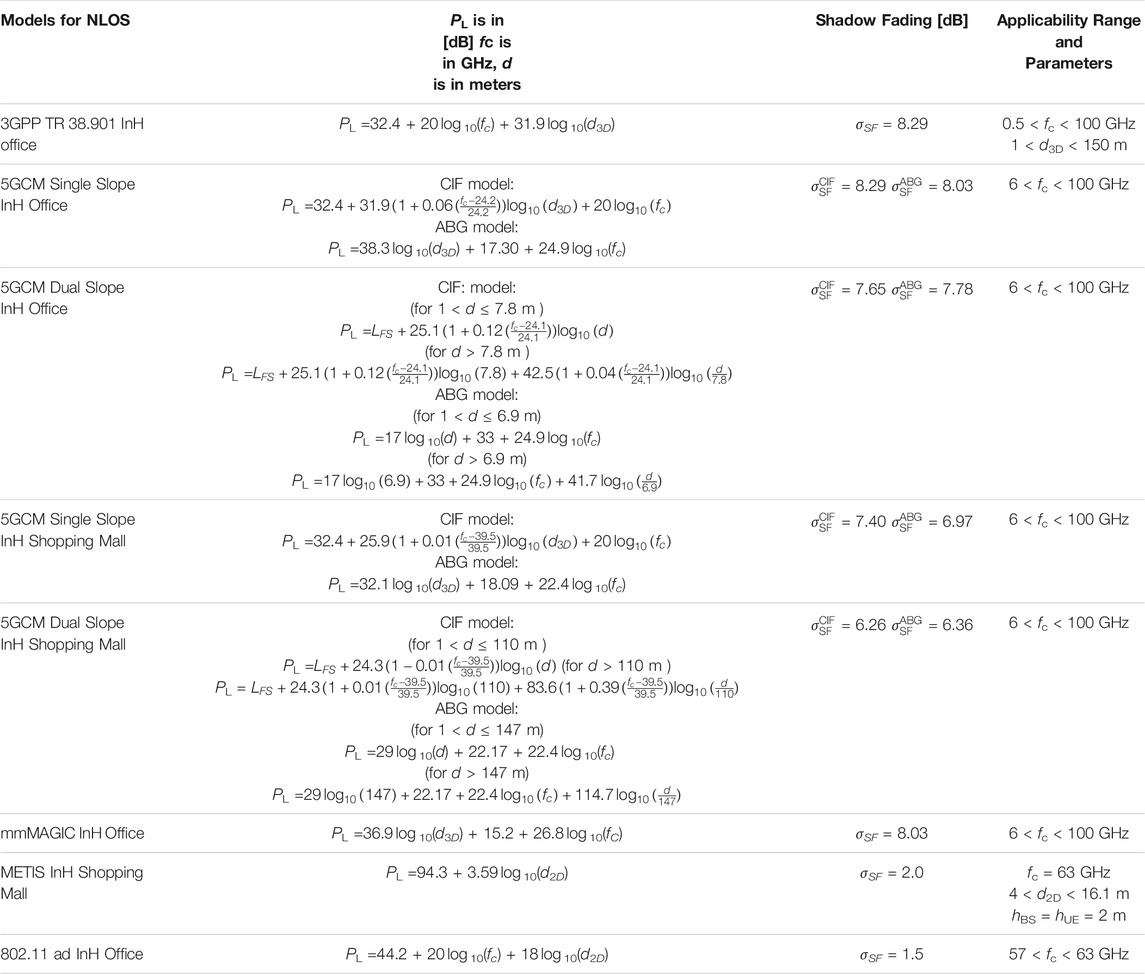
TABLE 3. Channel models for NLOS indoor office and shopping mall scenarios (Rappaport et al., 2017).
4.1 3GPP TR 38.901
The channel models defined in 3GPP TR 38.901 (3GPP, 2019) are generally applicable over the frequency range between 0.5–100 GHz and include several scenarios of interest. The InH office scenarios are valid for distances up to 150 m and are typically comprised of open cubicle areas, walled offices, open areas, and corridors. In addition, the base stations (BSs) are mounted at a height of 2–3 m, either on the ceilings or walls. The path loss models are presented for both LOS and NLOS conditions and employ 3-D Tx-Rx separation distance d3D that accounts for the BS height (hBS) and user equipment (UE) height (hUE), as illustrated in Figure 5.
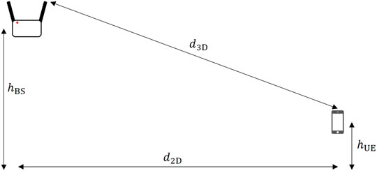
FIGURE 5. Definition of d2D and d3D for indoor scenarios.
The InH-office LOS scenario is similar to the CI model and presents a standard deviation (σSF) of 3 dB. For NLOS, the 3GPP TR 38.901 path loss model uses the ABG model lower-bounded by the LOS path loss with a standard deviation (σSF) of 8.29 dB, resulting in
where PInH-LOS is the path loss in the InH-office LOS scenario and PInH-NLOS is the path loss in the InH-office NLOS scenario. Another option is to use the CI model with 1 m reference distance and σSF of 8.29 dB for the InH-office NLOS scenario. These path loss models and parameters are provided in Tables 2, 3.
4.2 5GCM
The studies presented in the 5GCM white paper (5GCM, 2016) are an extension of the existing 3GPP models and support 5G operation across frequency bands up to 100 GHz. The indoor scenarios described in this paper include open and closed offices, corridors within offices, and shopping malls. The typical office environment is comprised of cubicle areas, walled offices, open areas, and corridors, where the partition walls are composed of different materials. For the office environment, the APs are mounted at a height of 2–3 m either on ceilings or walls. The shopping malls are generally 2–5 stories high and often include an open area. In the shopping mall environment, the APs are mounted at a height of approximately 3 m on the walls or ceilings of the corridors and shops.
The 5GCM channel models presented in Tables 2, 3 were developed based on the large-scale path loss models CI, CIF, and ABG and also accounts for the 3-D Tx-Rx separation distance d3D. The LOS indoor-office and shopping-mall models are similar to the CI model and present σSF of 3.02 and 2.01 dB, respectively. Note that the indoor-office LOS channel model and parameters are identical to the 3GPP TR 38.901 LOS model. For the NLOS condition, the SS CIF and ABG models were employed with σSF of 8.29 and 8.03 dB for indoor-office scenarios, and 7.40 and 6.97 dB for shopping mall scenarios, respectively. In addition, the DS CIF and ABG models were also considered for 5G performance evaluation considering breakpoint distances of 7.8 and 6.9 m for the InH office scenario and 110 and 147 m for the InH shopping mall scenario. According to 5GCM (2016), the DS models may be best suited for InH-shopping mall or large indoor distances (greater than 50 m).
4.3 mmMAGIC
The main objective of the mmMAGIC project (mmMagic, 2017) is to develop advanced channel models for the frequency range of 6–100 GHz. For that purpose, various channel measurements have been conducted for a variety of InH scenarios at multiple frequencies, including 60 GHz. The InH scenarios comprise traditional enclosed offices, semi-closed offices (cubicle areas), and open offices. In this case, the BSs are mounted at a height of 1–5 m and can be placed at the ceilings or on the walls. In addition, channel models were developed for indoor airport scenarios, specifically the gate and the check-in areas, where the BSs should be installed near the ceiling at 4–9 m high.
The mmMAGIC project adopted the ABG path loss model for indoor scenarios, similar to an earlier version of 5GCM (5GCM, 2016), and also accounts for the 3-D Tx-Rx separation distance d3D (see Tables 2, 3). The parameters for the InH channel model were obtained from combining the results of measurement and simulation campaigns at offices and airports environments. The LOS InH channel model presents σSF of 1.18 dB whereas at the NLOS InH scenario the obtained σSF is 8.03 dB.
4.4 METIS
The channel model investigation in the METIS project comprises the analysis of propagation measurements, extensive literature reviews, and simulations. The purpose of this research is to ensure the availability and applicability of relevant propagation models over the frequency range of 6–86 GHz. In this context, the channel model presented in the METIS white paper (METIS, 2015) is similar in form to the ABG model and was adopted for short-range 60 GHz links in shopping mall scenarios, as below
where A and B are the curve-fit parameters, presented in Tables 2, 3.
4.5 IEEE 802.11ad
The IEEE 802.11ad standard (Maltsev et al., 2010a) describes channel models for 60 GHz WLAN systems based on the results of experimental measurements in indoor environments. The InH office scenario is comprised of a cubicle environment, where the wireless AP is located on the ceiling. In both LOS and NLOS scenarios, the path loss model is similar to the CI model. However, no shadowing term is provided in the LOS condition, as the path loss for different antennas configurations match each other very closely and may be approximated by the same polynomial law. For the NLOS condition, the obtained channel model presents σSF equals 1.5 dB. In both conditions, the 2-D distance d2D is employed. These path loss models and parameters are provided in Tables 2, 3.
5 Channel Models Comparison and Analysis for Indoor Scenarios
The channel models introduced in Tables 2, 3 present different characteristics and, therefore, may be suited for different environments. Thus, in order to evaluate the prediction accuracy and sensitivity of the models, it is necessary to compare and analyze the path loss obtained in the scenarios of interest for each model. In this context, this section presents a comparison between the channel models for indoor office and shopping mall environments. Moreover, in order to obtain a more consistent and accurate analysis, the channel models parameters and path loss are also compared to a measurement campaign available in the literature (Anderson and Rappaport, 2004).
5.1 Channel Models Comparison
The channel models were compared considering the BS and the UE heights to be 2 and 1.5 m, respectively, for both indoor office and shopping mall scenarios, defined according to the information available in (5GCM, 2016; mmMagic, 2017; METIS, 2015; Maltsev et al., 2010a). For the InH office scenario, the 2-D distance (d2D) ranges from 1 to 100 m and the 3-D (d3D) distance was calculated, based in Figure 5, as
The METIS model, presented in Tables 2, 3, considers 1.5 m ≤ d2D ≤ 13.4 and 4 m ≤ d3D ≤ 16.1 m for the LOS and NLOS conditions, respectively. However, in order to evaluate the model stability and present a reliable comparison, the shopping mall scenario 2-D distance (d2D) was extrapolated to 200 m and the 3-D distance (d3D) was also evaluated by Eq. 11.
Another key observation is that, in this work, the models comparison is based on the worst-case scenario. In other words, the model considered best suited for a particular scenario is the one that obtained the highest path loss. Consequently, it is possible to obtain a conservative prediction and an increased safety margin for a future project link budget. Figures 6, 7 depict the mean path loss versus Tx-Rx distance obtained with the FSPL, 3GPP, 5GCM, and mmMAGIC channel models, and the IEEE 802.11ad standard in the LOS and NLOS InH office scenario, respectively.
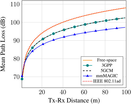
FIGURE 6. Path loss versus Tx-Rx distance comparison among five different channel models in LOS InH office scenario.
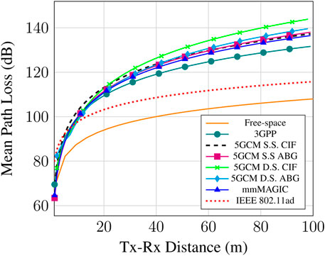
FIGURE 7. Path loss versus Tx-Rx distance comparison among eight different channel models in NLOS InH office scenario.
As shown in Figure 6, the mean path loss obtained with the IEEE 802.11ad standard is identical to the theoretical FSPL, since the PLE is equal to two and no shadowing term is provided for the LOS condition. Moreover, the 3GPP and 5GCM channel models have the same parameters, yielding identical path loss values. On the other hand, the mmMAGIC model presents a more optimistic channel estimation compared to the other models. For instance, considering a Tx-Rx separation distance of 80 m, free-space/IEEE 802.11ad and 3GPP/5GCM mean path losses are approximately 10 and 5 dB higher than the mmMAGIC path loss, respectively, since the mmMAGIC PLE (equivalent to α in the ABG model) is smaller than those presented by the other models. However, at shorter distances, the four models present very similar mean path loss values. For example, at a Tx-Rx separation distance of 10 m, the obtained mean path loss values are 85.3, 83.5, and 88 dB for the 3GPP/5GCM and mmMAGIC models, and the IEEE 802.11ad standard, respectively. For the NLOS condition, Figure 7 shows that the IEEE 802.11ad standard presents a very optimistic path loss estimation. The obtained mean path loss is only 8.6 dB higher than the theoretical FSPL at a Tx-Rx distance of 40 m. On the other hand, the other six models predict much higher path loss values, even at short distances, which is consistent to the NLOS environment. The DS 5GCM models present high mean path loss and are similar to the other models, although the breakpoint distances used are not visible in Figure 7, since they are very short, i.e., 7.8 and 6.9 m for the DS CIF model and DS ABG model, respectively. It is not clear from the data available in (5GCM, 2016) that the DS models are consistent for InH office scenarios, since the use of a breakpoint distance has not been reported in mm-wave measurement campaigns (Rappaport et al., 2017). In addition, the breakpoint distance measurements and calculations were not detailed in 5GCM (2016). However, for distances greater than the breakpoint, the CIF PLE parameter increases from 2.51 to 4.25 and the ABG α parameter increases from 1.7 to 4.17, which is consistent to theoretical breakpoint definition (MacCartney and Rappaport, 2017). In this context, the 5GCM SS channel models are well suited for InH office scenarios for both LOS and NLOS conditions, although the IEEE 802.11ad standard predicts higher mean path loss values for distances greater than 20 m in the LOS condition.
The channel models comparison for the LOS and NLOS InH shopping mall scenarios is presented in Figures 8, 9, respectively. It can be obeserved from Figure 8 that the METIS and the free-space model predict very similar path loss values. Moreover, the 5GCM path loss is approximately 3 dB lower than the path loss obtained with the METIS model at a Tx-Rx separation distance of 100 m. For the NLOS condition, depicted in Figure 9, the path loss predicted by the METIS model is practically constant and less than the FSPL for distances greater than 53 m, due to the very small B parameter. By contrast, the 5GCM DS CIF and ABG channel models predict much higher path losses, specially for distances higher than the respective breakpoint distances (i.e., 110 and 147 m), as shown in Figure 9. In this case, the CIF PLE increases from 2.43 to 8.36 and the ABG α increases from 2.9 to 11.47 for distances greater than the breakpoint. Although the 5GCM white paper predicts that the DS models may be best suited for greater distances (
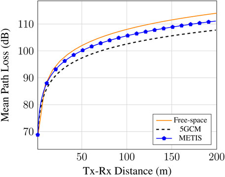
FIGURE 8. Path loss versus Tx-Rx distance comparison among three different channel models in LOS InH shopping mall scenario.
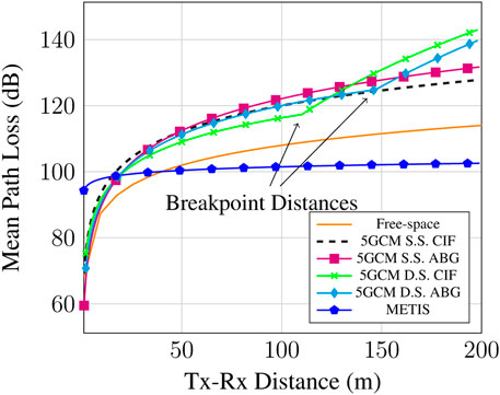
FIGURE 9. Path loss versus Tx-Rx distance comparison among six different channel models in NLOS InH shopping mall scenario.
5.2 Channel Models and Measurement Campaign Comparison
The comparison between the models and the measurement campaign is based on the mean-squared error (MSE), a widely used metric that depends on the average squared difference between the estimated values and the actual value, evaluated as (Yates and Goodman, 2014):
where n is the number of data points, Yi represents the measured values, and
The measurement campaign chosen for the comparison was conducted on the fourth floor of Durhan Hall, Virginia Tech campus, where the structure is made of steel-reinforced concrete, with drywall interior walls, cement blocks, ceramic tiles, carpeted floors and suspended panel ceilings. A total of 8 transmitters and 22 receivers were used in this campaign and the locations were chosen to be representative of a wide range of typical femtocellular propagation scenarios in a working environment, where a low transmission power will serve a single room or part of a floor. The measurements were based on the transmitter and receiver locations in office cubicles and corridors and specifically refer to broadband propagation effects that can be verified in a typical office building, in LOS and NLOS conditions. Pyramidal horn antennas, which had a gain of 25 dBi, were used to compensate path loss in the 60 GHz frequency measurements (Anderson and Rappaport, 2004).
Table 4 presents the mean path loss obtained from the theoretical free-space, 3GPP, 5GCM and mmMAGIC channel models, the IEEE 802.11ad standard, and the measurement campaign results, available in Anderson and Rappaport (2004), for indoor office environments. In addition, Tables 5, 6 present the obtained MSE for each channel model, condition, and environment for comparison. As shown in Table 5, the IEEE 802.11ad standard presents the lowest MSE under the LOS condition in the office cubicle environment. Moreover, it was found that the mmMAGIC model presents the most accurate prediction, i.e., lowest MSE value, under the NLOS condition. By contrast, mmMAGIC channel model presents the least realistic prediction under the LOS condition, i.e. highest MSE value, whereas, for the NLOS condition, the 5GCM SS CIF model was considered the least accurate. Note that, under the NLOS condition, the models present the lowest MSE values, compared to the LOS condition, ranging from 43.88 to 70.02, with the best- and worst-case scenarios being the mmMAGIC and 5GCM SS CIF models, respectively. Considering that the office cubicle environment may have more obstacles and partition walls than the corridor, this results are consistent to the scenario.
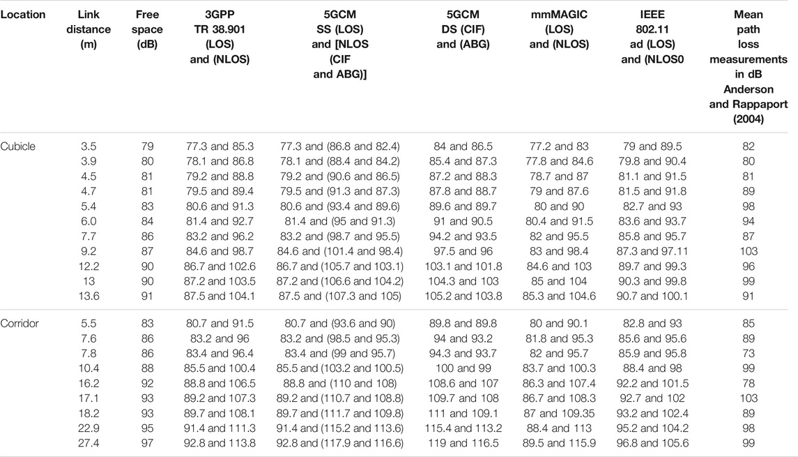
TABLE 4. Summary of measurement results at 60 GHz compared to propagation models for indoor environments.

TABLE 5. MSE values obtained from each channel model for the office cubicle environment.
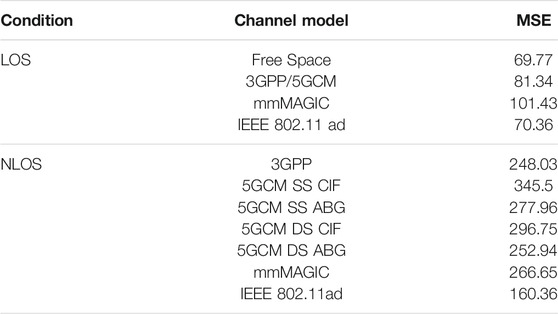
TABLE 6. MSE values obtained from each channel model for the office corridor environment.
The obtained MSE values for the office corridor environment, presented in Table 6, show that the IEEE 802.11ad standard presents the best prediction performance under the LOS condition. On the other hand, the mmMAGIC model presented the lowest MSE under the LOS condition, compared to the other models. Note that, under the NLOS condition, the channel models presented very high MSE values, ranging from 160.36 to 345.5, with the best- and worst-case scenarios being the IEEE 802.11ad standard and 5GCM SS CIF models, respectively. Considering that the office corridor environment may have less obstacles and walls, compared to the cubicle environment, the LOS condition is more likely, which is consistent to the MSE results. Nevertheless, the results presented here may not be accurate for the entire range of indoor scenarios, since it was based on specific measurements and environments.
6 Conclusion
This tutorial provided a comprehensive overview of the 60 GHz mm-wave band propagation characteristics and a comparison of channel models for indoor 5G systems. First, the most relevant propagation mechanisms to 60 GHz indoor communications were presented, including free-space propagation, reflection, scattering, blockage, and material penetration. Then, the large-scale path loss models, i.e., CI, CIF, and ABG, were introduced. In addition, this paper reviewed the most relevant channel models for indoor scenarios introduced by five important organizations and standard bodies: 3GPP, 5GCM, mmMAGIC, METIS and IEEE. Although this paper considers the measurements from one campaign to compare the channel models, this analysis has emphasized the importance of developing accurate channel models for future mm-wave wireless systems. Future works consider the realization of new measurement campaigns in different scenarios at 60 GHz in order to evaluate the channel models.
The results suggest that the 5GCM channel models may be best suited for both LOS and NLOS indoor office and shopping mall scenarios, considering the worst-case scenario. On the other hand, for InH office scenarios, the mmMAGIC and IEEE 802.11ad standard presented a more optimistic channel estimation under the LOS and NLOS conditions, respectively. For InH shopping mall environments, it was found that the METIS model may be unrealistic for the NLOS scenario, since the predicted path loss was practically constant. Furthermore, the comparison made between the predicted path loss and the measurement campaign showed that the mmMAGIC standard is the most accurate prediction model for the office cubicle scenario under the NLOS condition, based on the MSE metric. Moreover, the IEEE 802.11ad model presented the lowest MSE under the LOS condition for both the cubicle and corridor environments. On the other hand, the mmMAGIC and 5GCM SS CIF channel models were the least accurate for both environments under the LOS and NLOS condition, respectively.
Author Contributions
LC, CS, and RC: methodology, conceptualization and investigation. LM: formal analysis. AC and LM contributed to the revision of the manuscript, read and approved the submitted version.
Funding
This work was partially supported by RNP, with resources from MCTIC, Grant No. 01 245.010 604/2 020-14, under the 6G Mobile Communications Systems project of the Radiocommunication Reference Center (Centro de Referência em Radiocomunicações—CRR) of the National Institute of Telecommunications (Instituto Nacional de Telecomunicações—Inatel), Brazil. The authors also thank the financial support from CNPq, CAPES, FINEP, RNP and FAPEMIG.
Conflict of Interest
The authors declare that the research was conducted in the absence of any commercial or financial relationships that could be construed as a potential conflict of interest.
Publisher’s Note
All claims expressed in this article are solely those of the authors and do not necessarily represent those of their affiliated organizations, or those of the publisher, the editors and the reviewers. Any product that may be evaluated in this article, or claim that may be made by its manufacturer, is not guaranteed or endorsed by the publisher.
Supplementary Material
The Supplementary Material for this article can be found online at: https://www.frontiersin.org/articles/10.3389/frcmn.2021.757842/full#supplementary-material
References
3GPP (2019). Study on Channel Model for Frequencies from 0.5 to 100 GHz. Tech. Rep. TR 38, 901. 3rd Generation Partnership Project (3GPP). URL https://portal.3gpp.org/. V16.1.0.
5GCM (2016). “5G Channel Model for Bands up to 100 GHz,” in Tech. rep., 5G Channel Model (5GCM). New York, NY. Available at: http://www.5gworkshops.com/5GCM.html.
Akdeniz, M. R., Liu, Y., Samimi, M. K., Sun, S., Rangan, S., Rappaport, T. S., et al. (2014). Millimeter Wave Channel Modeling and Cellular Capacity Evaluation. IEEE J. Select. Areas Commun. 32 (6), 1164–1179. doi:10.1109/jsac.2014.2328154
Anderson, C. R., and Rappaport, T. S. (2004). In-building Wideband Partition Loss Measurements at 2.5 and 60 GHz. IEEE Trans. Wireless Commun. 3 (3), 922–928. doi:10.1109/twc.2004.826328
Collonge, S., Zaharia, G., and ElZein, G. (2004). Influence of the Human Activity on Wide-Band Characteristics of the 60 GHz Indoor Radio Channel. IEEE Trans. Wireless Commun. 3 (6), 2396–2406. doi:10.1109/twc.2004.837276
Deng, S., MacCartney, G. R., and Rappaport, T. S. (2016). “Indoor and Outdoor 5G Diffraction Measurements and Models at 10, 20, and 26 GHz,” in 2016 IEEE Global Communications Conference (GLOBECOM) (IEEE), 1–7. doi:10.1109/glocom.2016.7841898
Ekti, A. R., Shakir, M. Z., Serpedin, E., Qaraqe, K. A., and Imran, M. A. (2016). On the Traffic Offloading in Wi-Fi Supported Heterogeneous Wireless Networks. J. Sign Process. Syst. 83 (2), 225–240. doi:10.1007/s11265-015-1064-7
Fryziel, M., Loyez, C., Clavier, L., Rolland, N., and Rolland, P. A. (2002). Path-loss Model of the 60-GHz Indoor Radio Channel. Microw. Opt. Technol. Lett. 34 (3), 158–162. doi:10.1002/mop.10402
Geng, S., Kivinen, J., and Vainikainen, P. (2005). “Propagation Characterization of Wideband Indoor Radio Channels at 60 GHz,” in 2005 IEEE International Symposium on Microwave, Antenna, Propagation and EMC Technologies for Wireless Communications (IEEE) Vol. 1, 314–317.
Gustafson, C., Haneda, K., Wyne, S., and Tufvesson, F. (2013). On Mm-Wave Multipath Clustering and Channel Modeling. IEEE Trans. Antennas Propagation 62 (3), 1445–1455.
Heath, R. W., Gonzalez-Prelcic, N., Rangan, S., Roh, W., and Sayeed, A. M. (2016). An Overview of Signal Processing Techniques for Millimeter Wave MIMO Systems. IEEE J. Sel. Top. Signal. Process. 10 (3), 436–453. doi:10.1109/jstsp.2016.2523924
Hemadeh, I. A., Satyanarayana, K., El-Hajjar, M., and Hanzo, L. (2017). Millimeter-wave Communications: Physical Channel Models, Design Considerations, Antenna Constructions, and Link-Budget. IEEE Commun. Surv. Tutorials 20 (2), 870–913.
Hersyandika, R. (2016). Characterization of Human Blockage in 60 GHz Communication. Delft, The Netherlands: Delft University of Technology. Master’s thesis.
IMT (2015). IMT Vision-Framework and Overall Objectives of the Future Development of IMT for 2020 and beyond. Recommendation ITU, 2083:0. Available at: https://www.itu.int/dms_pubrec/itu-r/rec/m/R-REC-M.2083-0-201509-I!!PDF-E.pdf, Technical Report.
Li, Y., Niu, K., and Dong, C. (2019). Polar-Coded GFDM Systems. IEEE Access 7, 149299–149307. doi:10.1109/ACCESS.2019.2947254
MacCartney, G. R., and Rappaport, T. S. (2017). Rural Macrocell Path Loss Models for Millimeter Wave Wireless Communications. IEEE J. Select. Areas Commun. 35 (7), 1663–1677. doi:10.1109/jsac.2017.2699359
Maltsev, A., Erceg, V., Perahia, E., Hansen, C., Maslennikov, R., Lomayev, A., et al. (2010a). Channel Models for 60 GHz WLAN Systems. IEEE document 802, 11. 09/0334r8.
Maltsev, A., Maslennikov, R., Sevastyanov, A., Lomayev, A., and Khoryaev, A. (2010b). “Statistical Channel Model for 60 GHz WLAN Systems in Conference Room Environment,” in Proceedings of the Fourth European Conference on Antennas and Propagation (IEEE), 1–5.
Maltsev, A., Perahia, E., Maslennikov, R., Sevastyanov, A., Lomayev, A., and Khoryaev, A. (2010c). Impact of Polarization Characteristics on 60-GHz Indoor Radio Communication Systems. Antennas Wirel. Propag. Lett. 9, 413–416. doi:10.1109/lawp.2010.2048410
Matthé, M., Gaspar, I. S., Mendes, L. L., Zhang, D., Danneberg, M., Michailow, N., et al. (2017). “Generalized Frequency Division Multiplexing: A Flexible Multi-Carrier Waveform for 5G,” in 5G Mobile Communications (Springer), 223–259.
METIS (2015). “Metis Channel Models,” in Tech. Rep. ICT-317669-METIS/D1.4, Mobile and Wireless Communications Enablers for the Twenty-Twenty Information Society (METIS). URL https://metis2020.com/wp-content/uploads/deliverables/METIS_D1.4_v1.0.pdf. V1.0.
Minyoung Park, M., and Gopalakrishnan, P. (2009). Analysis on Spatial Reuse and Interference in 60-GHz Wireless Networks. IEEE J. Select. Areas Commun. 27 (8), 1443–1452. doi:10.1109/jsac.2009.091014
mmMagic (2017). “Measurement Results and Final Mmmagic Channel Models,” in Tech. Rep. H2020-ICT-671650-mmMAGIC/D2.2, Millimeter-Wave Based Mobile Radio Access Network for Fifth Generation Integrated Communications (mmMAGIC). URL https://5g-mmmagic.eu/results/. V2.0.
Perera, S. C. M., Williamson, A. G., and Rowe, G. B. (1999). Prediction of Breakpoint Distance in Microcellular Environments. Electron. Lett. 35 (14), 1135–1136. doi:10.1049/el:19990834
Pi, Z., and Khan, F. (2011). An Introduction to Millimeter-Wave Mobile Broadband Systems. IEEE Commun. Mag. 49 (6), 101–107. doi:10.1109/mcom.2011.5783993
Rappaport, T. S., Ben-Dor, E., Murdock, J. N., and Qiao, Y. (2012). “38 GHz and 60 GHz Angle-dependent Propagation for Cellular & Peer-To-Peer Wireless Communications,” in 2012 IEEE International Conference on Communications (ICC) (IEEE), 4568–4573.
Rappaport, T. S., Heath, R. W., Daniels, R. C., and Murdock, J. N. (2015). Millimeter Wave Wireless Communications. New Jersey: Pearson Education.
Rappaport, T. S., Xing, Y., MacCartney, G. R., Molisch, A. F., Mellios, E., and Zhang, J. (2017). Overview of Millimeter Wave Communications for Fifth-Generation (5G) Wireless Networks-With a Focus on Propagation Models. IEEE Trans. Antennas Propagat. 65 (12), 6213–6230. doi:10.1109/tap.2017.2734243
Semkin, V., Karttunen, A., Järveläinen, J., Andreev, S., and Koucheryavy, Y. (2018). “Static and Dynamic Millimeter-Wave Channel Measurements at 60 GHz in a Conference Room,” in 12th European Conference on Antennas and Propagation (EuCAP 2018) (London: IET), 1–5. doi:10.1049/cp.2018.0701
Shabbir, N., Kütt, L., Alam, M. M., Roosipuu, P., Jawad, M., Qureshi, M. B., et al. (2021). Vision towards 5g: Comparison of Radio Propagation Models for Licensed and Unlicensed Indoor Femtocell Sensor Networks. Phys. Commun. 47, 101371. doi:10.1016/j.phycom.2021.101371
Shafi, M., Molisch, A. F., Smith, P. J., Haustein, T., Zhu, P., De Silva, P., et al. (2017). 5G: A Tutorial Overview of Standards, Trials, Challenges, Deployment, and Practice. IEEE J. Select. Areas Commun. 35 (6), 1201–1221. doi:10.1109/jsac.2017.2692307
Sharmin, S., Boby, S. M., and Mahmud Boby, S. (2020). Characterization of WLAN System for 60 GHz Residential Indoor Environment Based on Statistical Channel Modeling. Ijwmt 10, 42–58. doi:10.5815/ijwmt.2020.02.05
Singh, H., Prasad, R., and Bonev, B. (2018). The Studies of Millimeter Waves at 60 GHz in Outdoor Environments for IMT Applications: A State of Art. Wireless Pers Commun. 100 (2), 463–474. doi:10.1007/s11277-017-5090-6
Suiyan Geng, S., Kivinen, J., Xiongwen Zhao, X., and Vainikainen, P. (2009). Millimeter-Wave Propagation Channel Characterization for Short-Range Wireless Communications. IEEE Trans. Veh. Technol. 58, 3–13. doi:10.1109/TVT.2008.924990
Sun, S., Rappaport, T. S., Rangan, S., Thomas, T. A., Ghosh, A., Kovacs, I. Z., et al. (2016a). “Propagation Path Loss Models for 5G Urban Micro-and Macro-Cellular Scenarios,” in 2016 IEEE 83rd Vehicular Technology Conference (VTC Spring) (IEEE), 1–6. doi:10.1109/vtcspring.2016.7504435
Sun, S., Rappaport, T. S., Shafi, M., Tang, P., Zhang, J., and Smith, P. J. (2018). Propagation Models and Performance Evaluation for 5g Millimeter-Wave Bands. IEEE Trans. Veh. Technol. 67 (9), 8422–8439. doi:10.1109/tvt.2018.2848208
Sun, S., Rappaport, T. S., Thomas, T. A., Ghosh, A., Nguyen, H. C., Kovacs, I. Z., et al. (2016b). Investigation of Prediction Accuracy, Sensitivity, and Parameter Stability of Large-Scale Propagation Path Loss Models for 5G Wireless Communications. IEEE Trans. Veh. Technol. 65 (5), 2843–2860. doi:10.1109/tvt.2016.2543139
Sur, S., Pefkianakis, I., Zhang, X., and Kim, K.-H. (2017). “Wifi-assisted 60 GHz Wireless Networks,” in Proceedings of the 23rd Annual International Conference on Mobile Computing and Networking, 28–41. doi:10.1145/3117811.3117817
Wang, C.-X., Bian, J., Sun, J., Zhang, W., and Zhang, M. (2018). A Survey of 5G Channel Measurements and Models. IEEE Commun. Surv. Tutorials 20 (4), 3142–3168. doi:10.1109/comst.2018.2862141
Wang, T., Li, P., Wang, X., Wang, Y., Guo, T., and Cao, Y. (2019). A Comprehensive Survey on Mobile Data Offloading in Heterogeneous Network. Wireless Netw. 25 (2), 573–584. doi:10.1007/s11276-017-1576-0
Yates, R. D., and Goodman, D. J. (2014). Probability and Stochastic Processes: A Friendly Introduction for Electrical and Computer Engineers. John Wiley & Sons.
Yilmaz, T., Fadel, E., and Akan, O. B. (2014). “Employing 60 GHz ISM Band for 5G Wireless Communications,” in 2014 IEEE International Black Sea Conference on Communications and Networking (BlackSeaCom) (IEEE), 77–82. doi:10.1109/blackseacom.2014.6849009
Zhao, H., Mayzus, R., Sun, S., Samimi, M., Schulz, J. K., Azar, Y., et al. (2013). “28 GHz Millimeter Wave Cellular Communication Measurements for Reflection and Penetration Loss in and Around Buildings in New York City,” in 2013 IEEE International Conference on Communications (ICC) (IEEE), 5163–5167. doi:10.1109/icc.2013.6655403
Keywords: 5G, 60 GHz, channel models, indoor propagation, propagation models
Citation: Carneiro de Souza L, de Souza Lopes CH, de Cassia Carlleti dos Santos R, Cerqueira Sodré Junior A and Mendes LL (2022) A Study on Propagation Models for 60 GHz Signals in Indoor Environments. Front. Comms. Net 2:757842. doi: 10.3389/frcmn.2021.757842
Received: 12 August 2021; Accepted: 29 November 2021;
Published: 11 January 2022.
Edited by:
Rosdiadee Nordin, Universiti Kebangsaan Malaysia, MalaysiaReviewed by:
Mehran Behjati, National University of Malaysia, MalaysiaOmar B. Abdulghafoor, The American University of Kurdistan, Iraq
Copyright © 2022 Carneiro de Souza, de Souza Lopes, de Cassia Carlleti dos Santos, Cerqueira Sodré Junior and Mendes. This is an open-access article distributed under the terms of the Creative Commons Attribution License (CC BY). The use, distribution or reproduction in other forums is permitted, provided the original author(s) and the copyright owner(s) are credited and that the original publication in this journal is cited, in accordance with accepted academic practice. No use, distribution or reproduction is permitted which does not comply with these terms.
*Correspondence: Letícia Carneiro de Souza, bGV0aWNpYS5jYXJuZWlyb0BtdGVsLmluYXRlbC5icg==