
94% of researchers rate our articles as excellent or good
Learn more about the work of our research integrity team to safeguard the quality of each article we publish.
Find out more
ORIGINAL RESEARCH article
Front. Commun. Netw., 19 October 2021
Sec. Wireless Communications
Volume 2 - 2021 | https://doi.org/10.3389/frcmn.2021.733891
This article is part of the Research Topic5G-and-Beyond Communications for Smart Cities: Networks, Systems and ApplicationsView all 6 articles
 Vladislav Popov1
 Mikhail Odit1
 Jean-Baptiste Gros1
 Vladimir Lenets1Akira Kumagai2Mathias Fink3Kotaro Enomoto2Geoffroy Lerosey1*
As data rates demands are exploding, 5G will soon rely on mmWaves that offer much higher bandwidths. Yet at these frequencies, attenuation and diffraction of waves require point to point communications with beamforming base stations that are complex and power greedy. Furthermore, since any obstacle at these frequencies completely blocks the waves, the networks must be extremely dense, resulting in dramatic increase of its cost. One way to avoid this problem is to redirect beams coming from base stations at many locations with Reconfigurable Intelligent Surfaces, in order to increase their coverage even in cluttered environments. Here we describe and experimentally demonstrate a binary tunable metasurface operating at 28 GHz, based on standard PCB and off the shelves PIN diodes. We show that it can be used as a Reconfigurable Intelligent Surface that beamforms an incoming plane wave at a given angle to one or several outgoing plane waves at angles reconfigurable in real time. Most importantly we use this 20 cm × 20 cm reconfigurable Intelligent Surface alongside software defined radio and up/down converters at 28 GHz, and demonstrate a wireless link between an emitter and a receiver 10 m away, in a non-line-of-sight configuration, hence proving the validity of the approach.
From its inception with Marconi and Hertz one century ago (Hertz, 1893; Marconi, 1909), the field of wireless communications has seen tremendous technological revolutions, which have resulted in impressive new possibilities, and ultimately to their global usage of nowadays and to the growing bandwidth needs we see. For instance, if the concept of beamforming has been known almost from the start (Braun, 1909), it has only become a reality in wireless systems recently, owing to the development of cost effective and compact radiofrequency integrated circuits. Similarly, the impressive usage allowed by forth- and fifth-generations of the telecommunication (4G and 5G), with real time video meetings for instance, would not have been possible without processors incredible breakthroughs of the past decades.
In physics, the past 20 years have been marked by the era of new man-made materials with exotic and non-naturally existing properties: photonic crystals (Joannopoulos et al., 2011), metamaterials (Capolino, 2009) and metasurfaces (Holloway et al., 2012). Meanwhile, impressive approaches were proposed aiming at controlling waves in very complex and scattering media, from acoustics to optics (Fink, 1997; Lerosey et al., 2007; Mosk et al., 2012). Working at the interface between these two fields of research persuaded some of us, a little less than 10 years ago, that the future of wireless communications was in electronically reconfigurable materials and smart electromagnetic environments for superior wave control and optimal data rates.
In a seminal set of papers (Kaina et al., 2014a; Kaina et al., 2014b; Dupré et al., 2015), we proposed to cover part of the walls of an office with real-time electronically tunable metasurfaces that control in a passive way the reflections of the electromagnetic waves emitted by a remote isotropic source. We showed that such approach could improve 10 fold the signal received by a receiver, or on the contrary completely null it, with close to zero electric consumption and very inexpensive hardware. This was the first proposal of the now called Reconfigurable Intelligent Surfaces concept (RIS). RIS is expected to play a key role in improving the coverage area, energy efficiency and data rates of future wireless networks such as 5G and beyond (Dixit et al., 2020). The RIS requires no complex decoding operation and extra power to support electromagnetic wave generation. RIS is represented by a number of passive reflectors providing the adjustment of the reflected/transmitted amplitude and phase, without signal processing and generation (Wu and Zhang, 2020).
The concept went quite unnoticed for some years, while the wireless community’s attention was more on 5G related technologies such as Massive-MIMO (Marzetta et al., 2013; Lu et al., 2014; Björnson et al., 2015). Then the topic started to gain momentum 2 years ago, as it was naturally taken over by the wireless communications community, making now RIS one of the hottest topics in the field. Meanwhile it gave us some time to develop the technology at Greenerwave (Greenerwave, 2018), and to foresee where it could first have practical applications. For standardization and practical reasons, we believe the first real product based on RIS could be a passive access point extender for millimeter-wave (mmWave), and this is what we propose in this paper.
We first build on a recent paper, where we proposed to control radiofrequency waves at 28 GHz using a binary reconfigurable metasurface as a RIS (Gros et al., 2021), and describe a 20 cm × 20 cm FPGA controlled RIS that can act as an access point extender for 5G mmWave. In a third part we show how such RIS can be used to beamform on a given user, and even on several users, simply relying on analytical formulas. In a final part, we demonstrate how our RIS can perform real data link optimization, using software defined radio for the baseband and up/down converters at mmWave in the 5G band (28 GHz). Most importantly, we show that our tunable metasurface can be used to guarantee a data link in a non-line-of-sight (NLOS) situation where mmWaves are conveyed between a corridor and a room, proving the viability of RIS as passive access point extenders for 5G networks.
We note that a detailed performance evaluation of the communication channel improvement lies outside the scope of this paper. However, this question has been already addressed theoretically in a number of papers and an interested reader is referred to, e.g., (Dixit et al., 2020; Wu and Zhang, 2020; Yang et al., 2020; Odeyemi et al., 2021). To the best of our knowledge most of the current papers describing RIS behavior contains results of the theoretical or numerical studies (Basar and Yildirim, 2020; He et al., 2020; Nemati et al., 2020, 2021). The goal of the present study is to experimentally demonstrate the real RIS operating at 28 GHz and show the RIS-empowered communication system operation. The different beamforming algorithms will be considered and several parameters will be discussed to evaluate the performance of the RIS system.
In this work we introduce a reconfigurable intelligent surface (RIS) based on the original design of a reflecting metasurface first described in (Gros et al., 2021). The metasurface is comprised of a set of periodically arranged unit cells with a λ/2 spacing. The design of a single unit cell is shown on Figure 1A. The detailed unit cell description is provided in the above-cited publication by the authors. The unit is designed to control the phase of the reflected field in order to provide a close to the π phase difference between two different states of the electronically controlled element. The control of the reflection field for each polarization is provided by the mutual coupling of the resonances of the main patch resonator and parasitic resonator placed nearby (Kaina et al., 2014a). The switching between resonance-states is performed by the control of the impedance of the PIN diode (MACOM MADP-000907-14020) which is RF-isolated from the biasing voltage through AVX L0201 SMD Inductors (RF chokes). The PIN diodes and chokes are shown correspondingly with blue and green colors in Figure 1A. The biasing voltage is applied to the PIN diodes through the vias. The following dimensions of the elements of the pixels, see Figure 1B, are used in the design: L1 = 1.8 mm, L2 = 1.7 mm, d1 = 0.3 mm, d2 = 0.44 mm, W = 2 mm, p = 5 mm. The PCB is built of two substrates: Meteorwave 8000 (AGC-Nelco, 2020) and FR-4. The Meteorwave 8000 substrate (ɛ = 3.3 and tan(δ) = 0.0016 at 10 GHz) is used as a top dielectric layer to hold resonating elements. The FR-4 substrate (ɛ = 4.3 and tan(δ) = 0.025 at 10 GHz) is used as a bottom layer which is intended to host electronic circuits for the biasing voltage of the PIN diodes.
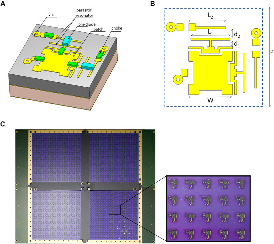
FIGURE 1. The perspective view (A) and layout (B) of the RIS unit cell. (C) Photo of the fabricated 20 cm × 20 cm RIS composed of 4 10 cm × 10 cm reflect arrays, controlled by one FPGA board. The total number of unit cells is 1,600, each with independently control of two polarizations.
The 20 × 20 dual polarization unit cells are placed each λ/2 (at 30 GHz) on a 10 × 10 cm PCB board. Several similar boards can be used in order to increase the total RIS aperture size and consequently the directivity. Here we assemble RIS from four joined together PCBs in order to have a 20 cm × 20 cm aperture (see Figure 1C). The assembly of four smaller metasurfaces instead of using one single big piece has several goals. First is makes the fabrication process cheaper. Second this provides the increase of the directivity of the RIS. The later with other characteristics are summarized in table 1.
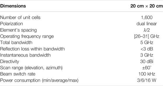
TABLE 1. RIS specifications table.
The RIS is controlled by means of an FPGA control board, which is designed to independently switch each of the 3200 PIN diodes of the RIS. The power consumption of the control board having four connected metasurfaces starts from a few watts when the PIN diodes are in off state and reaches 16 W when all the PIN diodes are switched on. The average power consumption (implying mixed states of the diodes) is typically below 6 W (see Table 1). The switching rate of the RIS state reaches 100 kHz if the pattern of the PIN diodes states is stored in local memory of the board.
In this section we consider algorithms for controlling a RIS. Depending on the relative positions of a transmitting (Tx) antenna, receiving (Rx) antenna and a RIS, one can identify two different modes of RIS operation: near-to-far field and far-to-far field. In the first scenario, one of the antennas (Tx for instance) is placed in the near-field of a RIS, i.e., at a distance when the incident wave cannot be considered as a plane wave. In this mode a RIS and the Tx antenna resemble a common reflect array antenna. The signal emitted by the Tx antenna is reflected by the RIS and focused at an Rx antenna, which is placed in the far-field region. In the second case a RIS operates in the far-to-far field configuration, implying that both Rx and Tx antennas are placed in the far-field of a RIS. This scenario is supposed to be more practical and more common in real-life 5G communication systems, where the RIS can be used as a passive or active access point extender that redirects a signal from a base station towards a user device. In what follows we focus on the developed 20 cm × 20 cm RIS operating in the far-to-far field mode.
When an electromagnetic wave impinges the RIS, the reflected wave will depend on its configuration. In order to increase the signal-to-noise ratio at a receiver, the RIS must form a beam in its direction. A simple analytical model considering the RIS as an array of elements with cos(θ)q radiation pattern (Yang et al., 2016; Gros et al., 2021) can be used to find its configuration for given positions of Tx and Rx antennas. According to this model the electric field of the reflected wave in the direction (θRx, φRx) of the Rx antenna is calculated as follows
where θ and φ are respectively elevation and azimuth angles of the spherical coordinate system having its origin in the center of the RIS, θTx and θRx are the elevation angles towards Tx and Rx antennas, respectively. The reflection coefficient from the nmth pixel is denoted by Γnm and the electric field of the impinging wave at the position of the nmth pixel is Ei (xn, ym). The reflection coefficient can be expressed in terms of the configuration of the RIS as Γnm = ΓONCnm + ΓOFF(1 − Cnm), where Cnm equals one in ON-state and zero in OFF-state of the nmth pixel. The fact that the RIS is built from four metasurfaces separated by 2 cm distance is also taken into account in Eq. 1 through the reflection coefficient Γnm. For indices n and m corresponding to metallized boarders of metasurfaces (of 1 cm width from each side of a metasurface), Γnm equals −1. In this way Eq. 1 allows one to control a large-area RIS built from independent metasurfaces and generate a coherent wavefront.
Based on the Eq. 1, the transmission parameter (S21) between the Tx and the Rx antennas can be simply estimated as
where E0 is the amplitude of the wave sent by the Tx antenna and rRx is the distances from the RIS to the Rx antenna.
In order to maximize the received signal, the absolute value of the right-hand side of Eq. 1 is maximized with respect to the configuration of the RIS. To that end, a simple iterative optimization algorithm can be applied following (Vellekoop and Mosk, 2008). In the first step all pixels are put in OFF-state. Then, the first pixel is turned ON (C11 = 1) and is kept in ON-state, if the goal function increases. Otherwise, the pixel is turned back to OFF-state. The same algorithm is applied to all pixels one-by-one. The number of iterations is limited to the total number of pixels constituting the RIS and equals N2. In comparison to a purely analytical approach of phase gradient typically used for reflectarrays (Pozar et al., 1997; Gros et al., 2021) and transmitarrays (Clemente et al., 2013), the optimization algorithm allows one to achieve sightly better directivity and level of side lobes.
Two examples of applying the presented algorithm are shown in Figure 2, when the incident wave is a plane wave impinging the RIS from (−45° azimuth, 0° elevation). Panels (A) and (B) demonstrate color-maps of the directivity calculated by means of the model, when the RIS is configured to redirect the incident wave towards a receiver at (0° azimuth, −30° elevation) and (20° azimuth, −20° elevation). The RIS configurations corresponding to the far-field radiation patterns appear right below, in panels (D) and (E). The white cross in the middle represents the separation of 2 cm between the four metasurfaces constituting the RIS. In the panels (A) and (B) one can identify two beams: the desired beam (highlighted by a white circle) and the spurious beam (highlighted by a red circle).
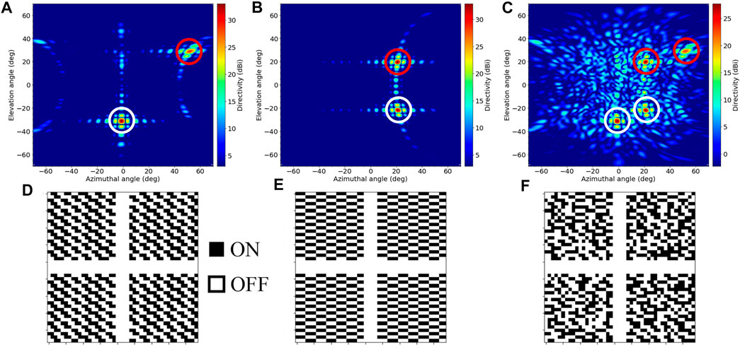
FIGURE 2. (A–C) Numerically calculated far-field radiation patterns created by the RIS illuminated by a plane wave at −45° azimuth incidence and set in a single-beam (A,B) and a double-beam (C) configurations. The desired beams are encircled with the white color and the parasitic ones with the red color. (D–F) Corresponding binary configurations. The white cross represents the separation of 2 cm between the four metasurfaces constituting the RIS.
The appearance of the spurious beam is a consequence of the binary phase control provided by the RIS in the far-to-far field operation mode (both incident and reflected waves have planar wavefront) (Cui et al., 2014; Gros et al., 2021). The spurious beam disappears when one of antennas is in the near-field of the RIS (the incident wave is rather a spherical than a plane wave). Curiously, the spurious beam does not significantly reduce the directivity in comparison to the equivalent configuration of the RIS operating in the near-to-far field mode as it was demonstrated in our earlier work (Gros et al., 2021). Furthermore, the two modes result in similar directivities for the same directions of the desired beam. This fact allows one to approximately estimate the directivity of the RIS in the far-to-far field mode (that can be challenging to measure directly in the experiment) by measuring the radiation pattern of the RIS created in the near-to-far field mode. This is procedure was used in order to estimate the directivity parameter in Table 1 for our RIS operating in the far-to-far field mode.
Along with the directivity of the RIS, measured in the near-to-far field operation mode, other surrogate parameters can be introduced to characterize the performance of the RIS. One of them is the level increase of the transmission between receiving and emitting antennas. This parameter is convenient to use for the optimization procedure and direct measurement. Additionally, a frequency-dependent average received signal-to-noise ratio (SNR) can be used to quantify the system’s performance. In the present paper we mainly focus on transmission incremental between receiving and emitting antennas in case of the NLOS scenario of RIS operation.
It is also worth mentioning that different optimization algorithms can be implemented for the RIS configuration. The straightforward pixel-by-pixel changing algorithm can be replaced by particle swarm method, genetic algorithm and others. The combination of the analytical beamforming and optimization technique can also be used in order to provide fast beam forming and beam scanning mode. In this case the initial beam is formed by estimating the required direction. The phase distribution is calculated analytically. Then the scan procedure applied changing the beam position in the vicinity of the initial position in order to maximize transmission between the receiving and emitting antennas. The elevation and azimuth parameter are changed within a set range in order to perform scanning of the space around the target.
The same RIS can be used serve multiple users at the same time. First of all, the RIS developed in this work allows one to independently control both orthogonal polarizations of an impinging wave. It means that two independent bit-streams can be transferred at the same time when attributed to different polarizations.
On the other hand, a RIS can create multiple beams in independent directions. In this case frequency-division multiplexing can be used for transmitting two independent data streams simultaneously and without the need to switch a RIS between two users. For instance, an optimization procedure based on the one described above can be used to put the RIS in a double-beam configuration, i.e., to redirect a signal from a base-station towards two receivers at different locations. In the first step of this procedure a RIS is put in a single-beam configuration towards the first receiver. The second step is to select a random pixel and put it in the state opposite to the current one. The state of the selected pixel is kept, if the amplitude of the signal at the second receiver increases. Otherwise, the pixel is flipped back. The second step is repeated until the amplitudes of the signal at the first and second receivers are equal. After that, the optimization procedure is completed and final configuration set-ups a RIS to create two beams.
Figure 2C demonstrates a radiation pattern from a RIS in a double-beam configuration, when the impinging wave arrives from the direction (−45° azimuth, 0° elevation) and is redirected towards two independent receivers at (0° azimuth, −30° elevation) and (20° azimuth, −20° elevation). The corresponding RIS configuration is shown in Figure 2F. Similarly to the single-beam scenarios, there are two desired beams and two spurious beams highlighted by white and red circles, respectively.
As one can see, the spurious beam position remains the same as it was for the one beam. It depends only on the position of the corresponding main beam and is not affected by other beams generated by RIS. The energy of the beam obviously decreases due to the redistribution between several beams.
Two beams is not a limit for a RIS and more beams can be controlled simultaneously thus allowing a single base station to serve multiple users at the same time in a NLOS situation. However, multiple-beam control comes at the price of a reduced gain in a given direction, what should be taken into account when calculating the link budget.
At mmWaves a signal from a base station experiences significant fading due to propagation loss and shadowing by buildings, landscape or indoor walls. This problem can be solved by installing additional base stations or access point extenders (passive or active) between existing base stations. In this section we demonstrate experimentally the integration of our RIS in an indoor wireless communication system. This experiment shows a great potential of RIS to provide a robust broadband connectivity even in NLOS situations.
To demonstrate operation of the RIS as a passive access point extender we set up an indoor wireless communication system as illustrated by Figure 3. Here the RIS is placed on a wall of a corridor connecting offices. The Rx and Tx are WR-34 Pyramidal Horn Antennas (Rx) emulating correspondingly an end user terminal (i.e., mobile phone or laptop) and a 5G base station antenna. The distance from the RIS to the Rx antenna is 2 m, the azimuth angle is 52.5° and the elevation angle is −20°. A Tx horn antenna is placed inside an office room providing non-line-of-sight (NLOS) configuration with the Rx antenna. The distance from the RIS to the Rx (Tx) antenna is 2 m (5.5 m), with respect to the normal to the RIS the azimuth angle is 52.5° (−35°) and the elevation angle is −20° (0°). We start by using a Rohde & Schwartz ZVA20 vector network analyzer (VNA) to characterize the channel when the RIS is put in a beamforming configuration or is switched off. In the beamforming configuration the RIS creates a Line-Of-Sight (LOS) between the Tx and Rx antennas. However, in order to efficiently redirect the wave radiated by the Tx antenna towards the Rx antenna, it is necessary to know their precise positions with respect to the RIS. In the given experimental setup we first estimate these locations approximately and then use a feedback from the VNA (S21 parameter) to scan the space in the vicinity of the estimated location antenna positions. In the scanning procedure the RIS is configured according to estimated positions of the Rx and Tx antennas at given iteration. These positions are used as input parameters for the beamforming algorithm described in the previous section. When the S21 parameter is maximized, precise positions of the Tx and Rx antennas are found and the RIS redirects the wave radiated by the Tx antenna towards the Rx antenna establishing the LOS.
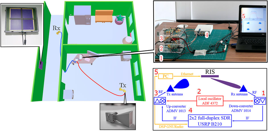
FIGURE 3. Left: A 3D illustration of the experimental setup used to demonstrate RIS-aided indoor wireless communication in a NLOS situation. Right: A photography (top panel) and a schematic (bottom panel) of the communication module represented by a down-converter 1, a local oscillator 2, an up-converter 3, a SDR 4, a PC 5.
Figure 4A compares the path-loss (measured with the VNA) between the Tx and Rx antennas, when the RIS is switched off (the blue curve) and when the RIS is on creating the LOS (the orange curve). It is seen that the RIS allows one to increase the signal power by 30 dB and maintain it at almost constant level in a wide frequency range. The instantaneous bandwidth constitutes more than 3 GHz with respect to 29.5 GHz central frequency. On the other hand, when the RIS is switched off the signal level drops below the noise level at 29.5 GHz and significantly varies with respect to the frequency.
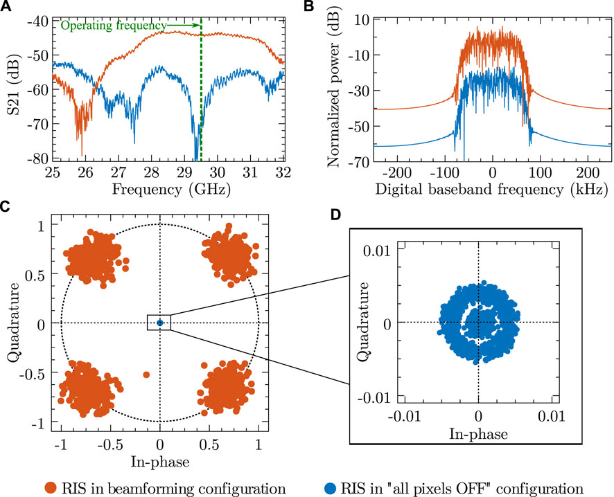
FIGURE 4. (A) S21 parameter measured with a VNA for channel characterization in two configurations of the RIS: all pixels off and beamforming configuration. (B) The signal received by the SDR and put through an RRC filter, when the RIS is off and on. (C) Constellation diagram after timing recovery, equalization and phase and frequency offset compensation, when the RIS is off and on. (D) Close-up of the constellation diagram when the RIS is off.
After the channel is characterized, the VNA is substituted by a wireless communication system shown in Figure 3 on the right panels. Unfortunately, we did not have an access to a real base station and had to built our own setup. In this setup a full duplex software-defined-radio USRP B210 by Ettus Research (SDR) is used in the communication system as a transmitter and a receiver of a modulated signal at an intermediate frequency (IF). The SDR generates a waveform at IF in the Tx channel and provides in-phase and quadrature-phase (IQ) received signal in the digital baseband for further signal processing. The RF front-end of the communication system is represented by an up-converter, a down-converter and a local oscillator (LO) by Analog Devices (ADMV 1013, ADMV 1014 and ADF 4372, respectively). Up- and down-converters multiply the LO frequency by four. A PC controls the RIS via an Ethernet interface and performs digital baseband signal processing of the signal received by the SDR. The signal processing is done with the help of an open software platform GNURadio. A photography of the setup and its schematic are shown on the top right of Figure 3.
To transmit at the RF frequency of 29.5 GHz, the LO is set at 7 GHz and IF generated by the SDR is set to 1.5 GHz. As a data stream was chosen a large array of random numbers, QPSK modulation followed by root-raised-cosine (RRC) filter creates the transmitted waveform. On the receiver chain, the signal received by the SDR is first put through the same RRC filter, after that timing recovery, equalization and compensation for phase and frequency offset is performed. Finally, the received signal is demodulated. It is important to note that even though the Tx and Rx chain of the SDR uses the same clock, one should compensate for the possible frequency offset after the up- and down-conversion processes.
Figure 4B shows normalized power of the received signal at the digital baseband, when the RIS is switched off (the blue curve) and when the RIS is put in the beamforming configuration (the orange curve) to redirect the impinging wave from the Tx antenna towards the Rx antenna. The beamforming by the RIS allows one to enhance the level of the received signal by more than 25 dB and the four symbols of the QPSK modulation are well-distinguished. When the RIS is off, the receiver cannot even lock the constellation as demonstrated by Figures 4C,D.
The results of this section clearly demonstrate how our RIS allows one to restore a data transmission between two antennas in the NLOS situation and establish a solid mmWave communication channel in a complex indoor environment. Furthermore, additional functionality can be added, when a single base station can serve multiple users simultaneously with the help of a RIS. In this case frequency division, code division or time division multiple access techniques can be used Miao et al. (2016).
To conclude, in this paper we have presented a design of a 20 cm × 20 cm binary reconfigurable intelligent surface (RIS) operating at 28 GHz frequency range. The RIS consists of 1,600 independently controlled unit cells. Each of them interact with both horizontal and vertical polarisations of the incident field providing reflection of the wave with variable phase and dissipation less than −3 dB. We show that it is possible to perform analytical beamforming with the RIS imposing proper phase distributions to the RIS elements and recovering the communication channel between two antennas positioned in the non-line-of-sight configuration. When the RIS is switched off the signal does not propagate between antennas. When the RIS is on the signal level is increased 30 dB. Using software defined radio and up/down converters, we finally prove that such RIS can restore a data link in a non line of sight configuration, in a typical office setup. The experiments presented in this paper prove the viability of the concept of passive access point extenders at mmWave, based on tunable metaurfaces used as Reconfigurable Intelligent Surfaces.
The data that support the findings of this study are available from the corresponding author upon reasonable request.
All authors listed have made a substantial, direct, and intellectual contribution to the work and approved it for publication.
Greenerwave acknowledges the support from the European Commission through the H2020 Project through the RISE-6G, HEXA-X under Grant 101015956 and H2020-MSCA-ITN-2020 METAWIRELESS project under Grant 956256.
VP, MO, J-BG, VL, and GL were employed by Greenerwave; AK and KE were employed by AGC Inc.
The remaining author declares that the research was conducted in the absence of any commercial or financial relationships that could be construed as a potential conflict of interest.
All claims expressed in this article are solely those of the authors and do not necessarily represent those of their affiliated organizations, or those of the publisher, the editors and the reviewers. Any product that may be evaluated in this article, or claim that may be made by its manufacturer, is not guaranteed or endorsed by the publisher.
AGC-Nelco (2020). Meteorwave 8000. https://agc-nelco.com/products/meteorwave-8000.
Basar, E., and Yildirim, I. (2020). Indoor and Outdoor Physical Channel Modeling and Efficient Positioning for Reconfigurable Intelligent Surfaces in mmWave Bands. arXiv e-prints , arXiv:2006.02240.
Björnson, E., Sanguinetti, L., Hoydis, J., and Debbah, M. (2015). Optimal design of energy-efficient multi-user mimo systems: Is massive mimo the answer? IEEE Trans. Wireless Commun. 14, 3059–3075. doi:10.1109/TWC.2015.2400437
Capolino, F. (2009). “Theory and Phenomena of Metamaterials,” in Metamaterials Handbook (Florida: CRC Press).
Clemente, A., Dussopt, L., Sauleau, R., Potier, P., and Pouliguen, P. (2013). Wideband 400-element electronically reconfigurable transmitarray in x band. IEEE Trans. Antennas Propagat. 61, 5017–5027. doi:10.1109/tap.2013.2271493
Cui, T. J., Qi, M. Q., Wan, X., Zhao, J., and Cheng, Q. (2014). Coding metamaterials, digital metamaterials and programmable metamaterials. Light Sci. Appl. 3, e218. doi:10.1038/lsa.2014.99
Dixit, D., Joshi, K. C., and Sharma, S. (2020). Performance of Intelligent Reconfigurable surface-based wireless communications using qam signaling. arXiv [Preprint].
Dupré, M., del Hougne, P., Fink, M., Lemoult, F., and Lerosey, G. (2015). Wave-Field Shaping in Cavities: Waves Trapped in a Box with Controllable Boundaries. Phys. Rev. Lett. 115, 017701. doi:10.1103/PhysRevLett.115.017701
Gros, J.-B., Popov, V., Odit, M. A., Lenets, V., and Lerosey, G. (2021). A reconfigurable intelligent surface at mmwave based on a binary phase tunable metasurface. IEEE Open J. Commun. Soc. , 1–1. doi:10.1109/OJCOMS.2021.3076271
He, J., Leinonen, M., Wymeersch, H., and Juntti, M. (2020). “Channel estimation for ris-aided mmwave mimo systems,” in GLOBECOM 2020 - 2020 IEEE Global Communications Conference (New Jersey: IEEE), 1. –6. doi:10.1109/GLOBECOM42002.2020.9348112
Hertz, H. (1893). Electric Waves: Being Researches on the Propagation of Electric Action with Finite Velocity Through SpaceDover histories, biographies, and classics of mathematics and the physical sciences. Dover: Dover Publications.
Holloway, C. L., Kuester, E. F., Gordon, J. A., O'Hara, J., Booth, J., and Smith, D. R. (2012). An Overview of the Theory and Applications of Metasurfaces: The Two-Dimensional Equivalents of Metamaterials. IEEE Antennas Propag. Mag. 54, 10–35. doi:10.1109/MAP.2012.6230714
Joannopoulos, J. D., Johnson, S. G., Winn, J. N., and Meade, R. D. (2011). Photonic Crystals: Molding the Flow of Light. Princeton: Princeton University Press. , rev - revi edn. 10.2307/j.ctvcm4gz9.)
Kaina, N., Dupré, M., Fink, M., and Lerosey, G. (2014a). Hybridized resonances to design tunable binary phase metasurface unit cells. Opt. Express 22, 18881–18888. doi:10.1364/OE.22.018881
Kaina, N., Dupré, M., Lerosey, G., and Fink, M. (2014b). Shaping complex microwave fields in reverberating media with binary tunable metasurfaces. Sci. Rep. 4, 6693. doi:10.1038/srep06693
Lerosey, G., de Rosny, J., Tourin, A., and Fink, M. (2007). Focusing beyond the Diffraction Limit with Far-Field Time Reversal. Science 315, 1120–1122. doi:10.1126/science.1134824
Lu, L., Li, G. Y., Swindlehurst, A. L., Ashikhmin, A., and Zhang, R. (2014). An overview of massive mimo: Benefits and challenges. IEEE J. Sel. Top. Signal. Process. 8, 742–758. doi:10.1109/JSTSP.2014.2317671
Marzetta, T. L., Caire, G., Debbah, M., Chih-Lin, I., and Mohammed, S. K. (2013). Special issue on massive mimo. J. Commun. Netw. 15, 333–337. doi:10.1109/JCN.2013.000064
Miao, G., Zander, J., Sung, K. W., and Slimane, S. B. (2016). Fundamentals of mobile data networks. Cambridge: Cambridge University Press.
Mosk, A. P., Lagendijk, A., Lerosey, G., and Fink, M. (2012). Controlling waves in space and time for imaging and focusing in complex media. Nat. Photon 6, 283–292. doi:10.1038/nphoton.2012.88
Nemati, M., Maham, B., Pokhrel, S., and Choi, J. (2021). Modeling Ris empowered outdoor-to-Indoor communication in mmwave cellular networks. arXiv [Preprint].
Nemati, M., Park, J., and Choi, J. (2020). Ris-assisted coverage enhancement in millimeter-wave cellular networks. IEEE Access 8, 188171–188185. doi:10.1109/ACCESS.2020.3031392
Odeyemi, K. O., Owolawi, P. A., and Olakanmi, O. O. (2021). On the Performance of Reconfigurable Intelligent Surface Aided Power Line Communication System under Different Relay Transmission Protocols. Pier C 111, 119–133. doi:10.2528/PIERC21020803
Pozar, D. M., Targonski, S. D., and Syrigos, H. D. (1997). Design of millimeter wave microstrip reflectarrays. IEEE Trans. Antennas Propagat. 45, 287–296. doi:10.1109/8.560348
Vellekoop, I. M., and Mosk, A. P. (2008). Phase control algorithms for focusing light through turbid media. Opt. Commun. 281, 3071–3080. doi:10.1016/j.optcom.2008.02.022
Wu, Q., and Zhang, R. (2020). Towards smart and reconfigurable environment: Intelligent reflecting surface aided wireless network. IEEE Commun. Mag. 58, 106–112. doi:10.1109/MCOM.001.1900107
Yang, H., Cao, X., Yang, F., Gao, J., Xu, S., Li, M., et al. (2016). A programmable metasurface with dynamic polarization, scattering and focusing control. Sci. Rep. 6, 35692. doi:10.1038/srep35692
Keywords: reconfigurable intelligent surface (RIS), mmWave (millimeter wave), access point extender, beyond 5G, SDR–software defined radio, beamforiming, indoor wireless communication
Citation: Popov V, Odit M, Gros J-B, Lenets V, Kumagai A, Fink M, Enomoto K and Lerosey G (2021) Experimental Demonstration of a mmWave Passive Access Point Extender Based on a Binary Reconfigurable Intelligent Surface. Front. Comms. Net 2:733891. doi: 10.3389/frcmn.2021.733891
Received: 30 June 2021; Accepted: 27 September 2021;
Published: 19 October 2021.
Edited by:
Xuan Liu, Yangzhou University, ChinaReviewed by:
Alexandros-Apostolos A. Boulogeorgos, University of Piraeus, GreeceCopyright © 2021 Popov, Odit, Gros, Lenets, Kumagai, Fink, Enomoto and Lerosey. This is an open-access article distributed under the terms of the Creative Commons Attribution License (CC BY). The use, distribution or reproduction in other forums is permitted, provided the original author(s) and the copyright owner(s) are credited and that the original publication in this journal is cited, in accordance with accepted academic practice. No use, distribution or reproduction is permitted which does not comply with these terms.
*Correspondence: Geoffroy Lerosey, Z2VvZmZyb3kubGVyb3NleUBncmVlbmVyd2F2ZS5jb20=
Disclaimer: All claims expressed in this article are solely those of the authors and do not necessarily represent those of their affiliated organizations, or those of the publisher, the editors and the reviewers. Any product that may be evaluated in this article or claim that may be made by its manufacturer is not guaranteed or endorsed by the publisher.
Research integrity at Frontiers
Learn more about the work of our research integrity team to safeguard the quality of each article we publish.