- 1Intelligent Agricultural Machinery Equipment Engineering Laboratory, Harbin Cambridge University, Harbin, China
- 2College of Mechanical and Electrical Engineering, Northeast Forestry University, Harbin, China
Introduction: To improve the utilization rate of fertilizers, realize the precise spreading of fertilizers in controllable strips, and ensure the uniformity of fertilizer spreading in both longitudinal and transversal directions, a bifurcated swing tube fertilizer spreading device driven by a spatial hammer pendulum crank mechanism was designed.
Methods: First, the drive mechanism was designed based on the cylindrical pair of the mechanism. A mathematical model pendulum equation was used to design the swing tube, and the equation of motion of fertilizer particles was established by analyzing the motion and force of fertilizer particles in fertilizer spreading. The dynamic parameters of the fertilizer spreading device (nozzle height, forward velocity, and swing frequency) were identified as the test factors affecting the uniformity of fertilizer spreading. Second, the coupling model based on MBD-DEM was established, and the coupling simulation analysis of the fertilizer spreading process was carried out using EDEM-RecurDyn software. Taking the nozzle height, forward velocity, and swing frequency as test factors and the uniformity coefficient of longitudinal and transversal fertilizer spreading as evaluation indexes of the fertilizer discharging effect, we analyzed the influence of a single factor on the indexes. Moreover, the ternary quadratic generalized rotating combination response surface test established the regression equations of three factors and two evaluation indexes. Finally, the simulation and bench test were verified under the optimal combination of parameters and compared with the single swing tube bench test with the same parameter conditions.
Results: The results of the single-factor test showed that the fertilizer discharge effect was better when the nozzle height was 350.0–450.0 mm, the forward velocity was 0.5–1.5 m/s, and the swing frequency was 1.40–2.00 Hz. The results of the response surface test proved that the nozzle height, forward velocity, and swing frequency all had a highly significant effect on the uniformity coefficient of fertilizer spreading in the longitudinal and transversal directions (P<0.01). Moreover, the optimization concluded that when the nozzle height is 450.0 mm, the forward velocity is 0.5–0.8 m/s, and when the swing frequency is within the range of 1.40–2.00 Hz, the uniformity coefficient of longitudinal fertilizer spreading is ≤25% and the uniformity coefficient of transversal fertilizer spreading is ≤45%. The results of bench validation showed that the errors of longitudinal and transversal fertilizer spreading uniformity coefficients in the bench test were 3.46% and 1.44%, respectively, and the simulation agreed with the bench test. The results of comparative tests showed that the uniformity coefficient of the longitudinal and transversal of the fertilizer spreading device was reduced by 50.33% and 14.95%, respectively, for the bifurcated swing tube compared with that of the single swing tube. It is proved that the bifurcated swing tube strip fertilizer spreading device can achieve the purpose of uniform fertilizer spreading and performs better than the single swing tube in fertilizer spreading.
Conclusion: The results and methods of this study can provide a reference for the design of swing tube strip fertilizer spreading devices and related fertilizer spreading performance tests.
1 Introduction
Fertilizer application is the fastest and most effective method of increase crop yields (Wang et al., 2023a; Song et al., 2023a). The reasonable application of chemical fertilizers can improve fertilizer utilization and reduce the amount of fertilizer applied, thus improving economic efficiency, reducing environmental pollution, and promoting sustainable agricultural development (Peng et al., 2023; Zhang et al., 2024; Zhan et al., 2023). Therefore, it is of great practical significance to develop the fertilizer spreading device, precisely control the spreading of fertilizers, and improve the utilization rate and yield of fertilizers while saving costs and increasing benefits.
Presently, the mechanical fertilizer spreading method is mainly divided into strip application and spreading. Relevant scholars at home and abroad have conducted a great deal of research on fertilizer spreading devices for different fertilizer spreading methods. For operations mainly targeting large field acreage, several related scholars have conducted research with centrifugal fertilizer spreading as the primary focus. For example, Zinkevičienė et al. (2021) simulated a centrifugal fertilizer spreader using discrete element software to analyze the effect of its structural parameters on fertilizer spreading performance. Hwang and Nam (2021) used the discrete element method to simulate and analyze the motion of fertilizer particles on a spreader. They optimized the position of the louver holes to improve the spreader’s distribution uniformity. Shi et al. (2018) designed a centrifugal variable-speed fertilizer spreader, evaluated the spreader’s fertilizer spreading performance, and optimized the structural parameters through discrete element simulation tests. Centrifugal fertilizer is suitable mainly for spreading in large areas. It has become a commonly used method of fertilizer application on large farms because it has the advantages of a simple structure and sizeable spreading range. For the complex terrain of mountainous hills and other areas, centrifugal spreading of fertilizer does not adapt to the diversified needs of the land, and many related scholars have conducted research in the form of strip spreading. Dun et al. (2023a) designed a swing tube fertilizer spreading device based on controlling a crank-rocker mechanism with no sharp return characteristic. They simulated the swinging fertilizer spreading process of the swing tube through EDEM software to analyze the effects of the swing tube swinging frequency and the change of the swing tube inclination angle on the longitudinal and transversal fertilizer spreading uniformity. Li and Xia (2013) used the principle of bionics to mimic the fertilizer spreading action of the human arm and designed a general-purpose swing tube fertilizer spreader, which consists of a reciprocating tie rod and a swing tube to form a swing mechanism, and analyzed the motion characteristics of the swing tube to determine the parameters of the whole machine to achieve the uniformity of fertilizer spreading. Zhang (2009) also designed a swing tube fertilizer spreader by simulating the action characteristics of fertilizer spreading by the human arm and designed a swing mechanism consisting of an eccentric disk and a swinging fork, in which the swing tube swings back and forth under the drive of the swing mechanism so that the fertilizers work uniformly through the curved outlet. Cao (2016) designed a swing tube spreading mechanism retrofitted to a rotary tiller and determined the optimal parameters of the mechanism using the variation coefficient of the longitudinal and transversal uniformity of lime spreading as an evaluation index. Bai et al. (2023) designed a lightweight dual-mode automatic variable-speed fertilizer application device and control system for strip and spread fertilizer application. Strip fertilization adopts superimposed swing fertilization and is equipped with Hall sensors to control the rotational speed of the fertilizer discharger to improve fertilization uniformity and accuracy, realizing precise variable-rate strip fertilization. Strip fertilizer spreading has good dynamics and adaptability. The more versatile strip spreading is a good choice when targeting more complex operating environments.
Overall, centrifugal spreading has a sizeable operating width, and the uniformity of fertilizer spreading can be achieved by installing different angles of blades on the spreading disc so that the fertilizer thrown out by each blade is different from the distance to achieve the uniformity of fertilizer spreading (Liu et al., 2017). However, the fertilizer falls into the fertilizer spreading disk, and the distribution among the leaves on the disk is uneven; there are also problems with uneven fertilizer application and low fertilizer utilization (Liu et al., 2023). Moreover, centrifugal fertilizer spreading is mainly suitable for large areas of the operating environment. However, it is unsuitable for some of China’s mountains, hills, and other small pieces of land operating environment. The strip spreading can be limited in the horizontal application of fertilizer. In the fertilization operation, it can be better to maintain longitudinal uniformity, fertilizer near the root, and a higher utilization rate (Dun et al., 2023a; Bai et al., 2023).
To further improve the spreading performance of the strip fertilizer spreader, a bifurcated swing tube strip fertilizer spreading device driven by a spatial hammer pendulum mechanism was designed. The bifurcated structural features separate the discharge of fertilizer flow to reduce the fertilizer due to the phenomenon of swinging overlap and thus uniformly spread to the surface, ensuring the longitudinal and transversal bidirectional uniformity of the spreading. According to the effective use of MBD-DEM coupled simulation for the mechanism motion process at home and abroad (Zhao et al., 2023; Chen et al., 2024; Wang et al., 2024). TIn this paper, a joint technical simulation of the fertilizer spreading process is carried out based on analyzing the kinematic properties of fertilizer particles. To investigate the influence of each parameter on the uniformity of spreading, optimize the parameters and carry out bench tests. The accuracy of the coupled simulation experiment results of the bifurcated swing tube strip fertilizer spreading device is verified by bench and comparison experiments, which provides a reference for designing the swing fertilizer spreading device for granular fertilizers. Thus, it can achieve the purpose of evenly spreading fertilizer, improve the efficiency and quality of fertilizer application, and promote the sustainable development of agriculture.
2 Composition and working principle
2.1 Structure composition
During the growth stage of crop cultivation, small amounts of fertilizer are often required for multiple applications. According to the demand for fertilizer in the growth stage of crops, a bifurcated swing tube strip fertilizer spreading device was designed. The unit can be fitted to sizeable agricultural equipment as a fertilizer applicator unit for Great Plains operations or to small stand-alone applicators for mountainous hill operations. As shown in Figure 1 as a fertilizer application monolith, the bifurcated swing tube strip fertilizer spreading device mainly consists of a fertilizer discharger, bifurcated swing tube, hammer pendulum crank, swing tube bracket, and motors, which are assembled in the rear of the tractor with a three-point suspension frame for spreading fertilizers.
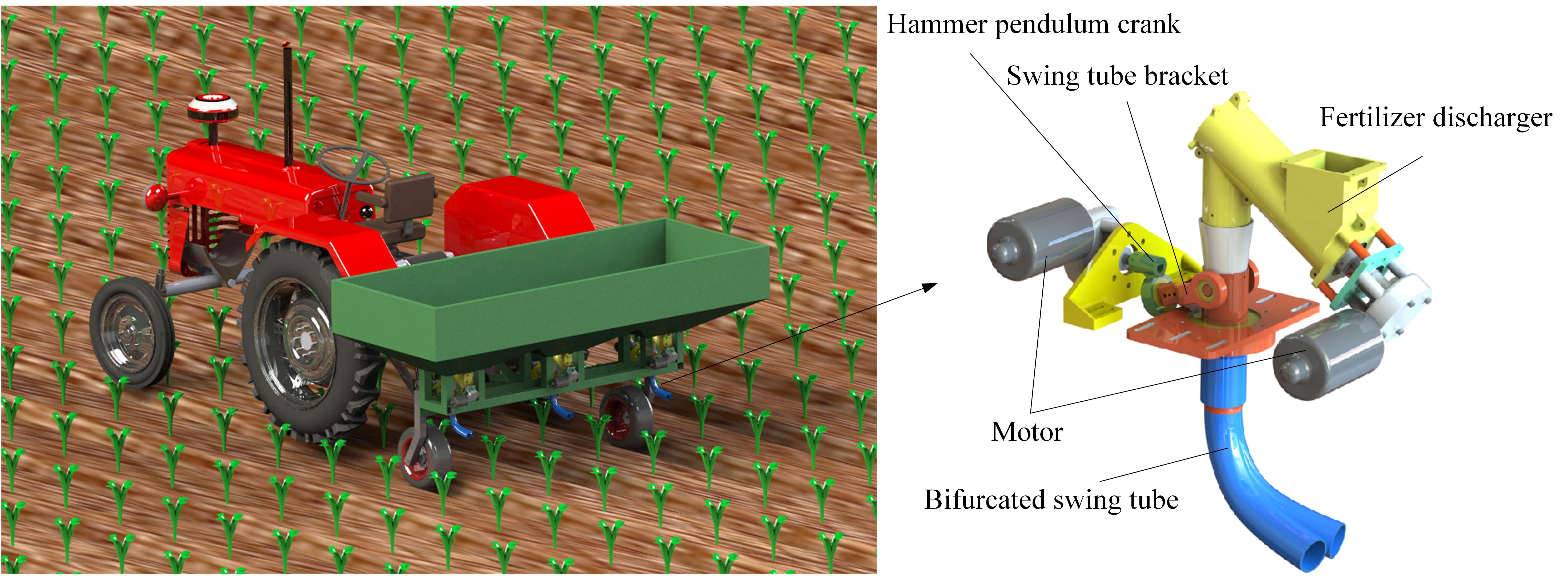
Figure 1. Structure schematic diagram of the bifurcated swing tube strip fertilizer spreading device.
2.2 Working principle
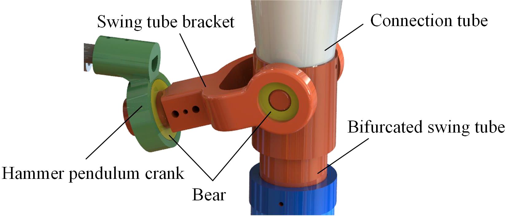
When the bifurcated swing tube strip fertilizer spreading device works, the fertilizer discharged from the fertilizer discharger falls out of the discharge port. Moreover, it enters into the interior of the swing tube. The swing tube bracket is rotationally mated to the bifurcated swing tube using a bearing, and the hammer pendulum crank is fixedly connected to the swing tube bracket. A hammer pendulum crank is fixed to the end of the motor shaft mounted on the frame. During operation, the motor shaft drives the swing tube bracket through the circumferential rotation of the end of the hammer pendulum crank. The swing tube bracket clamps the bifurcated swing tube so that the motor shaft converts the periodic rotation of the hammer crank into a left-right reciprocating swing of the bifurcated swing tube around the swing center. Thus, we realize the function of evenly spreading fertilizer.
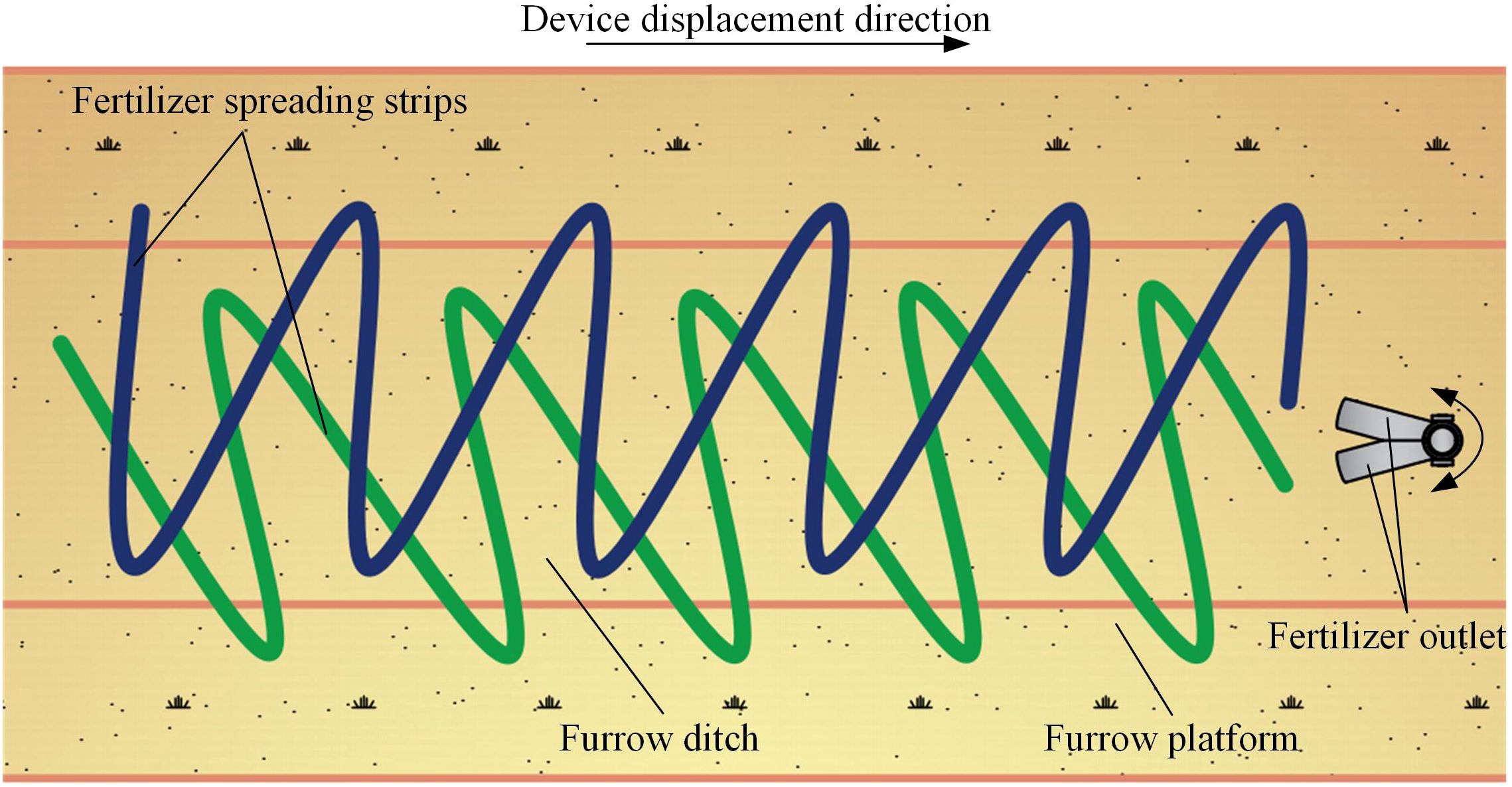
The bifurcated swing tube strip fertilizer spreading device spreads fertilizer in the forward direction of the furrow ditch. Under gravity action, the fertilizer discharger will be discharged from the fertilizer tank into the bifurcated swing tube. Finally, the hammer pendulum mechanism drives the bifurcated swing tube to spread the fertilizer particles. The bifurcated swing tube swings the left and right fertilizer outlets simultaneously as the implement moves forward. It spreads the fertilizer evenly to the ground surface cyclically, forming a single-furrow dual-area fertilizer spreading. Forming overlapping complements at the most concave part of the furrow increases the amount of fertilizer applied in the middle while making the fertilizer fall more sparsely on both sides. The device can throw the fertilizer particles into a double fan shape and effectively ensure the uniformity of the fertilizer in the longitudinal and transversal directions within the furrow to uniformly spread fertilizer on the furrow. A schematic diagram of the fertilizer spreading operation is shown in Figure 2.
3 Mechanism design and motion analysis of the fertilizer particles
3.1 Design of the spatial pendulum mechanism
The bifurcated swing tube uses a spatial hammer pendulum crank mechanism to realize its fertilizer swinging and spreading at the exit of the swing tube. In order to achieve a non-sharp return characteristic for uniformity of fertilizer spreading, the conventional structure of left-right movement of transformation displacement has been changed. Design of space structures using cylindrical pairs. The power input is firstly rotated coaxially in the transverse direction by the cylindrical pair. The power is then transferred to the two cylindrical pairs for power output in up and down, left and right degrees of freedom. The mechanism is shown in Figure 3. The three lower pairs cooperate to complete the synthetic motion of torsion and oscillation so that the trajectory of the output end of the mechanism can achieve the effect of reciprocating oscillation motion. The spatial hammer pendulum crank mechanism in this study uses only the cylindrical pair of the lower pair, which possesses the advantages of simple structure, reliable operation, the ability to withstand larger loads, and transmit more power compared than the higher pair (Fang and Yang, 2022).
The mechanism of this study is constructed by a crank, a connecting rod, and a rocker, where the crank ABC is the input shaft, CD(D0) is the connecting rod, and the rocker EOG is the output shaft. Take the center of the swing tube bracket as the origin, and the y-axis coincides with the drive axis to establish a spatial right-angle coordinate system. At the same time, ABC and EOG are the power input and output that form the rotation axes A and E, respectively. During operation, ABC moves in a fixed axis in space, and owing to the constraint of CD (D0), the cylindrical pair D rotates while twisting the cylindrical pair O. Thus, OG oscillates back and forth in the plane.
To determine whether its motion is reasonable, the degrees of freedom of the spatial mechanism are obtained by subtracting the number of constraints introduced by all the moving parts from the degrees of freedom of the moving parts.
where Fdof is the degree of freedom of the spatial mechanism, n is the number of movable parts, and PI, PII, PIII, PIV, and PV respectively, are the number of kinematical pairs of class I-V.
As the degree of freedom of the overall spatial hammer crank mechanism is one, this mechanism is a single degree of freedom mechanism, and the number of original moving parts is one. The number of original moving parts equals the degree of freedom, and the state of motion is determined.
3.2 Kinematic analysis of the pendulum mechanism
To determine the motion characteristics and performance parameters of the pendulum mechanism, the angle between the OC rod and the y-axis is set to Ψ0, and a vertical line CF to the y-axis at point C. As it rotates in a plane parallel to xoz, CF is used as the radius of gyration so that the angle between CF and the x-axis plane is Ψ1. As the connecting rod CD (D0) oscillates in the xoy plane, let OD0 be at an angle to the y-axis. This results in a system of spatial equations for points C and D0, as shown in Figure 4.
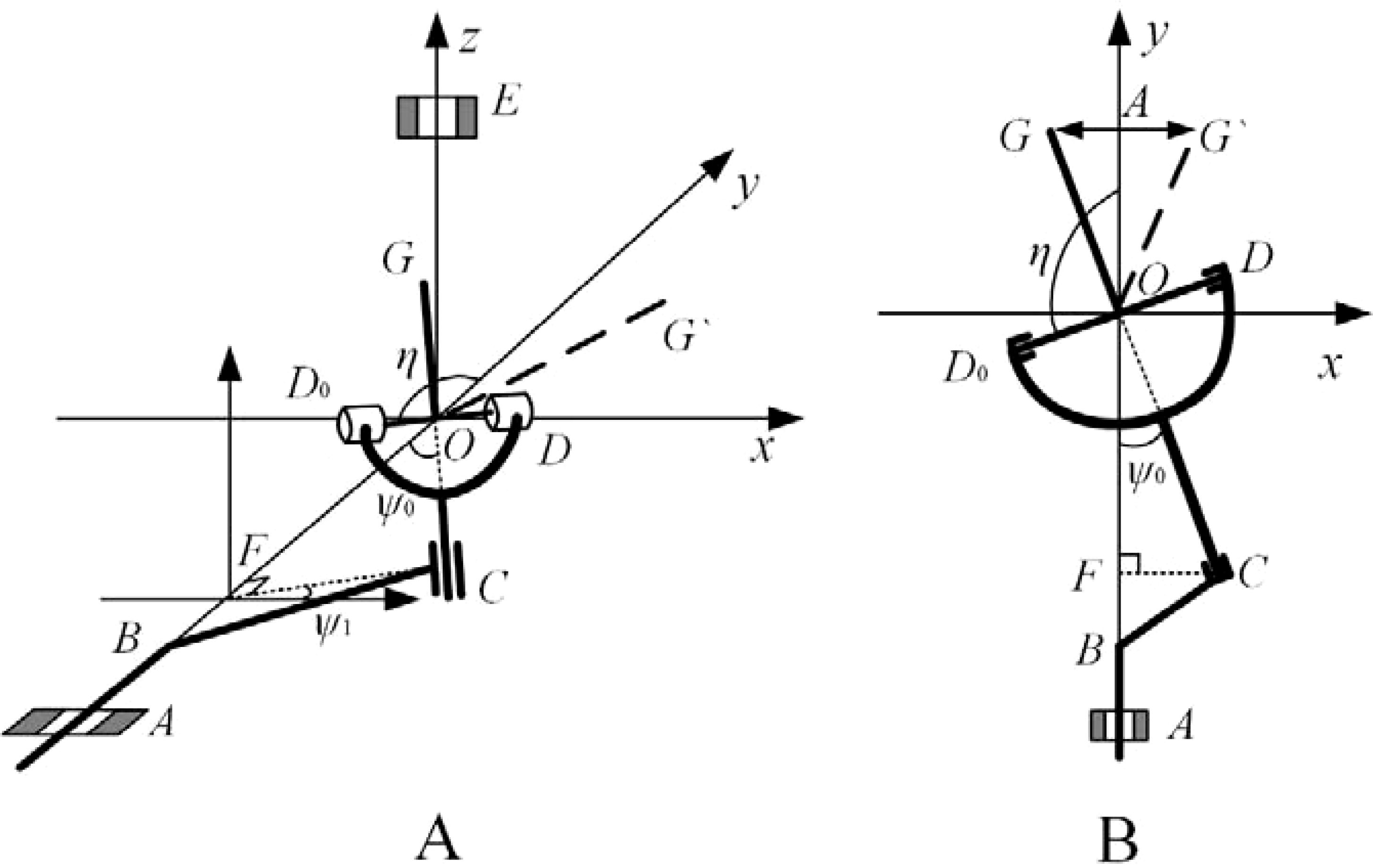
Figure 4. Schematic diagram of the spatial hammer pendulum crank mechanism principle. (A) Spatial view. (B) Top view.
According to the working principle of the spatial pendulum mechanism, the moving range of the two points D and D0 of the connecting rod CD (D0) is always in the xoy plane and oscillates with the rotation of BC. As OC is perpendicular to the OD line, there is:
The above equation is collated to give the following equation:
The first order derivation of Equation 6 is then performed.
The second order derivation of Equation 6 is then performed.
When Ψ1 = -π/2 or π/2, η = π/2, , , Through the above analysis can be seen at this moment for the angle function inflexion point, in the angle η = π/2+Ψ0 and η = π/2-Ψ0 range to achieve the angle of positive and negative conversion, to achieve the spatial pendulum mechanism in the spatial rotation of the movement of the left and right swing motion for the purpose of the power output. Moreover, the design of the horizontal length of the swing tube can be derived from the joint Equations 12 and 13:
Included among these,
where A is the range of swing at the end of the swing tube (mm).
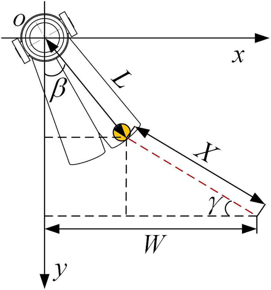
The fertilizer spreading top view schematic is shown in Figure 5. Take the actual field operation of maize, tiny single rows with a width of approximately 60–70 cm between the rows, as an example. As the bifurcated swing tube fertilizer spreading device only needs to spread fertilizer evenly to the two sides of the ridge and furrow when working, to meet the agronomic requirements of maize planting with a minimum spacing of 60 cm between the ridges, the range W of spreading applied at the swing tube mouth shall be satisfied [Equation (11)].
where β is the angle between the unilateral swing tube and the longitudinal direction (°), γ is the angle between the fertilizer spreading path and the lateral direction (°), L is the horizontal length of the swing tube (mm), and X is the distance from the fertilizer throwing plane (mm).
3.3 Swing tube design
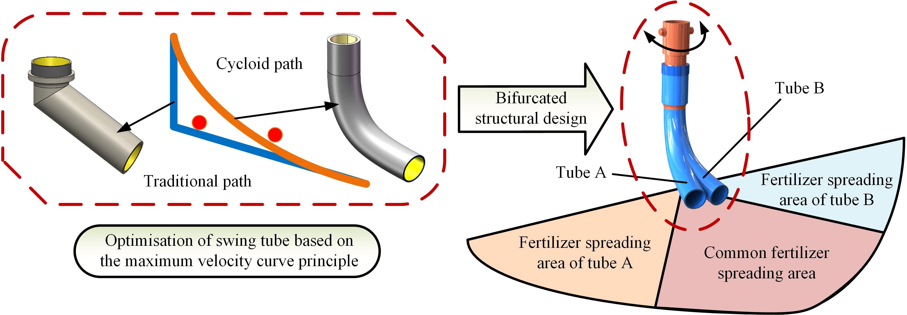
The fertilizer spreading tube’s structure directly affects the fertilizer application’s effect and the uniformity of its distribution on the ground. Conventional swing tubes are mainly angled for downward application and do not have smooth curved surfaces (Dun et al., 2023a; Li and Xia, 2013; Zhang, 2009; Bai et al., 2023). This structure will lead to slow fertilizer discharge or fertilizer congestion under certain circumstances; therefore, the design of the swing tube shape using the maximum velocity curve principle can be better than the straight line path under the exact height of the fertilizer discharge effect in the shortest possible time to discharge the fertilizer in the swing tube (Wu et al., 2023; Yang et al., 2024). In addition to the fertilizer path in the swing tube, the structure of the swing tube also influences the fertilizer spreading effect. The traditional swing tube spreading device is usually a single tube implementation; its structure is simple and easy to implement. However in fertilizer application, it has a giant swing and causes a more concentrated fertilizer drop point. In response to this phenomenon, a bifurcated swing tube structure was designed with two fertilizer-spreading tubes protruding from one side in the same drop tube, as shown in Figure 6.
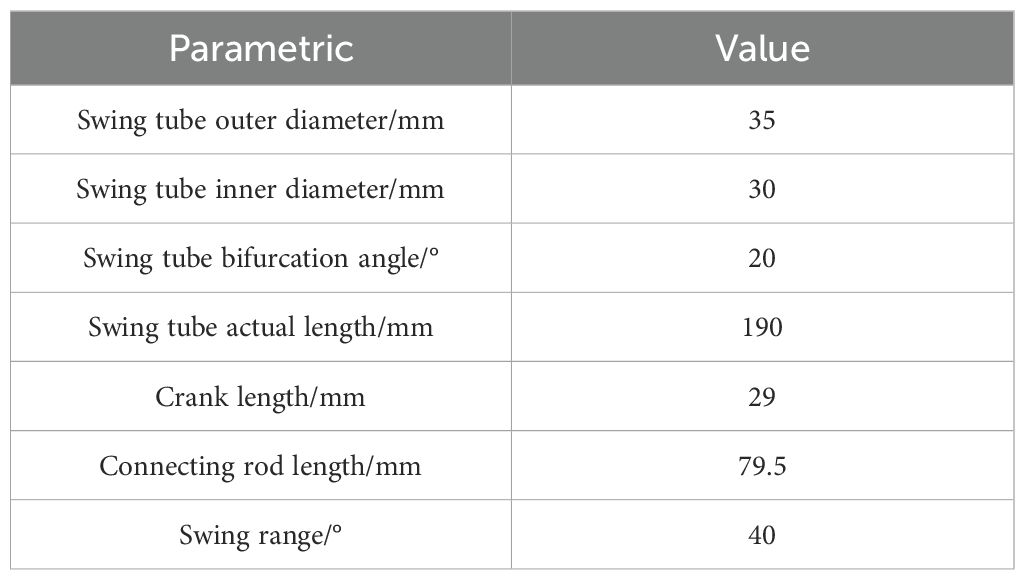
The A and B fertilizer divider tubes are placed at an angle to each other, and the fertilizer flows out of the main tube. Driven by the spatial hammer crank mechanism, the single tube swings in a double area within the spreading range and has an intersection and overlap in the middle of the area so that the total amount of fertilizer can be spread in diverted strips. A lower limit of fertilizer spreading width of 60 cm was used as the basis for the design (He et al., 2021; Zhao et al., 2021a; Gou et al., 2022) and was affected by the combined effect of the size of the machine, the material used for processing, and the comfort of use. Main working parameters of the bifurcated swing tube device are shown in Table 1.
3.4 Fertilizer spreading force analysis
The bifurcated swing tube fertilizer spreading device is made of fertilizer particles discharged from the fertilizer discharge opening by the fertilizer discharger, which naturally falls into the swing tube by gravity. Moreover, the swing tube adopts the principle of the most rapid curve design; therefore, it sprinkles the field in the form of a parabola from the mouth of the swing tube, as shown in Figure 7A, in which the actual length of the swing tube is set to l.
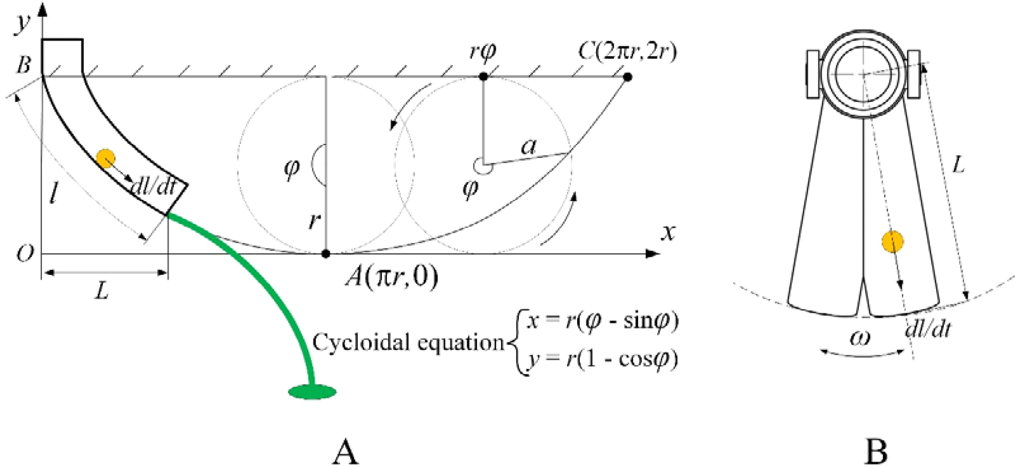
Figure 7. Velocity analysis schematic diagram. (A) Velocity analysis section view of the maximum velocity curve. (B) Velocity analysis plan for fertilizer particles in a tube.
To investigate the equation of motion of the fertilizer particles, it is necessary to know the velocity at which the fertilizer particles leave the mouth of the swing tube, as shown in Figure 7B. When the bifurcated swing tube swings left and right with an angular velocity of ω, fertilizer particles move to the mouth of the swing tube; the velocity is synthesized to obtain the velocity v at this point, which is given by Equation 12.
The length of the swing tube l is equal to the length of the pendulum line of a circle of radius r rolling at a certain angle φ. Knowing the cycloidal equation, the length of the cycloidal l can be found using the following equation.
Substituting Equation 13 into Equation 12 yields:
Because the fertilizer particles undergo parabolic motion with an initial velocity v, and when the throwing speed and the tube mouth height changes, the effect of spreading fertilizer also changes. Therefore, the horizontal and vertical distances of fertilizer particles thrown are studied, the initial velocity v is decomposed into plane velocity v0 and vertical velocity v1, and the oxyz spatial right-angled coordinate system is established with the center of the bifurcated swing tube as the coordinate origin. The movement of fertilizer particles in the air and the forces applied to them are shown in Figure 8.
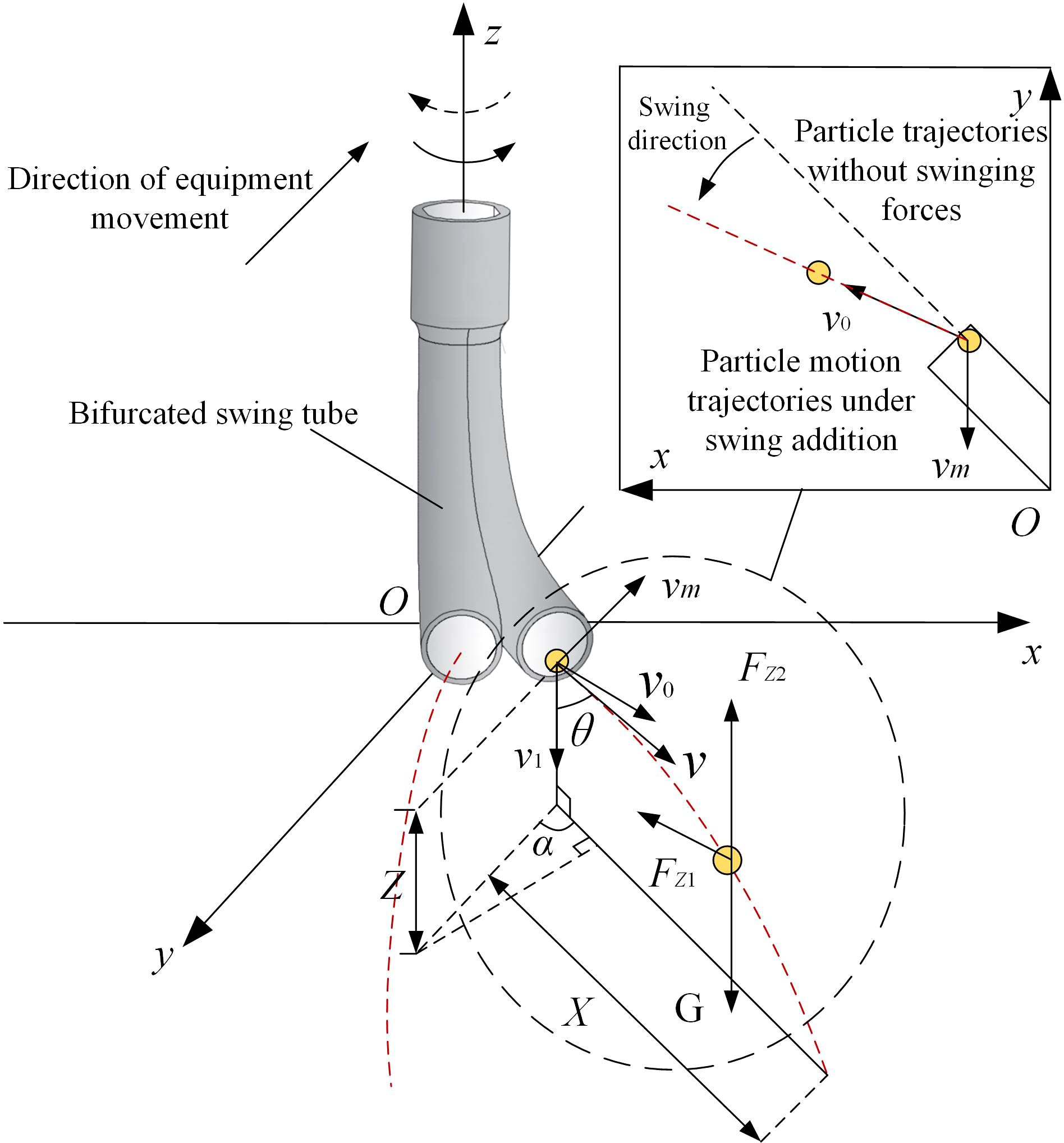
Figure 8. Motion and force analysis of fertilizer particles in air. Note: vm is the forward velocity of the device (m/s) and Z is the nozzle height (mm).
It is assumed that the self-rotation of the fertilizer particle and the airborne wind speed are ignored. Fertilizer particles moving in the air will be subjected to gravity and drag, and free fall along the direction of the nozzle tends to tilt the trajectory in the direction of the swing velocity. The force acting on the fertilizer particles in the air is shown by Equation 15 from the air resistance coefficient equation.
where Fz is the air resistance of the fertilizer particle during their movement (N), c is the coefficient of air resistance of the fertilizer particle and was determined to be c = 0.44 (Tian et al., 2023), s is the area of the wind resistance region of the fertilizer particle (m2), ρa is the air density (kg/m3), and v is the fertilizer particle velocity (m/s).
According to Newton’s second theorem, the force balance equations for the movement of fertilizer particles in the plane and vertical directions are shown in Equations 16 and 17.
where v0 and v1 are the horizontal and vertical partial velocities of the fertilizer particle in motion, respectively (m/s), Fz1 and Fz2 are the horizontal and vertical components of the air resistance on the fertilizer particles during their movement respectively (N), , s = πL2, and ρp is the density of the fertilizer particle (kg/m3).
The differential equation is formed from Equations 15 and 16.
Let be the scale factor. As the machine moves in the opposite direction to the direction of the fertilizer throw, v0 = vsinθ - vmcosα and v1 = vcosθ. Expressions for the distance X in the plane of the throw and the vertical fall distance Z can be derived.
where θ is the angle between the velocity of the fertilizer particle and the vertical component velocity (°), and α is the angle between the horizontal partial velocity of the fertilizer particle and the velocity of the device moving in the opposite direction (°).
Combining the above substitutions yields the trajectory equation for the fertilizer application process.
From the above comprehensive analysis, it can be seen that when the proportionality coefficient j is specific, the landing position of the bifurcated fertilizer spreading device is mainly determined by the dynamic parameters of the nozzle height Z, the forward velocity vm of the device, and the angular velocity ω. The relationship of ω = 2πf is known. The subsequent study can be regarded as the swing tube frequency f as the influence of the dynamic parameters of the fertilizer spreading device on the fertilizer spreading effect. Therefore, in this study, the dynamic parameters of the fertilizer spreading device are firstly optimized through simulation tests by taking the nozzle height Z, the forward velocity vm, and the swing frequency f as the test factors and improving the uniformity of the fertilizer spreading effect as the optimization criterion. Finally, a bench test was conducted to verify whether optimizing the different dynamic parameters could improve the uniformity of fertilizer spreading.
4 MBD-DEM coupled simulation analysis
The dynamic parameters in the action of the fertilizer spreading device have a direct influence on the uniformity of fertilizer spreading, and to clarify the fertilizer spreading characteristics of the bifurcated swing tube, it is proposed that the discrete element method (DEM) will be used for the simulation. However, in fertilizer spreading by a bifurcated swing tube, the presence of a spatial hammer pendulum crank mechanism makes it difficult to realize the actual movement condition of the spatial mechanism in the working environment in EDEM. Therefore, a coupled multibody dynamics-discrete element (MBD-DEM) simulation is used for the analysis. Accurate results are obtained for the kinetic behavior of the particles in the system and the calculation of the forces acting on the particles in the dynamic system (Shi et al., 2022; Deng et al., 2024; Wang et al., 2021).
4.1 Multibody dynamics simulation establishment
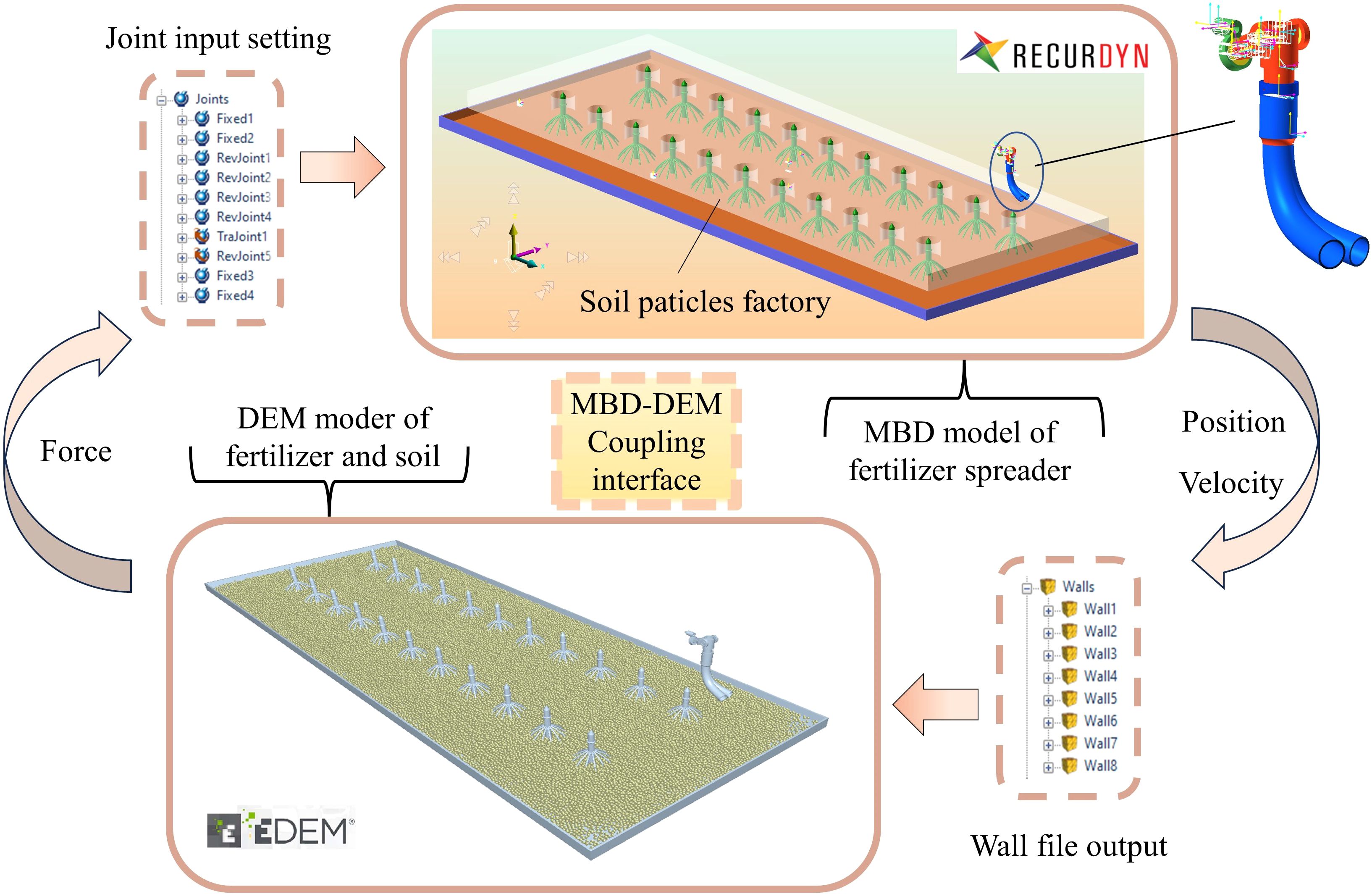
RecurDyn is suitable for solving large-scale complex multibody system dynamics problems. Owing to the complex motion of the bifurcated swing fertilizer spreading device, its simplified geometrical model is established through SolidWorks. An x-t format file is imported into RecurDyn and constraints, contacts, and other attributes are added to build a multi-body dynamics model. The components of the fertilizer spreading device were imported into EDEM as wall files through RecurDyn’s built-in coupling interface to create a discrete element model. The maize single-row planting standard is used as an example to simulate the field operation situation. The simulation model consists of a fertilizer spreading device, a fertilizer particles factory, crops, soil ground, and a soil particles factory. The distance between the crop rows is 600 mm, the nozzle height from the ground is 450.0 mm, the motor drive speed is 90 rpm (the swing tube swing frequency is 1.50 Hz), and the fertilizer spreading device moves with a velocity of 0.5 m/s. The velocity and position of the critical components are controlled by calculating Recurdyn’s equations of motion, and the data are transferred to EDEM through the coupled interface software Recurdyn for co-simulation to analyze the motion process of particle collision, as shown in Figure 9.
4.2 Multibody dynamics simulation establishment
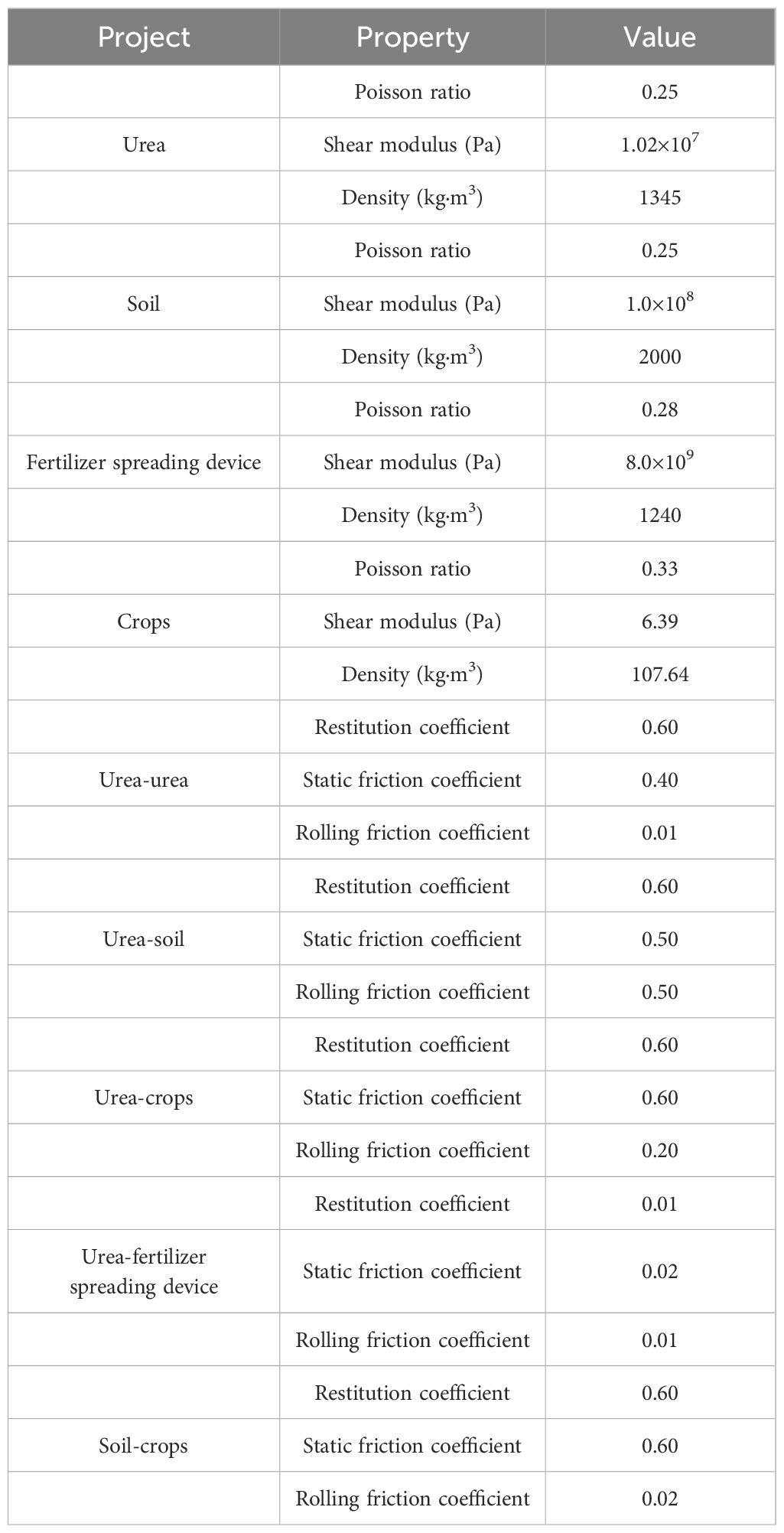
The test fertilizer was selected from urea produced by the Shanxi Shanhua Coal Chemical Industry Group Co. The measured equivalent diameter averaged 1.16 mm, with a sphericity greater than 90%. As the fertilizer is thrown to the ground and comes into contact with the soil and crops during the actual spreading operation, the ground with soil particles is set up to give soil properties to restore the actual contact state of the fertilizer with the soil and crops. The Hertz–Mindlin with the JKR model was used for soil particles to soil particles (Li et al., 2023), whereas Hertz–Mindlin (no-slip) was used as a contact model for urea to urea, urea to the soil, and soil to crop (Zhao et al., 2023). Referring to the related literature (Dun et al., 2023b; Zhao et al., 2021b; Song et al., 2023b), the relevant parameter settings of the simulation model are shown in Table 2.
4.3 Coupling simulation
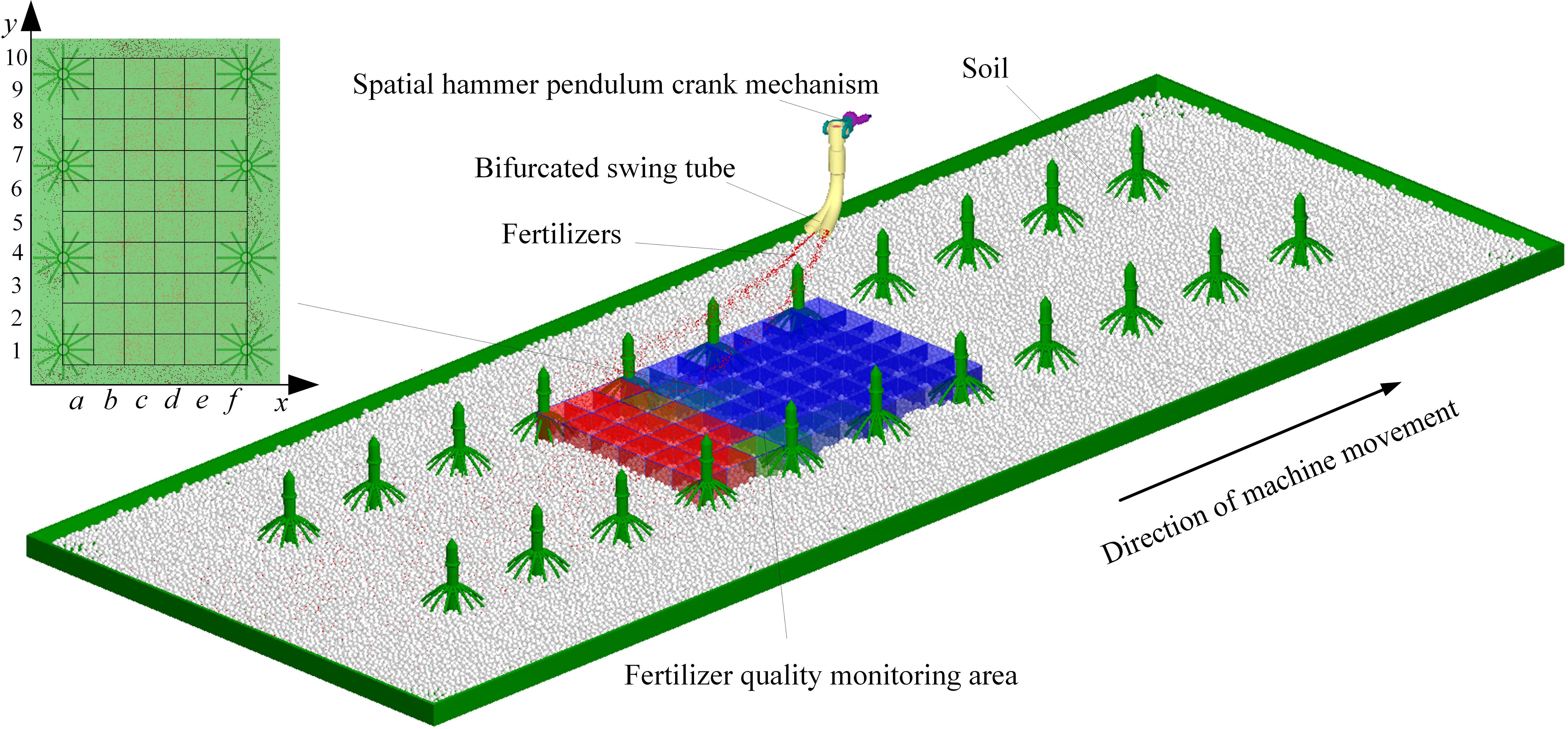
The swing tube fertilizer spreading device and the land components were imported into EDEM as a wall file through RecurDyn’s inbuilt coupling interface to create a discrete metamodel. The soil was simplified to spherical particles, set to a radius of 7 mm, and the soil particle factory was set to generate 90,000 soil particles so that they would naturally spill onto the land collection plate. When the soil is spread over the land collection plate, the fertilizer particles factory is synchronized with the bifurcated fertilizer spreading tube at equal velocity. The fertilizer pellet plant is set to generate 5,000 urea particles per second so that they are thrown to the soil surface with the swing of the bifurcated fertilizer spreading tube, and a fertilizer quality monitoring zone is set up at the soil surface, as shown in Figure 10.
4.4 Fertilizer spreading performance evaluation criteria
To accurately evaluate the uniformity of the bifurcated swing tube when spreading fertilizer, the performance was statistically and analytically analyzed using the grid method (Sugirbay et al., 2020; Wang et al., 2023b) at the end of the coupled simulation. The plant spacing direction y is defined as the longitudinal direction and the ridge spacing direction x as the transversal direction. As the fertilizer spreading device has the same movement pattern for each fertilizer spreading cycle, a fertilizer quality testing area with a length of 1,000 mm, a width of 600 mm, and a height of 300 mm for two cycles of fertilizer spreading is set up on the ground surface. Dividing six portions on x labeled with the letters a to f and ten portions on y labeled with the numbers 1 to 10 makes fertilizer quality monitoring in each cell possible.
Referring to the relevant literature (Zhang et al., 2018; Fan et al., 2024; Zhou et al., 2024), it is known that the evaluation index of fertilizer spreading uniformity is the uniformity coefficient. Fertilizer quality was selected for monitoring areas and measured for unit fertilizer quality monitoring simultaneously. The longitudinal and transverse homogeneity coefficients are calculated according to Equation 21, expressed as Y1 and Y2, respectively. The smaller the uniformity coefficient, the more uniformly the fertilizer is spread and vice versa.
where σ is the uniformity coefficient of fertilizer spreading (%), Sd is the standard deviation of the mass within the cell grid (g), is the average mass within the grid of statistical cells (g), mi is the mass of fertilizer particles in the ith grid (g), and n is the number of statistical cells required.
5 Single-factor test
To determine the effects of nozzle height Z, forward velocity vm, and swing tube frequency f on the fertilizer spreading uniformity, a single-factor experimental study was carried out using an MBD-DEM coupled simulation under different factor variables, and Design-Expert was applied to carry out data processing and statistical analysis (Barbosa, 2020; Bai et al., 2021; Wang et al., 2024).
5.1 The effect of nozzle height Z on fertilizer spreading uniformity
The theoretical analysis shows that the nozzle height Z determines the spreading distance X and thus affects the spreading range W. At the same time, the longitudinal and transversal uniformity coefficients will also change with Z. Therefore, to investigate the effect of nozzle height Z on the uniformity of fertilizer spreading, a single-factor test was conducted with Z as the test factor and longitudinal and transversal uniformity coefficients as the test indexes. By reviewing the relevant literature (He et al., 2021; Zhao et al., 2021), the range of fertilizer spreading height Z was determined to be 250.0 mm < Z < 450.0 mm based on the height of the implement and agronomic characteristics and the design requirements of the fertilizer spreading machinery. Therefore, the test fixed swing tube pendulum frequency f = 1.50 Hz and the forward velocity of the device vm = 0.5 m/s selected the spreading of fertilizer height Z for 250.0 mm, 300.0 mm, 350.0 mm, 400.0 mm, and 450.0 mm for a single-factor test. The coefficient of longitudinal and transversal uniformity and the change trend are calculated in Figure 11A.

Figure 11. Impact curve of the single-factor test. (A) The effect of nozzle height Z on fertilizer spreading uniformity. (B) The effect of forward velocity vm on fertilizer spreading uniformity. (C) The effect of swing frequency f on fertilizer spreading uniformity.
The longitudinal and transversal homogeneity coefficients showed a decreasing and then increasing trend with increasing height Z. A decreasing trend was observed before 400.0 mm, and an increasing trend was observed after 400.0 mm. The images show that after 350.0 mm, the trends of the two curves move differently, with a smaller uniformity coefficient indicating better fertilizer spreading performance. Therefore, 350.0 to 450.0 mm was selected to carry out further studies in conjunction with the effect of other factors on longitudinal and transversal uniformity.
5.2 The effect of machine forward velocity vm on fertilizer spreading uniformity
The bifurcated swing tube fertilizer spreading device moves on the suspension of the agricultural equipment, and the change of its forward velocity vm will change the initial velocity of the fertilizer throwing, thus affecting the size of the uniformity coefficient of the fertilizer spreading. If the device moves too fast, the fertilizer thrown per unit of time floats in the air for too long, and there are too many uncontrollable factors. The device also operates inefficiently at very low speeds; therefore, it was determined that the effect on the uniformity of fertilizer spreading should be investigated in the range of forward velocity 0.5 m/s < vm < 2.5 m/s. The forward velocities of 0.5 m/s, 1.0 m/s, 1.5 m/s, 2.0 m/s, and 2.5 m/s, the height of the swinging tube at a fixed distance from the ground Z=400.0 mm, and the frequency of swinging f=1.50 Hz were set to carry out a single-factor test on the effect of forward velocity vm on the uniformity of fertilizer spreading. The trends are shown in Figure 11B.
The uniformity coefficient of the longitudinal and transversal spreading of fertilizer increases with increasing forward velocity. The image at 1.5 m/s to 2.0 m/s slope is the smallest, adhering to the selection of a smaller uniformity coefficient as the best criterion for determining the range of values of the forward velocity of the machine in the range of 0.5 m/s to 2.0 m/s.
5.3 The effect of swing frequency f on fertilizer spreading uniformity
Based on the above theoretical analysis, the bifurcated swing tube swing frequency f affects the fertilizer spreading effect, hence the uniformity variation. As the spatial crank rotates around the input shaft for 1 week, the bifurcated swing tube swings back and forth from side to side for one cycle. Therefore, the drive speed is too fast, affecting the stability of the spatial hammer pendulum crank mechanism. If the speed is too low, then the bifurcated swing tube swing frequency is too low, and the process of moving implements leads to the swing cycle displacement being too long and cannot be applied to the crop in place. Therefore, a suitable swing frequency range of 0.80 to 2.00 Hz was taken to study the relationship with the uniformity of fertilizer spreading. The swinging frequency of the swing tube was set at 0.80 Hz, 1.10 Hz, 1.40 Hz, 1.70 Hz, and 2.00 Hz to carry out a comparative single-factor test of fertilizer spreading uniformity, in which the height of the limiting nozzle was 400.0 mm and the velocity of advancement was 0.5 m/s.
The trend is shown in Figure 11C, in which the overall uniformity coefficient of longitudinal and transversal fertilizer spreading decreases as the frequency of bifurcated swinging tube swinging increases simultaneously. Therefore, to take the condition that the uniformity coefficient of fertilizer spreading is minimized, it was determined that the swing frequency of the subsequent test was taken in the range of 1.40 to 2.00 Hz.
6 Response surface test
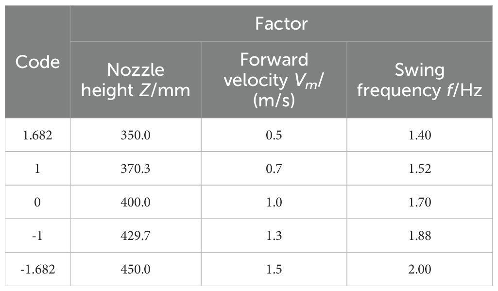
Based on the results of the above single-factor tests, a nozzle height range of 350.0 to 450.0 mm, a forward velocity of 0.5 to 1.5 m/s, and a swing frequency of 1.40 to 2.00 Hz were selected for the ternary-secondary universal rotary combination test conducted in this study. The factor level coding is provided in Table 3.
6.1 Test results and analyses
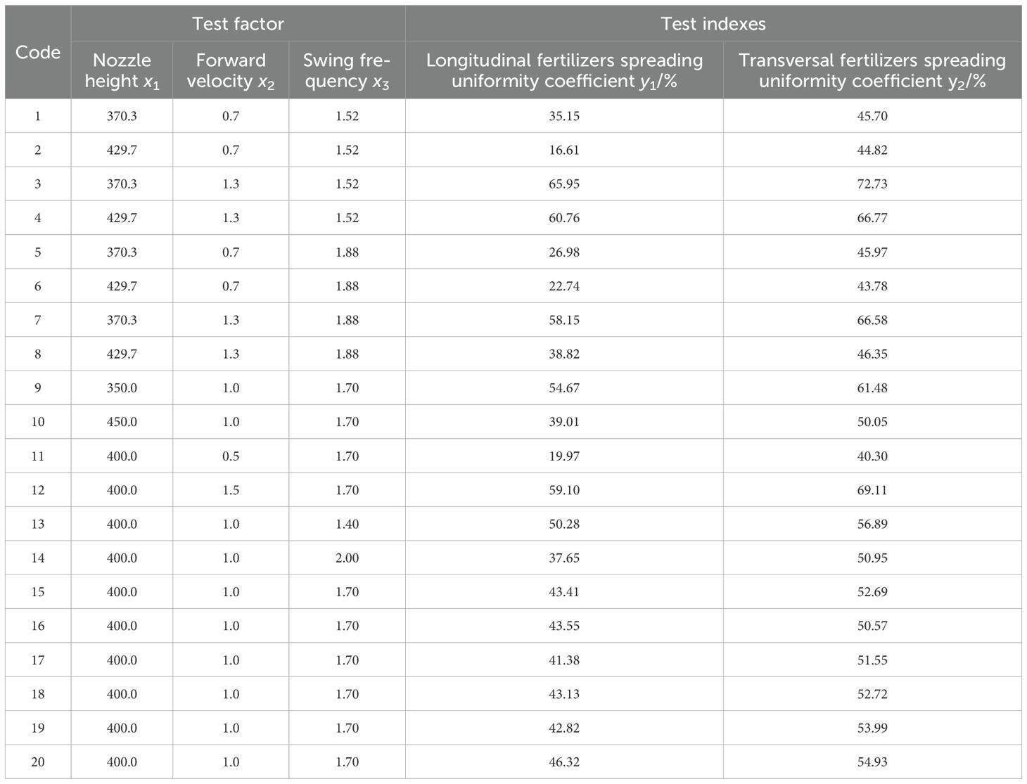
The experiment results are shown in Table 4, in which the factor-coded values are expressed as x1, x2, and x3, and the uniformity coefficients of longitudinal and transversal fertilizer spreading are expressed as y1 and y2, respectively.
6.2 Variance analysis
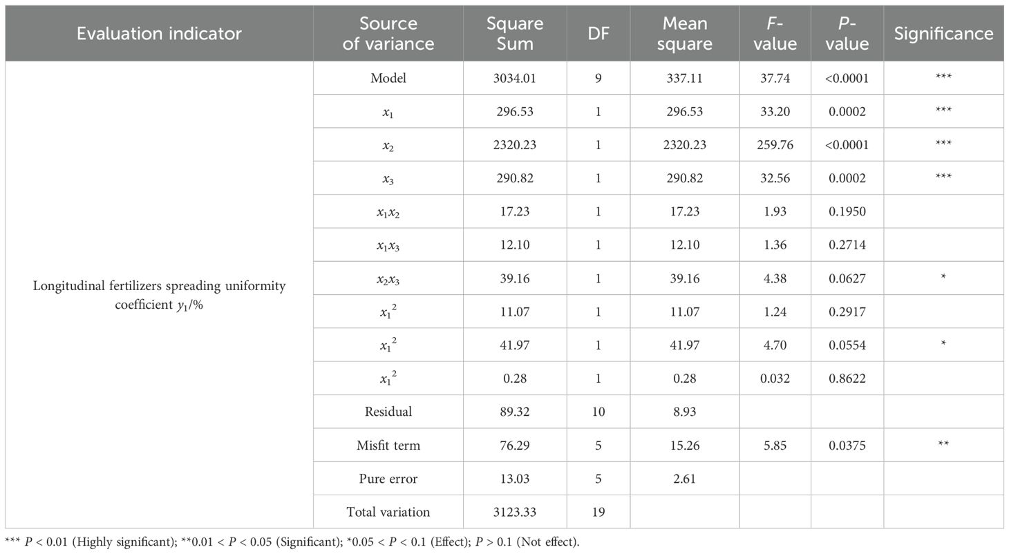
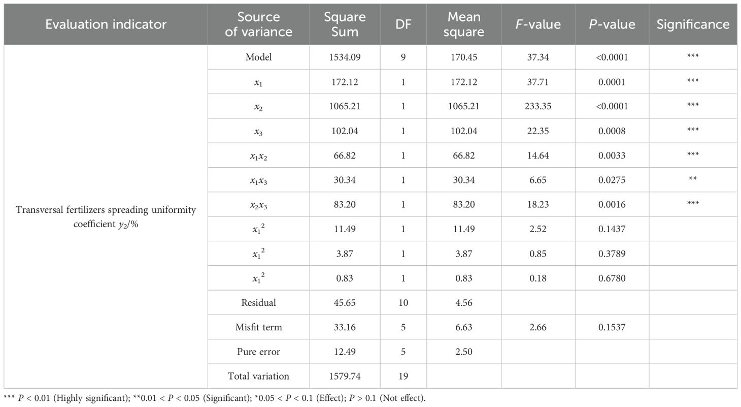
Multiple regressions were fitted to the experimental data to obtain regression equations for longitudinal and transversal fertilizer spreading uniformity coefficients. The analysis of variance (ANOVA) of the model is shown in Tables 5 and 6. The regression model significance tests for longitudinal and transversal fertilizer spreading uniformity coefficients were highly significant (P<0.01). The results of the misfit term test for the uniformity coefficient of longitudinal fertilizer spreading were significant (0.01 < P < 0.05), and the results of the misfit term test for the uniformity coefficient of transversal fertilizer spreading had no effect (P > 0.1). This shows that both regression models fit well in the experimental range.
For the coefficient of longitudinal fertilizer spreading uniformity, x1, x2, and x3 had a highly significant effect on the equation (P < 0.01), x2x3 and x22 affected the equation (0.05 < P < 0.1), and the rest of the terms did not have an effect on the equation (P > 0.1).
For the uniformity coefficient of transversal fertilizer spreading, the effect of x1, x2, x3, x1x2, and x2x3 on the equation was highly significant (P < 0.01), the effect of x1x3 on the equation was significant (0.01 < P < 0.05), and the rest of the terms had no effect on the equation (P > 0.1).
Removing the uninfluenced factors from the regression equation, the regression equation of the factors with the coefficients of uniformity of longitudinal and transverse fertilizer spreading can be known.
6.3 Response surface analysis
The effect of each factor on the uniformity coefficient of fertilizer spreading in each longitudinal and transversal direction is shown in Figure 12. The nozzle height setting x1 for bifurcated swing tube fertilizer spreading is closely related to the longitudinal fertilizer spreading uniformity y1 coefficient, as shown in Figure 12A. It can be concluded that as x1 increases, y1 decreases gradually. Therefore, based on the maximum value of the nozzle height x1 = 450.0 mm, the response surface plot of the effect of the forward velocity x2 and the swing frequency x3 on the coefficient of longitudinal fertilizer spreading uniformity y1 is established, as shown in Figure 12B. As x2 increases, y1 increases significantly, and as x3 increases, y1 decreases. The y1 trend is highest at a low swing frequency and high speed because, in this case, the longitudinal distance of fertilizer application is too long when the swing tube swings at a unit angle, resulting in less coverage of the surface area passed by the fertilizer application path for the same swing amplitude, and less application over a long swing period. Under conditions of high swing frequency and low travel velocity, y1 tends to be lowest so that short swing periods with many application volumes occur, and fertilizer application paths can be multiplexed to cover the surface through which it passes.
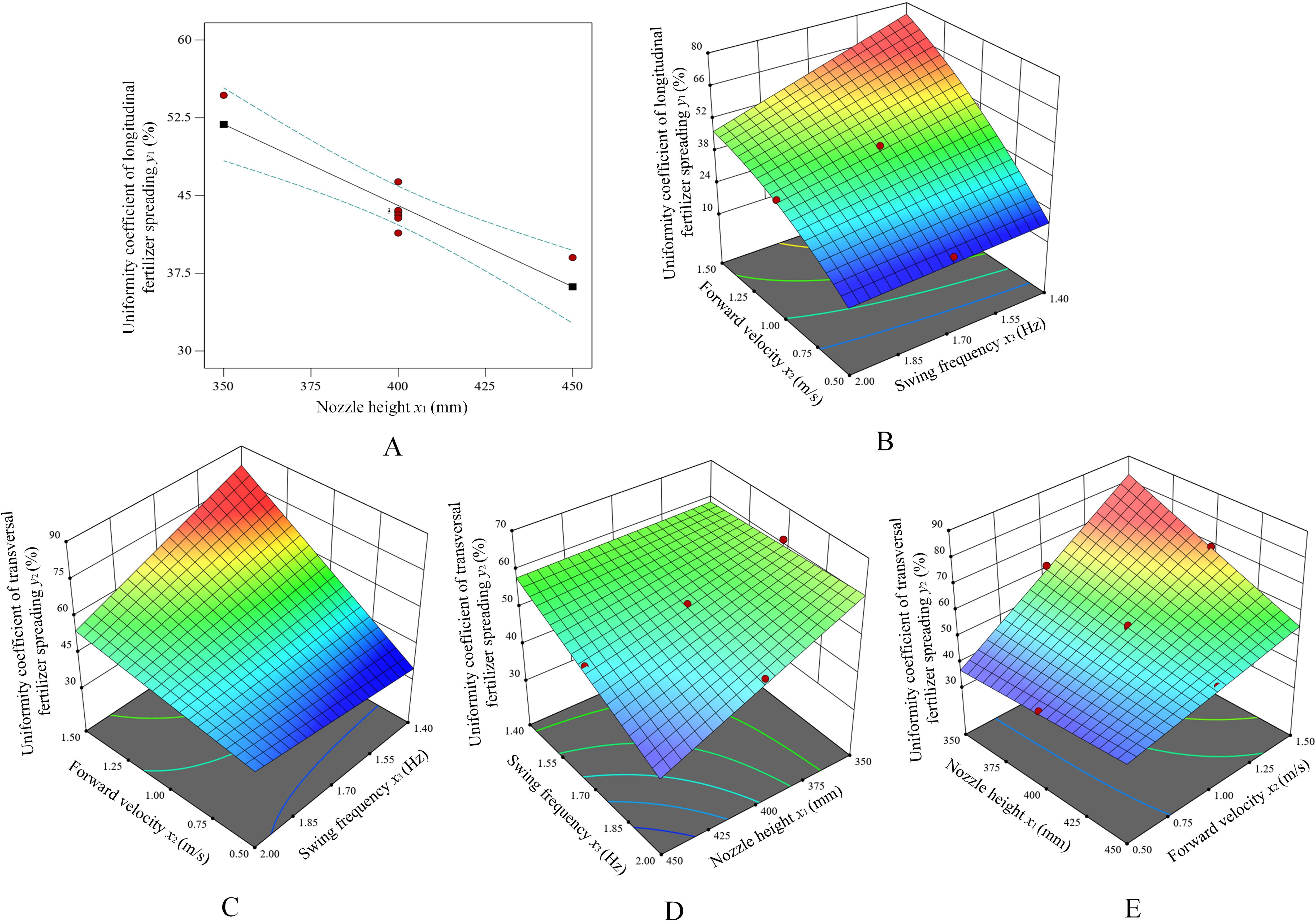
Figure 12. The effect of experimental factors on the uniformity coefficient of longitudinal and transversal fertilizer spreading. (A) The effect of x1 on y1. (B) The effect of the interaction of x2 and x3 on y1. (C) The effect of the interaction of x2 and x3 on y2. (D) The effect of the interaction of x3 and x1 on y2. (E) The effect of the interaction of x1 and x2 on y2.
Analysis of the response surface plot in Figure 12C shows that the uniformity coefficient of the lateral spreading of fertilizer y2 increases with the increase in the velocity of movement when x3 is low. x2 is low. The change in x3 does not have a significant effect on y2. The reason for this is that at high traverse velocities and low swing frequencies, the path of the fertilizer application does not effectively cover the surface through which it passes. Within the lateral width of the application per unit traveling distance, the amount of fertilizer at the extremes of the swing is low, resulting in a large number of “blank” unapplied areas and, therefore, an uneven lateral spreading of fertilizer. Analysis of Figure 12D reveals that y2 has minimal impact on the trend observed when both x1 and x3 are set to high values. Moreover, the response surface plot tends to decline in the lowest parameter of x1 and x3, and y2 is minimum when x1 and x3 are minimum values. From the analysis in Figure 12E, it is clear that x1 is low and y2 increases as x2 increases. x2 is low, and the change in x1 is not significant for y2, as the uniformity of fertilizer spreading is better because the fertilizer is fully applied to the surface in low shift velocities, which increases the fertilizer coverage on the surface.
6.4 Parameter optimization
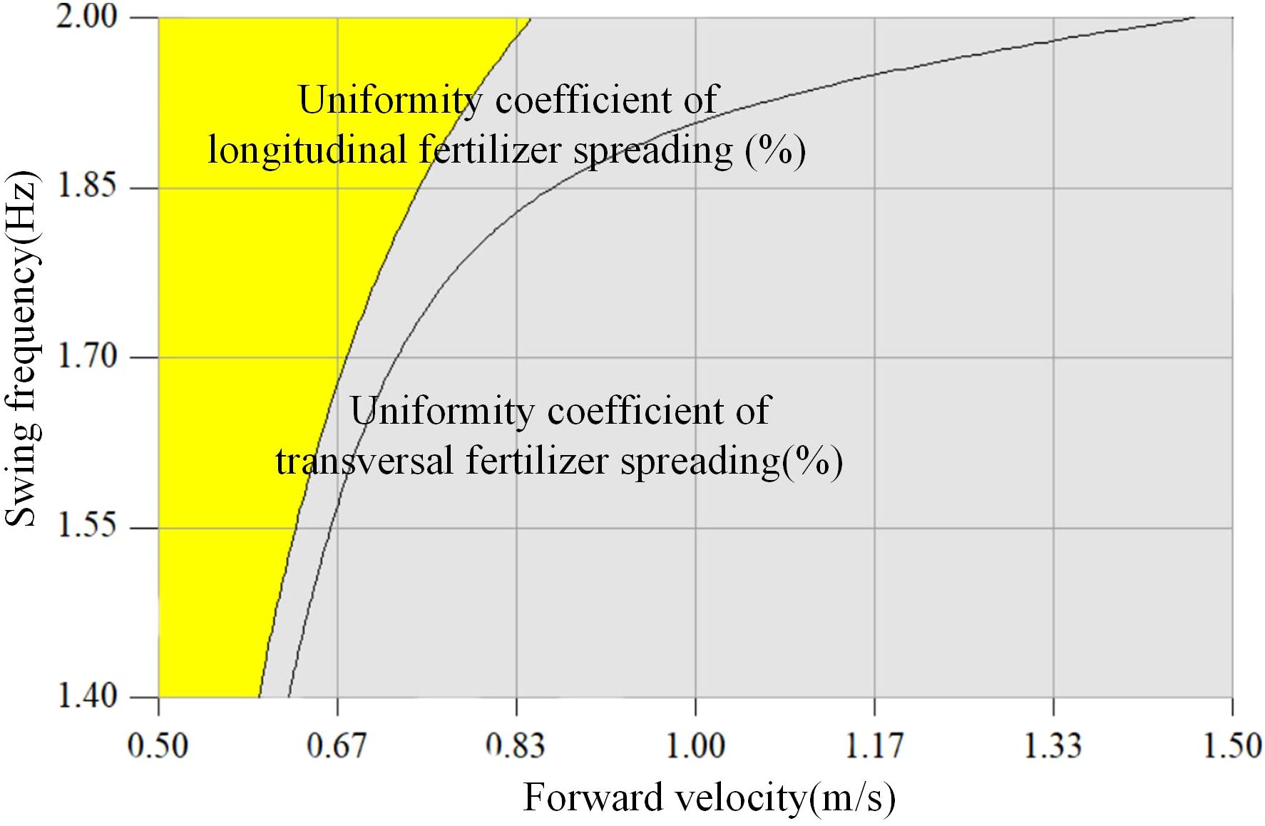
The uniformity coefficient of fertilizer spreading derived from the test should be based on the referenced NY/T1003-2006 Technical Specification for Quality Evaluation of Fertilizer Application Machinery (NY/T 1003-2006). To find the optimal combination of the relevant factors, it was determined that the nozzle height x1 = 450.0 mm, which gives the minimum value of the uniformity coefficient of longitudinal and transversal fertilizer spreading, should be the basis for optimizing the parameters. The smaller the uniformity coefficient of longitudinal and transversal spreading, the more uniformly the fertilizer is applied; therefore, the uniformity coefficient of longitudinal spreading is set to ≤25%, and the uniformity coefficient of transversal spreading is set to ≤45%. The optimization equations are shown in Equation 23 using Design-Expert software with multi-objective optimization (Liu et al., 2024; Wang et al., 2023) and the solved parameter ranges as constraints.
Based on the above optimization Equation 23, the best optimization region for the forward velocity x2 and swing frequency x3 is obtained, as shown in the yellow shaded area in Figure 13. The optimized intervals are a forward velocity of 0.5–0.8 m/s and a swing frequency of 1.40–2.00 Hz.
The coupled simulation model was established to determine that the fertilizer spreading device meets the optimal fertilizer spreading effect by selecting the nozzle height x1 = 450.0 mm, the forward velocity x2 = 0.55 m/s, and the swinging frequency x3 = 1.60 Hz. Simulation tests were carried out to verify the coefficients of the longitudinal and transversal fertilizer spreading uniformity of the dynamic parameters of the bifurcated swing tube fertilizer spreading device. The uniformity coefficients of longitudinal and transversal fertilizer spreading were obtained as 40.98% and 22.73% for the simulation validation values, respectively. The correctness of the optimization results is verified, and the data are analyzed below in comparison with the bench test data.
7 Bench test
7.1 Design of the experiment
To verify the correctness of the optimized parameters and the feasibility of the MBD-DEM coupled simulation verification experiment, the bifurcated swing tube fertilizer spreading device was machined and assembled, and the fertilizer spreading experiment platform was constructed. Bench experiments were conducted in May 2024 outside the Intelligent Agricultural Machinery and Equipment Engineering Laboratory at Harbin Cambridge College. According to the method of dividing the grid statistics of fertilizer distribution in the coupled simulation test, ten rows and six columns of 10 cm × 10 cm × 10 cm open square boxes are set up in the 60 cm × 100 cm test area with a total of 60 fertilizer collection points, to realistically restore the statistical area of the coupled simulation in the way of actual grid division. The fertilizer was selected from urea fertilizer produced by the Shaanxi Shanhua Coal Chemical Industry Group Co. The speed of the fertilizer discharge wheel of the fertilizer discharger used in the experiment was set at 60 r/min. The automatic lifting device controls the nozzle height from the ground at 450.0 mm, the swinging frequency of the swinging tube is 1.60 Hz, and the whole machine is towed by the power unit to control the forward velocity of the machine tool at 0.55 m/s. The control system selects the intelligent fertilizer controller produced by the Tripartite Agricultural Machinery Company, and the battery selects the 6-DZF-12 lead-acid battery model.
Before the start of the experiment, the bench unit is positioned on the start line in the middle of the experiment boxes. After the bifurcated swing tube fertilizer spreading unit has been operated, the traction unit pulls the bench along the center line of the experiment grid. At the end of the experiment, the fertilizer in each collection box was filled up using collection bags. Once all the fertilizers were collected, the above experiment was repeated three times. Labeling each collection bag with collected fertilizer in the appropriate location makes it easy to count the results of the different location experiments. Each bag of experiment fertilizer was weighed with an electronic weighing scale and the husk was removed as it was weighed, as shown in Figure 14.
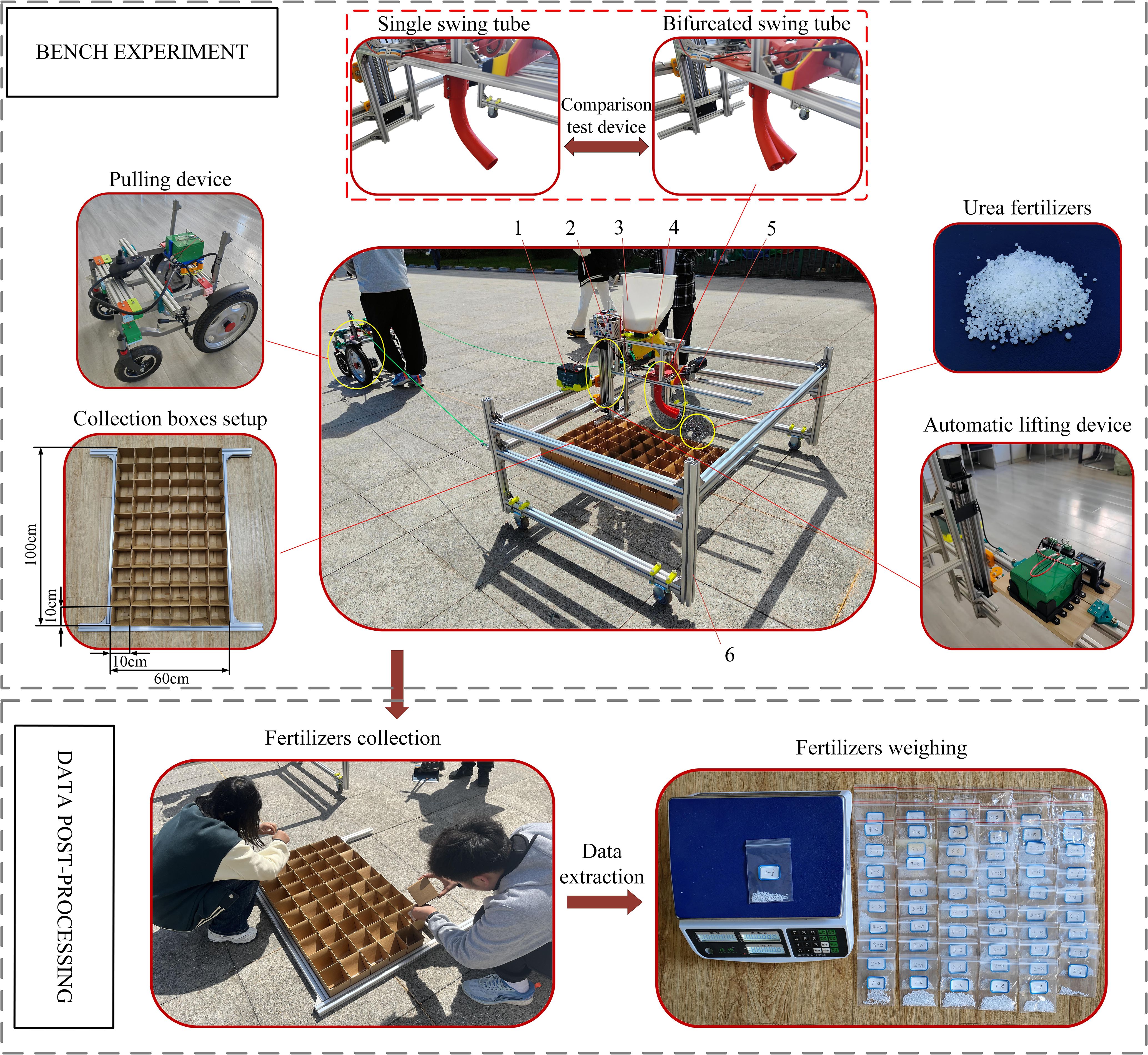
Figure 14. Bench validation and comparison experiment setup and post-processing. 1. Battery. 2. Motor controller. 3. Fertilizers tank. 4. Fertilizer discharger. 5. Drive motor. 6. Experimental bench.
7.2 Comparative experiment
To further determine the fertilizer spreading advantages and disadvantages of a bifurcated swing tube over a single swing tube. Under the condition of the same nozzle height, swinging frequency and forward velocity, replace the single swing tube (the parameters of the single swing tube are the same as those of the bifurcated swing tube) to carry out the comparison test. The data from the simulation verification experiment and the comparison test were recorded, and the experiment results are shown in Table 7.
By comparing the bench experiment data with the simulation data, the relative error of the longitudinal fertilizer spreading uniformity coefficient of the bench experiment was 3.46%, and the relative error of the transversal fertilizer spreading uniformity coefficient with the simulation experiment was 1.44%. The validation experiment was in general agreement with the simulation experiment, resulting in an error that could be due to the difference in the amount of fertilizer applied by the fertilizer discharger. By comparing the experimental data, the uniformity coefficient of the longitudinal fertilizer spreading of a bifurcated swing tube was reduced by 50.33%, and the uniformity coefficient of transversal fertilizer spreading was decreased by 14.95% compared with that of a single swing tube. The number of broken fertilizer particles in the bench experiment was minimal, and the broken particles were residual particles. The study can provide a reference for the optimal spiral fertilizer discharger design.
To verify the reasonableness and accuracy of the test, a three-dimensional distribution map of overlapping fertilizer particles was plotted based on the bench comparison experiment data, as shown in Figure 15. It can be seen that the difference between the peak and the trough of the distribution of single swing fertilizer is significant, with some higher and lower sharp points, which is due to the effect of “one more, one less” staggered by the swing of the single swing tube structure. Although the bifurcated swing tube has a better fertilizer spreading distribution than the single swing tube, as can be seen from the contour map color, the dark blue color shows almost nothing, which can be proven to be a better fertilizer spreading balance in the unit area. The spreading uniformity coefficient of total fertilizer was calculated using Equation 21 and was 48.53% for a single swing tube and 38.12% for a bifurcated swing tube. It is proved that the bifurcated structure swing tube device spreads fertilizer evenly with good effect and meets the standard of fertilizer discharge performance of fertilizer application machinery specified in the referenced (NY/T1003-2006, 2015) Technical Specification for the Quality Evaluation of Fertilizer Application Machines (NY/T 1003-2006), which improves the utilization rate of fertilizers and promotes the sustainable development of agriculture. This study can be used as a theoretical reference for the design of a swing tube fertilizer spreading device.

Figure 15. Fertilizer particle distribution with different swing tube spreaders. (A) Bifurcated swing tube fertilizer spreading distribution. (B) Single swing tube fertilizer spreading distribution.
8 Conclusion
1. In this study, to address the uneven spreading of fertilizer by a swing tube, a bifurcated swing tube fertilizer spreading device was designed based on the principle of the most rapid curve through the spatial hammer pendulum crank mechanism drive combined with the fertilizer discharger. The design of a spatial hammer pendulum crank mechanism based on a cylindrical pair achieves a change from a rotation to a swing, and the optimization of a bifurcated pendulum tube is based on the cycloidal equation. The influence of the dynamic parameters, such as the nozzle height, the forward velocity of the machine, and the swinging frequency of the swing tube, on the fertilizer spreading effect was theoretically analyzed, and the MBD-DEM coupled simulation model was established by using RecurDyn and EDEM.
2. The range of values of the parameters of each experiment factor was determined through a single-factor experiment, and a ternary two general-purpose rotary combination simulation experiment was designed using the uniformity coefficients of longitudinal and transversal fertilizer spreading as the experimental indexes. The relationship between the changes in the effects of the experiment’s factors on the experiment’s indicators was derived from the established regression models for the coefficients of longitudinal and transversal fertilizer spreading uniformity. The results showed that the effects of each experiment factor on each experiment index were highly significant and optimized to yield a longitudinal fertilizer spreading uniformity coefficient of less than 25% and a transversal fertilizer spreading uniformity coefficient of less than 45% when the nozzle height was 450.0 mm, the swing frequency was 1.50-2.00 Hz, and the operating velocity was within the range of 0.5-0.8 m/s.
3. Simulation and bench validation experiments were carried out under the optimal parameter combinations, and the experimental results agreed with the simulation results. The deviation values of the longitudinal and transversal uniformity coefficients were 1.44% and 3.46%, respectively, which were 50.33% lower than the uniformity coefficients of the longitudinal spreading of fertilizers by a single swinging tube and 14.95% lower than the uniformity coefficients of the transversal spreading of fertilizers. Moreover, the total uniformity coefficient of fertilizer spreading was 38.12%, which is in line with the (NY/T1003-2006, 2015) Technical Specification for the Quality Evaluation of Fertilizer Applying Machines, proving that the bifurcated swinging tube fertilizer spreading device can achieve the purpose of uniformly spreading fertilizers, improve the fertilizer utilization rate, and promote the sustainable development of agriculture.
Data availability statement
The raw data supporting the conclusions of this article will be made available by the authors, without undue reservation.
Author contributions
GD: Conceptualization, Funding acquisition, Methodology, Project administration, Resources, Supervision, Writing – review & editing. QS: Conceptualization, Data curation, Formal analysis, Investigation, Writing – original draft. XJ: Investigation, Validation, Writing – original draft. XL: Software, Writing – review & editing. YW: Visualization, Writing – review & editing. SG: Validation, Writing – review & editing. CZ: Software, Writing – original draft.
Funding
The author(s) declare financial support was received for the research, authorship, and/or publication of this article. This project has received funding from the Heilongjiang Province Natural Science Foundation of China, grant number LH2023E025, and the Harbin Cambridge University Key Scientific Research Application Research Project, grant number JQZKY2022021.
Conflict of interest
The authors declare that the research was conducted in the absence of any commercial or financial relationships that could be construed as a potential conflict of interest.
Publisher’s note
All claims expressed in this article are solely those of the authors and do not necessarily represent those of their affiliated organizations, or those of the publisher, the editors and the reviewers. Any product that may be evaluated in this article, or claim that may be made by its manufacturer, is not guaranteed or endorsed by the publisher.
References
Bai, J., Hao, F., Cheng, G., Li, C. (2021). Machine vision-based supplemental seeding device for plug seedling of sweet corn. Comput. Electron. Agric. 188, 106345. doi: 10.1016/j.compag.2021.106345
Bai, Q. W., Luo, H. P., Fu, X. L., Zhang, X., Li, G. L. (2023). Design and experiment of lightweight dual-mode automatic variable-rate fertilization device and control system. Agriculture. 13, 1138. doi: 10.3390/agriculture13061138
Barbosa, L. A. (2020). Modelling the aggregate structure of a bulk soil to quantify fragmentation properties and energy demand of soil tillage tools in the formation of seedbeds. Biosyst. Eng. 197, 203–215. doi: 10.1016/j.biosystemseng.2020.06.019
Cao, L. (2016). Design and experimental study of lime spreader device of rotary cultivator. (Changsha (HN):Hunan Agricultural University).
Chen, M., Liu, X., Hu, P., Zhai, X., Han, Z., Shi, Y., et al. (2024). Study on rotor vibration potato-soil separation device for potato harvester using DEM-MBD coupling simulation. Comput. Electron. Agric. 218, 108638. doi: 10.1016/j.compag.2024.108638
Deng, H., Dai, F., Shi, R., Song, X., Zhao, W., Pan, H. (2024). Simulation of full-film double-row furrow roller hole fertiliser application based on DEM-MBD coupling and research on its water and fertiliser transport law. Biosyst. Eng. 239, 190–206. doi: 10.1016/j.biosystemseng.2024.02.007
Dun, G., Mao, N., Ji, X., Zhang, F., Ji, W. (2023b). Optimal design and experiment of corn-overlapped strip fertilizer spreader. Appl. Sci. 13, 2559. doi: 10.3390/app13042559
Dun, G. Q., Wu, X. P., Ji, X. X., Zhang, F. L., Ji, W. W., Zhu, L. G. (2023a). Design and experiment of corn strip swing tube fertilizer spreader. J. Jilin Univ. (Eng. Technol. Ed.), 1–11. doi: 10.3390/app13042559
Fan, C., He, R., Shi, Y., He, L. (2024). Structure and operation mode of centrifugal side-throwing organic fertilizer spreader for greenhouses. Powder Tech. 438, 119457. doi: 10.1016/j.powtec.2024.119457
Fang, Y., Yang, Y. (2022). Design and analysis of driving mechanism of flapping-wing aircraft based on space crank-swing rod mechanism. J. Shanghai Norm. Univ. (Nat. Sci.) 04, 539–543. doi: 10.3969/J.ISSN.1000-5137.2022.04.020
Gou, Y., Li, H., Wang, D., He, H. (2022). Design and simulation parameter optimization of small intelligent variable fertilizer spreader based on EDEM. J. Agric. Mech. Res. 11), 65–71 + 76. doi: 10.13427/j.cnki.njyi.2022.11.038
He, Y., Zhao, X., Li, C., Dou, H., Li, S., Wang, X. (2021). Research status and analysis on fertilization technology of corn topdressing machinery. J. Agric. Mech. Res. 07), 1–9. doi: 10.13427/j.cnki.njyi.2021.07.001
Hwang, S. J., Nam, J. S. (2021). DEM simulation model to optimise shutter hole position of a centrifugal fertiliser distributor for precise application. Biosyst. Eng. 204, 326–345. doi: 10.1016/j.biosystemseng.2021.02.004
Li, P., Xia, J. F. (2013). Design on general fertilizer spreading machines of swing tube type. Hubei Agric. Sci. 21), 5329–5333. doi: 10.14088/j.cnki.issn0439-8114.2013.21.034
Li, S., Diao, P., Zhao, Y., Miao, H., Li, X., Zhao, H. (2023). Calibration of discrete element parameter of soil in high-speed tillage. Inmateh Agric. Eng. 71, 248–258. doi: 10.35633/inmateh-71-21
Liu, C., Li, Y., Song, J., Ma, T., Wang, M., Wang, X., et al. (2017). Performance analysis and experiment on fertilizer spreader with centrifugal swing disk based on EDEM. Trans. CSAE. 33, 32–39. doi: 10.11975/j.issn.1002-6819.2017.14.005
Liu, H., Xu, W., Yuan, Q., Zeng, J., Lei, X., Lyu, X. (2024). Optimization and experimental study of operation parameters for fertilizer injection drilling device based on discrete element simulation. Appl. Sci. 14, 2642. doi: 10.3390/app14062642
Liu, H., Zhao, Y., Xie, Y., Zhang, Y., Shang, J. (2023). Design and experiment of spiral blades auxiliary roller of organic fertilizer side throwing device. Trans. CSAM. 54, 107–119. doi: 10.6041/j.issn.1000-1298.2023.04.010
NY/T1003—2006 (2015). Technical Specification for Quality Price of Fertilizer Machinery (Beijing, China: China Standards Press).
Peng, M. D., Zhang, Z. G., Zhang, W. Y., Huang, H. X., Zhang, G. C., Liu, W. K., et al. (2023). Design and optimization of sugarcane spiral fertilizer applicator based on response surface methodology and artificial neural networks. Processes. 11, 2881. doi: 10.3390/pr11102881
Shi, L., Zhao, W., Hua, C., Rao, G. G., Guo, J., Wang, Z. (2022). Study on the intercropping mechanism and seeding improvement of the cavity planter with vertical insertion using DEM-MBD coupling method. Agriculture. 12, 1567. doi: 10.3390/agriculture12101567
Shi, Y. Y., Man, C., Wang, X. C., Odhiambo, M. O., Ding, W. (2018). Numerical simulation of spreading performance and distribution pattern of centrifugal variable-rate fertilizer applicator based on DEM software. Comput. Electron. Agric. 144, 249–259. doi: 10.1016/j.compag.23017.12.015
Song, X., Dai, F., Zhang, F. W., Wang, D., Liu, Y. (2023b). Calibration of DEM models for fertilizer particles based on numerical simulations and granular experiments. Comput. Electron. Agric. 204, 107507. doi: 10.1016/j.compag.2022.107507
Song, X. F., Dai, F., Zhang, X. K., Gao, W. J., Li, X. Z., Zhang, F. W., et al. (2023a). Simulation and experiment of fertilizer discharge characteristics of spiral grooved wheel with different working parameters. Sustainability. 15, 11309. doi: 10.3390/su151411309
Sugirbay, A., Zhao, J., Nukeshev, S. O., Chen, J. (2020). Determination of pin-roller parameters and evaluation of the uniformity of granular fertilizer application metering devices in precision farming. Comput. Electron. Agric. 179, 105835. doi: 10.1016/j.compag.2020.105835
Tian, Y., Gong, H., Feng, X., Cai, Y., Zeng, Z., Qi, L. (2023). Development of a model to predict the throwing trajectory of a rice seedling. Comput. Electron. Agric. 211, 108025. doi: 10.1016/j.compag.2023.108025
Wang, F., Dai, F., Zhang, F., Song, X., Shi, R., Zhao, W., et al. (2023). Simulation analysis and test on the effect of picking up the residual film of typical film lifting parts. Agronomy. 13, 488. doi: 10.3390/agronomy13020488
Wang, J., Fu, Z., Jiang, R., Song, Y., Yang, D., Wang, Z. (2023b). Influences of grooved wheel structural parameters on fertilizer discharge performance: Optimization by simulation and experiment. Powder Tech. 418, 118309. doi: 10.1016/j.powtec.2023.118309
Wang, J. F., Wang, R. D., Ju, J. Y., Song, Y. L., Fu, Z. D., Lin, T. H., et al. (2023a). Study on the influence of grooved-wheel working parameters on fertilizer emission performance and parameter optimization. Agronomy. 13, 2779. doi: 10.3390/agronomy13112779
Wang, J., Yao, Z., Xu, Y., Guo, F., Guan, R., Li, H. (2024). Mechanism analysis and experimental verification of side-filled rice precision hole direct seed-metering device based on MBD-DEM simulations. Agriculture. 14, 184. doi: 10.3390/agriculture14020184
Wang, S., Yin, Y., Yu, S., Hou, L. (2021). Dynamic analysis on loader coupling based on RecurDyn-EDEM. J. Mach. Des. 11), 1–6. doi: 10.13841/j.cnki.jxsj.2021.11.002
Wang, X., Zhou, Z., Chen, B., Zhong, J., Fan, X., Hewitt, A. (2024). Distribution uniformity improvement methods of a large discharge rate disc spreader for UAV fertilizer application. Comput. Electron. Agric. 220, 108928. doi: 10.1016/j.compag.2024.108928
Wu, H., Niu, W., Song, Y., Hao, Y., Wang, S., Yan, S. (2023). Motion trajectory design for underwater gliders inspired by brachistochrone. J. Mech. Eng. 1-11. Available at: https://link.cnki.net/urlid/11.2187.TH.20231005.1818.012.
Yang, S., Chen, Z., Ma, Z., Shi, R., Su, W., Bai, Y. (2024). Optimal design of negative pressure chip extraction device based on the theory of the dastest dalling line. Modul. Mach. Tool Auto. Manufac. Tech. 02), 141–145. doi: 10.13462/j.cnki.mmtamt.2024.02.029
Zhan, C. X., Ding, W. Q., Han, Y., Jiang, Q. H., Zhao, Y., Zhao, L., et al. (2023). Design and experiments with a single spiral fixed depth ditching and fertilizing machine. Sci. Rep. 13, 7798. doi: 10.1038/s41598-023-34464-6
Zhang, L. X. (2009). Research and Design on fertilizer spreading machines of swing tube type. (Xianyang (SN): Northwest A&F University).
Zhang, M. Q., Niu, H., Han, Y. C., Zhi, Y., Yuan, T. H., Zhang, H., et al. (2024). A simulation and experiment of the flow fluctuation characteristics of a fertilizer distribution apparatus with a screw from the perspective of the force chain. Appl. Sci. 14, 1122. doi: 10.3390/app14031122
Zhang, L. P., Zhang, L. X., Zheng, W. Q. (2018). Fertilizer feeding mechanism and experimental study of a spiral grooved-wheel fertilizer feeder. J. Eng. Sci. Tech. Rev. 11, 107–115. doi: 10.25103/jestr.116.14
Zhao, S., Gao, L., Yuan, Y., Hou, L., Zhang, X., Yang, Y. (2021b). Maize straw motion law in subsoiling operation using discrete element method. Trans. CSAE. 37, 53–62. doi: 10.11975/j.issn.1002-6819.2021.20.006
Zhao, S., Liu, H., Hou, L., Zhang, L., Zhang, X., Yuan, Y. (2021a). Development of deep fertilizing no-tillage segmented maize sowing opener using discrete element method. Trans. CSAE. 13), 1–10. doi: 10.11975/j.issn.1002-6819.2021.13.001
Zhao, J., Zhao, H., Tang, H., Wang, X., Yu, Y. (2023). Bionic threshing component optimized based on MBD-DEM coupling simulation significantly improves corn kernel harvesting rate. Comput. Electron. Agric. 212, 108075. doi: 10.1016/j.compag.2023.108075
Zhao, L., Zhou, H., Xu, L., Yuan, W., Shi, M., Zhang, J., et al. (2023). Parameter optimization of the spiral fertiliser discharger for mango orchards based on the discrete element method and genetic algorithm. Front. Plant Sci. 14. doi: 10.3389/fpls.2023.1169091
Zhou, H., Yao, W., Su, D., Guo, S., Zheng, Z., Yu, Z., et al. (2024). Application of a centrifugal disc fertilizer spreading system for UAVs in rice fields. Heliyon. 10, e29837. doi: 10.1016/j.heliyon.2024.e29837
Keywords: bifurcated swing tube, strip fertilizer spreading, uniformity, spatial mechanism, MBD-DEM, coupling simulation
Citation: Dun G, Sheng Q, Ji X, Li X, Wei Y, Gao S and Zhang C (2024) Optimization of and experimentation with a bifurcated swing tube strip fertilizer spreading device based on MBD-DEM coupling. Front. Plant Sci. 15:1456173. doi: 10.3389/fpls.2024.1456173
Received: 01 July 2024; Accepted: 04 September 2024;
Published: 04 October 2024.
Edited by:
Yunchao Tang, Dongguan University of Technology, ChinaReviewed by:
Sayantan Sarkar, Texas A&M AgriLife Research, United StatesEgle Jotautiene, Vytautas Magnus University, Lithuania
Copyright © 2024 Dun, Sheng, Ji, Li, Wei, Gao and Zhang. This is an open-access article distributed under the terms of the Creative Commons Attribution License (CC BY). The use, distribution or reproduction in other forums is permitted, provided the original author(s) and the copyright owner(s) are credited and that the original publication in this journal is cited, in accordance with accepted academic practice. No use, distribution or reproduction is permitted which does not comply with these terms.
*Correspondence: Guoqiang Dun, dunguoqiangpatent@163.com; Quanbao Sheng, shengquanbao2024@163.com
 Guoqiang Dun1,2*
 Quanbao Sheng
 Xin Li
 Yuhan Wei