- 1Changchun Institute of Optics, Fine Mechanics and Physics, Chinese Academy of Sciences, Changchun, China
- 2University of Chinese Academy of Sciences, Beijing, China
The off-axis three-mirror anastigmatic (TMA) optical system has the advantages of eliminating all primary aberrations, having no aperture obscuration, no chromatic aberration, and good environmental adaptability, making it essential in high-performance optical instruments. Freeform surfaces, with their rich degrees of freedom (DOFs) in mathematical representation, positively affect the image quality and sensitivity of optical systems. When applied correctly to off-axis TMA optical systems, they can achieve fast F-numbers, large fields of view (FOVs), and long focal lengths. There are dozens of configurations for off-axis TMA optical systems, and freeform surfaces can be combined in numerous ways within these systems. This paper first analyzes the sensitivity of off-axis TMA optical systems with different configurations, selects the configuration with the lowest sensitivity, and combines it with a low sensitivity freeform surface combination to achieve high-performance freeform off-axis TMA optical systems with low sensitivity.
1 Introduction
The three-mirror reflective optical system has advantages such as simultaneous elimination of spherical aberration, coma, and astigmatism, achromatic performance, good environmental adaptability, and the ability to achieve large apertures, etc. It has wide applications within the realm of space optics, with several well-known space optical telescopes, such as QuickBird [1], JWST [2], and OST [3], adopting three-mirror reflective optical systems. Among them, the off-axis three-mirror anastigmatic (TMA) optical system occupies an important position in high-performance optical instruments due to its numerous advantages, including no aperture obscuration and the ability to achieve a large field of view (FOV) [4–6].
The emergence and application of freeform surfaces are considered a revolutionary development in the field of imaging optics [7, 8]. Freeform surfaces have richer degrees of freedom (DOFs) in their mathematical description, allowing for the design of off-axis TMA optical systems that achieve a large FOV, high image quality, long focal lengths, large apertures, and more compact structures, thereby greatly enhancing the performance of optical systems [9–13].
However, a good theoretical design result for aberration correction does not guarantee that the optical system can successfully achieve its as-built performance. The errors generated during the manufacturing and alignment process are also critical factors in whether the system can achieve its designed performance. Sensitivity can characterize the image quality degradation caused by errors in the optical system. Optical systems with low sensitivity exhibit better robustness, lower construction costs, and higher realizability [14, 15]. Research has shown that freeform surfaces not only possess strong aberration correction capabilities but also have a positive impact on the sensitivity of optical systems [16, 17]. Therefore, using freeform surfaces in the off-axis TMA optical system design process can achieve both high image quality and low sensitivity.
Optical design is the process of seeking an optimal solution within a large variable space [18]. This process primarily relies on optical design software. Most mainstream optical design software employs the least squares method to optimize optical systems, and the design results heavily depend on the selection of the initial structure. Therefore, obtaining an initial structure with low sensitivity is crucial for the subsequent optimization design of off-axis TMA optical systems.
The initial structure of the off-axis TMA optical system is typically constructed using the following methods: searching for similar structures from lens libraries or patents to serve as initial systems; solving for the initial structure based on primary aberration theory; using methods such as differential equations method [19], simultaneous multiple surface method [20–22], point-by-point construction and iteration method [23], and the seed curve extension and simulated annealing algorithm [24] to calculate and fit the initial structure according to ideal imaging principles. Most of the design methods for initial structures do not consider sensitivity. Therefore, our team previously proposed a method using a non-dominated sorting genetic algorithm Ⅱ (NSGA-Ⅱ) to select an initial structure of TMA optical system that combines high image quality with low sensitivity [25]. However, this method only considered one configuration of off-axis TMA optical systems when setting the initial parameter ranges, without taking the sensitivity of other configurations into account. Although the off-axis TMA optical system consists of only three mirrors, the varying signs and magnitudes of the optical power distributions of each mirror can yield dozens of different optical system configurations. The different configurations fundamentally determine the sensitivity of the optical system. Investigating which optical system configuration can achieve the lowest sensitivity is key to obtaining a low sensitivity initial structure for off-axis TMA optical systems.
In this paper, we characterize the properties of different configurations of off-axis TMA optical systems, selecting the optical system configuration with the lowest sensitivity as the initial structure of the low sensitivity off-axis TMA optical system. Building on previous research, we use this initial structure as a starting point and introduce a freeform surface combination that can achieve low sensitivity within the off-axis TMA optical system. This further improves the image quality of the optical system and reduces its sensitivity. As examples, we have designed low sensitivity, high image quality freeform off-axis TMA optical systems with fast F-number, large FOV, and long focal length, respectively.
2 Materials and methods
2.1 TMA optical systems solution method
The off-axis TMA optical system is evolved from the coaxial TMA optical system. There are generally two ways to convert a coaxial TMA optical system into an off-axis TMA optical system: biased FOV and biased aperture. In the off-axis TMA optical system, the parent mirrors of the three mirrors are on one axis, which is the optical axis of the system. The three mirrors are the sub-aperture regions of their respective parent mirrors, and the off-axis TMA optical system is a biased subpart of the coaxial TMA optical system [26]. Therefore, solving the coaxial TMA optical system is the primary condition for obtaining the off-axis TMA optical system.
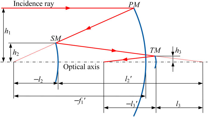
The coaxial TMA optical system structure is generally derived based on aberration theory. A schematic layout of the coaxial TMA optical system is shown in Figure 1. The system consists of three mirrors: primary mirror (PM), secondary mirror (SM), and tertiary mirror (TM). Assuming that the rays are incident from infinity and the aperture stop is located on the PM, the obscuration ratios of SM to PM and TM to SM are denoted as α1 and α2, respectively, the magnification ratios of SM and TM are represented as β1 and β2, respectively, and the conic coefficient of each mirror is e12, e22, and e32, respectively. The primary aberration coefficients can be expressed in terms of the profile coefficients, including obscuration ratios and magnification ratios. Due to the complexity of the specific expressions for the primary aberration coefficients, we will not go into details here. According to the primary aberration theory, the TMA optical system structural parameters can be calculated by the profile coefficients:
With the development of optical technology, optical freeform surfaces have gradually been applied, benefiting from their excellent aberration correction capabilities. As imaging performance improves, optical systems need to focus not only on the correction of the first three types of monochromatic aberrations but also on the importance of flat field design [26]. When the field curvature is zero, the condition for a flat image field can be obtained as follows:
By combining Equation 1 with Equation 2, the field flattening condition can also be written as:
According to Equation 3, in a TMA optical system, at least one mirror with negative optical power must be present to achieve the correction of field curvature. The coefficients that we can directly assign in the case of satisfying the field flattening condition are α1, α2, and β1, with β2 calculated from Equation 2.
2.2 Parameter analysis of TMA optical systems
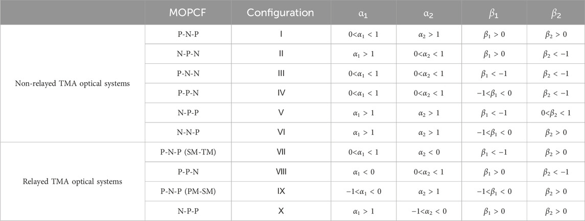
There are only two types of mirrors with optical powers: concave mirrors and convex mirrors, representing positive (P) and negative (N) optical powers, respectively. The TMA optical system has a total of eight mirror optical power combined forms (MOPCF). To achieve a flat field design, the MOPCF includes six types: “P-N-P”, “N-P-N”, “P-N-N”, “N-P-P”, “P-P-N”, and “N-N-P”. Among these, the combinations “P-N-P”, “P-P-N”, and “N-P-P” can produce an optical system with an intermediate image plane. The “P-N-P” combination, due to its symmetry, can result in the intermediate image plane being located between SM and TM (“P-N-P (SM-TM)”), or it can be located between PM and SM (“P-N-P (PM-SM)”). Therefore, the non-relayed TMA optical systems have six configurations, while the relayed optical systems have four configurations. Accordingly, there are a total of 10 configurations of TMA optical systems that can achieve a flat field design [27].
Based on the MOPCF in different configurations, the signs of the radius of curvature for each mirror are determined. The ranges for parameters α1, α2, β1, and β2 are calculated, as shown in Table 1. The ranges for these parameters presented in the table are necessary and insufficient conditions for obtaining the corresponding flat field off-axis TMA optical system. We have named the configurations corresponding to different MOPCFs and note that regardless of whether the TMA optical system is coaxial or off-axis, as long as it meets the same MOPCF, it can be said that the optical system belongs to the corresponding optical system configuration.
Based on the value range for the profile coefficients listed in Table 1, combined with Equation 1 and Equation 2, we can obtain the corresponding configuration of the off-axis TMA optical system through off-axis processing.
2.3 Grouping of TMA optical systems with different configurations
The 10 configurations of the TMA optical systems have both differences and similarities. Therefore, it is necessary to group these configurations for comparison. There are many criteria for grouping, which can be based on whether there is an intermediate image plane, as well as the combinations of optical power, size, image quality, and so on.
The tilt and decenter sensitivity are positively correlated with parameters such as the incidence angle and curvature, which are closely related to the dimensions of the optical system [14]. Therefore, in this paper, the grouping criterion adopted is the length of the optical system (mirror spacing, total length).
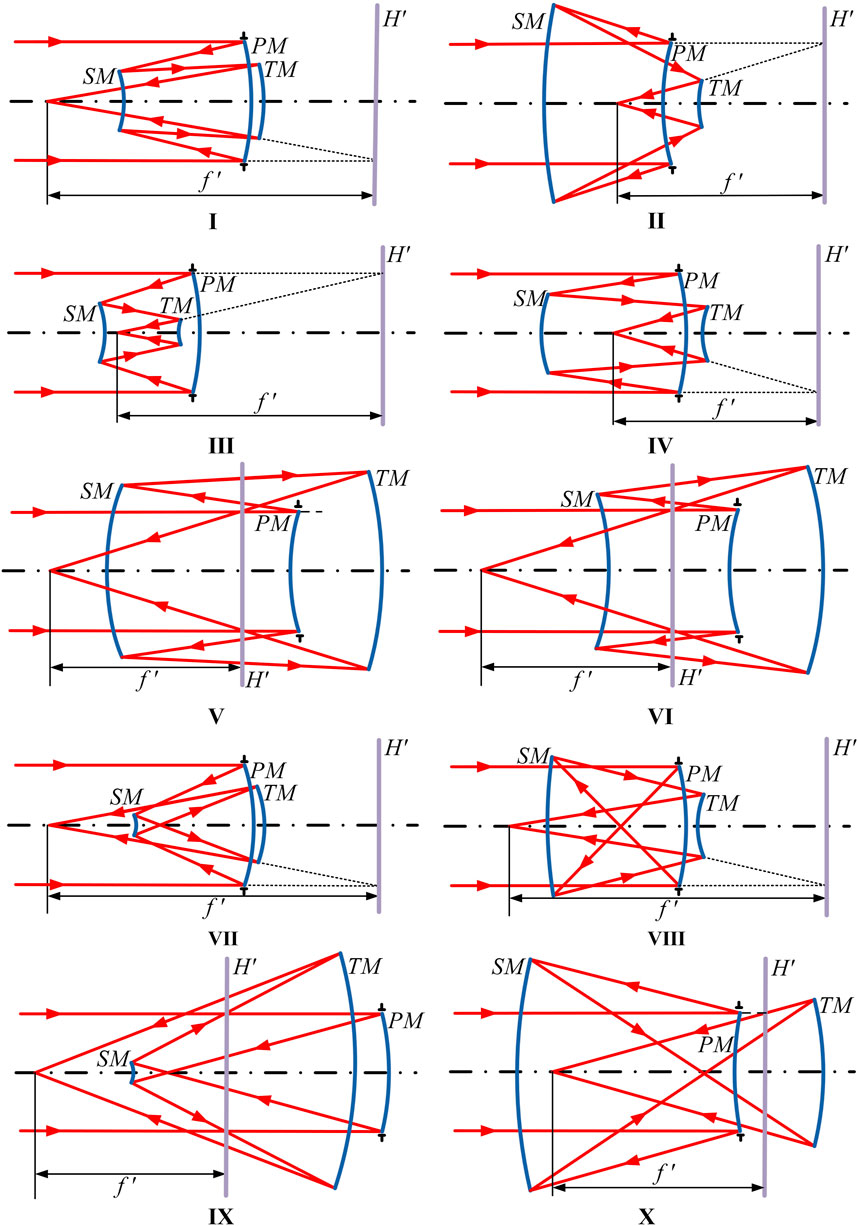
The off-axis TMA optical system has the same mirror spacing and total length as its coaxial TMA optical system before off-axis processing. Therefore, the different configurations of the coaxial TMA optical system established based on the parameters ranges in Table 1 are illustrated in Figure 2, with the PM set as the aperture stop, H′ representing the principal plane of the optical system, and the distance between the principal plane and the focal point is the focal length. The 10 configurations in Figure 2 are divided into two groups: configurations with a focal length greater than the total length (Group A) and configurations with a focal length less than the total length (Group B). The purpose of this grouping is merely to control variables, it does not imply Group A cannot be designed as an optical system with a focal length less than the total length, and the same for Group B.
The configuration in which the PM is concave, such as configurations I, III, IV, VII, and VIII, facilitates a relatively compact design. The total length of these systems is less than the focal length, which is similar to that of a telephoto objective structure. Although the PM in configuration II is convex, the MOPCF is “N-P-N”, which is relatively symmetrical, allowing it to be designed as Group A.
The MOPCF of configurations VII and IX are the same, the difference lies in the positions of the intermediate image plane. When the absolute value of α₁ is the same for both configurations, configuration IX needs several times larger TM than configuration VII for imaging. Therefore, configuration IX has a longer total length and also belongs to group B.
TMA optical systems in which the PM is convex enable a larger FOV, but they also result in a longer layout, similar to an reversed telephoto structure. Configurations II, V, VI, and X all belong to this category of optical systems.
The configurations contained in Group A and Group B are shown in Table 2, with six configurations in Group A, and four configurations in Group B. This grouping is also used for sensitivity comparison of off-axis TMA optical systems.
2.4 Low sensitivity freeform surface combination
Without significant changes in the layout of the optical system, the application of freeform surfaces can greatly improve the image quality of the optical system and further reduce the sensitivity. Freeform surfaces are generally obtained by superimposing freeform higher-order terms on a conic surface base. The expression for the freeform surface can be written as Equation 4:
where c refers to the vertex curvature, k is the conic coefficient, and Ai is the ith term coefficient of the freeform surface term, Qi (x, y) is used to describe the freeform surface polynomials. The low sensitivity freeform surfaces that we have used before are Fringe Zernike polynomial freeform surface (FZPF), Chebyshev polynomial freeform surface (CPF), and XY polynomial freeform surface. Using different combinations of these three types of surfaces on an off-axis TMA optical system, a low sensitivity freeform surface combination can be obtained through rational optimization analysis.
When using FZPF, CPF, and XYPF, we only use freeform surface polynomials of first to fourth order, and only the even terms of the freeform surface polynomial concerning X are used. The freeform surface terms for XYPF, CPF, and FZPF can be expressed separately as follows:
where am,n is the coefficient of XY polynomials in Equation 5, xmyn is the XY polynomials; am,n is the coefficient of Chebyshev polynomials in Equation 6, Cm,n (x, y) is the Chebyshev polynomials; and Ai is coefficient of Fringe Zernike polynomials in Equation 7, Zi (ρ, φ) is the ith Fringe Zernike polynomial.
2.5 Low sensitivity freeform off-axis TMA optical systems design method
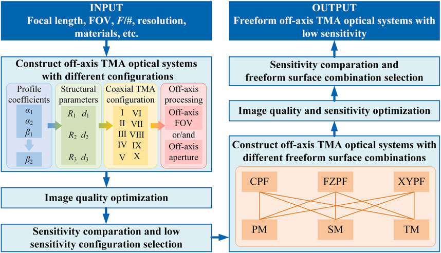
We propose a design method for low sensitivity freeform off-axis TMA optical systems based on the selection of initial structural configurations and freeform surface combinations, the schematic diagram of this method is shown in Figure 3.
1. Construct off-axis TMA optical systems with different configurations. Select the design specifications that can be achieved by the different configurations based on experience. Combined with Table 1 and 2, the coaxial TMA optical systems with different configurations in Group A and Group B can be designed. Through off-axis processing and image quality optimization, the off-axis TMA optical systems with different configurations are obtained.
2. Compare the sensitivity of the off-axis TMA optical systems with different configurations. Apply the same errors to all optical systems and compare the sensitivity of different configurations based on grouping. Select the optical systems with the lowest sensitivity from Group A and Group B. Compare the two optical systems, and redesign one of them to closely meet the length requirements of the other. Finally, the off-axis TMA optical system configuration with the lowest sensitivity is obtained.
3. Construct off-axis TMA optical systems with different freeform surface combinations. A low sensitivity off-axis TMA optical system configuration is obtained from step 2, and we design an initial structure based on this configuration to compare the effects of different freeform surface combinations. Apply the freeform surface combinations on three mirrors correctly to improve image quality and reduce sensitivity through optimization. Then, we obtain the off-axis TMA optical systems with different freeform surface combinations.
4. Sensitivity comparison and freeform surface combination selection. Apply the same errors to all optical systems and compare the sensitivity of different freeform surface combinations. Considering image quality and sensitivity comprehensively, the optimal combination of freeform surfaces that balances high image quality and low sensitivity is selected.
5. Design of freeform off-axis TMA optical system with low sensitivity. Based on the low sensitivity configuration, the off-axis TMA initial structure is obtained according to the specific design specifications and requirements. Combined with the low sensitivity freeform surface combination, a high-performance low sensitivity freeform off-axis TMA optical system is achieved through a reasonable optimization process.
3 Results
3.1 Design of off-axis TMA optical systems with different configurations
The off-axis TMA optical system is derived from the coaxial TMA optical system by eliminating obscuration. In some optical systems, obscuration can be eliminated by a mere off-axis FOV, in which case the aperture stop is typically set at the SM. In some optical systems, obscuration can be eliminated simply by an off-axis aperture, where the aperture stop is usually placed at the PM. Furthermore, some other optical systems use a single off-axis approach that does not eliminate obscuration, necessitating a combination of methods. In this paper, when designing off-axis TMA optical systems of different configurations, we eliminate obscuration according to the characteristics of different structures. To minimize the variables in the comparison process, we set the aperture stop to the PM for all systems.
To ensure that all configurations of the off-axis TMA optical system have good image quality, we choose the design specifications for the optical systems to have a focal length of 100 mm, an F-number of 10, an FOV of 1° × 1°, and an image quality characterized by RMS WFE of less than 0.04λ (λ = 632.8 nm).
By assigning values to the profile coefficients, we can design numerous optical systems with the same configuration and specifications but different dimensions. We try to unify the total lengths of the optical systems. Based on experience, the total lengths of the optical systems in Group A are set to 44 cm × (1 ± 5%), while the total lengths of the optical systems in Group B are set to 180 cm × (1 ± 5%). The naming rule of the optical systems is “Group-Configuration”.
The layout of the off-axis TMA optical systems for Group A is shown in Figure 4, and the layout of the off-axis TMA optical systems for Group B is shown in Figure 5. All the optical systems are non-obscuration, with MTF close to the diffraction limit and RMS WFE less than 0.04λ, and the lengths of the optical systems in the same group have no significant differences, meeting the design specifications.
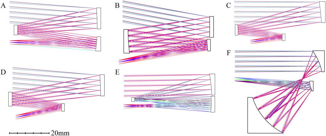
Figure 4. Optical system layout of Group A (A) “System A-I”; (B) “System A-II”; (C) “System A-III”; (D) “System A-IV”; (E) “System A-VII”; (F) “System A-VIII”.
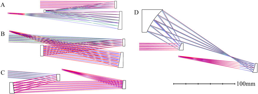
Figure 5. Optical system layout of Group B (A) “System B-V”; (B) “System B-VI”; (C) “System B-IX”; (D) “System B-X”.
3.2 Sensitivity analysis of off-axis TMA optical systems with different configurations
Sensitivity analysis was performed for the off-axis TMA optical systems with different configurations. Decenter (tangential: ±0.2 mm, sagittal: ±0.2 mm) and tilt (tangential: ±0.2°, sagittal: ±0.2°) are simultaneously applied to the systems. The results of 2000 Monte Carlo analyses were used to statistically analyze the sensitivity of the optical systems. Sensitivity was represented by the amount of change in image quality before and after the errors were generated, denoted as ΔRMS WFE. We present the image quality and sensitivity comparison of the off-axis TMA optical systems from Group A and Group B in Table 3.
The optical system with the lowest sensitivity in Group A is “System A-I”. “System A-I” and “System A-VII” represent the two commonly used optical systems. The lengths of the two systems are identical, but the optical power of “System A-VII” differs from that of “System A-I” by nearly a factor of two. Therefore, the sensitivity of “System A-VII” is 3.4 times that of “System A-I”. We analyze the decenter and tilt sensitivity of “System A-I” and “System A-VII” separately. The decenter sensitivity of “System A-I” is 0.0072λ, while that of “System A-VII” is 0.0484λ. The decenter sensitivity of “System A-VII” is 6.7 times that of “System A-I.” The tilt sensitivity of “System A-I” is 0.0126λ, and that of “System A-VII” is 0.0232λ. The tilt sensitivity of “System A-VII” is 1.8 times that of “System A-I”.
The optical system with the lowest sensitivity in Group B is “System B-VI”. The sensitivity of “System B-IX” is also at a relatively low level; however, “System A-VII”, with a total length more than four times smaller than that of “System B-IX”, has a sensitivity that is only about four times that of “System B-IX”. Additionally, the aberration correction capability of configuration IX is poorer, making it unable to achieve a design as compact as that of configuration VII. It also lacks advantages in achieving higher performance compared to configuration VII.
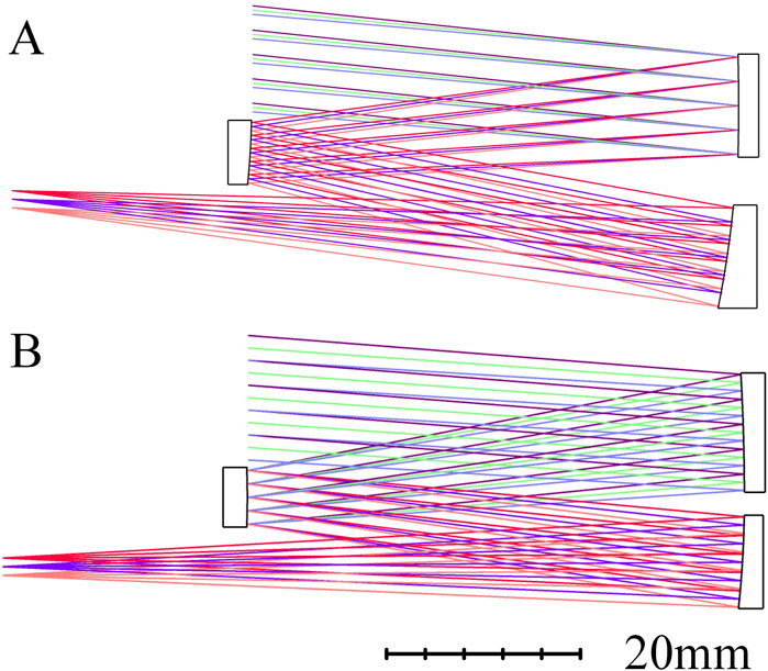
Generally, the smaller the optical power of each mirror in a conic TMA optical system, the lower the sensitivity within a reasonable range [28, 29]. Therefore, we have redesigned an off-axis TMA optical system that conforms to configuration I. The length is more closely aligned with “System B-VI”, named “System A-I1”, as shown in Figure 6A. This optical system has a total length of 75 cm, and the RMS WFE of “System A-I1” is 0.0318λ, which yields a sensitivity of 0.0073λ under the same error perturbation conditions. Setting the aperture stop of “System A-I1” as the SM results in “System A-I2”, as shown in Figure 6B, where the RMS WFE of “System A-I2” is 0.0305λ, and the sensitivity is 0.0091λ. Thus, regardless of whether the aperture stop of the off-axis TMA optical system corresponding to the configuration I is at SM or PM, when the total length is 75 cm, it exhibits a sensitivity lower than all optical systems in “Group B” by more than double. As shown in Figures 4, 5 and Table 3, we can conclude that configuration I is the one with the lowest sensitivity among all configurations of the same size.
In the configuration I, the MOPCF of “P-N-P” with different optical power value distributions can produce various geometric layouts. The geometric layouts of the optical systems we designed that conform to the configuration I (“System A-I”, “System A-I1”, “System A-I2”) have the greatest potential for aberration correction after applying freeform surfaces [30]. Therefore, we use “System A-I2” as the initial structure, as shown in Figure 6B, to complete the design of various types of low sensitivity freeform off-axis TMA optical systems.
3.3 Design of low sensitivity freeform off-axis TMA optical systems
“System A-I2” has great potential for aberration correction after the application of freeform surfaces combination with low sensitivity. In this section, we take “System A-I2” as the starting point and introduce freeform surfaces into the optical system to further improve image quality and reduce sensitivity. ΔRMS WFE is still used to evaluate the sensitivity in this section.
Our team previously used different combinations of these three freeform surface types (FZPF, XYPF, and CPF) on the same off-axis TMA optical system’s initial structure [25]. The initial structure used in previous research possesses the same configuration as “System A-I2”. Research revealed that different combinations of freeform surfaces have varying effects on image quality and sensitivity. Regardless of the combination of freeform surfaces used, all combinations can achieve the goal of improving image quality and reducing sensitivity. When the PM, SM, and TM are CPF, FZPF, and XYPF (which we call the “C-FZ-XY” combination), respectively, the optical system reaches optimal image quality and sensitivity. Therefore, in this paper, steps 3 and 4 are not performed to screen out the freeform surface combination that can achieve the best balance between image quality and sensitivity, and the conclusions of the previous study are directly followed, the “C-FZ-XY” combination is chosen for the subsequent design of a freeform off-axis TMA optical system with low sensitivity.
We have designed freeform off-axis TMA optical systems with low sensitivity and features such as fast F-number, large FOV, and long focal length, respectively. Of course, many other types of optical system designs can demonstrate the capabilities of freeform surfaces. Due to space limitations, we will not enumerate them all, but will only showcase a few of the most typical low sensitivity freeform TMA optical system designs.
3.3.1 Low sensitivity freeform off-axis TMA optical system with a fast F-number
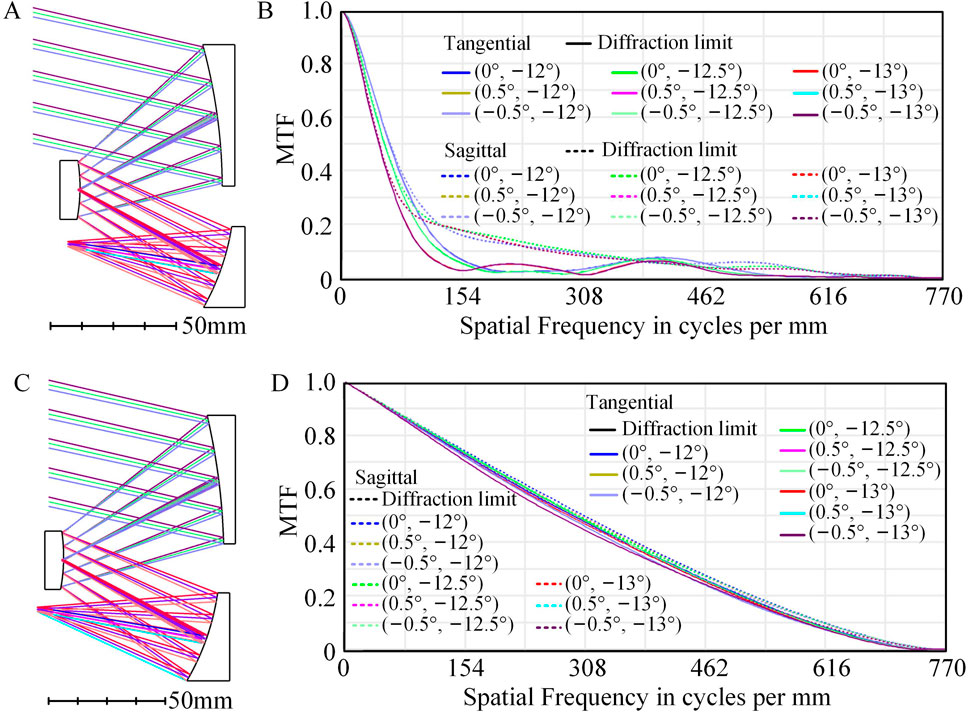
The entrance pupil diameter of “System A-I2” is enlarged by 5 times, and a low sensitivity fast F-number off-axis TMA optical system with a focal length of 100 mm, an FOV of 1 ° × 1 ° (tangential: −12° ∼ −13°, sagittal: −0.5° ∼ 0.5°), and an F-number of 2 is designed, named “System 1”. All three mirrors of “System 1” are conic surfaces with fewer DOFs. Layout and MTF of “System 1” are shown in Figures 7A, B, with an RMS WFE of 0.357λ, indicating that the optical system has poor image quality.
The optical system optimized using the “C-Z-XY” freeform surface combination is named “System 2”. Layout and MTF of “System 2” are shown in Figures 7C, D. After applying the freeform surfaces, the MTF of “System 2” approaches the diffraction limit, and the average RMS WFE of “System 2” is 0.0285λ, indicating good image quality.
The F-number of “System 2” is 2, while the F-number of “System A-I2” is 10, resulting in a difference of 5 times between the two F-numbers, making it impossible to compare their sensitivities directly. However, “System A-I2” serves as the initial structure for “System 2”, with a total length of 75 mm, while “System 2” has a total length of 78 mm, and the structural layout has not changed significantly. Tilt (tangential: ±10″, sagittal: ±10″) and decenter (tangential: ±10μm, sagittal: ±10 μm) are applied to all optical surfaces of “System 2”. The sensitivity of “System 2” is analyzed by using a 2000 Monte Carlo tolerance analysis, and the results are shown in Figure 8A, where the RMS WFE degrades to an average of 0.0441λ under the influence of errors, and the sensitivity is 0.0156λ. The RMS WFE and ΔRMS WFE for the full FOV of “System 2” are compared in Figure 8B, indicating that the distribution of image quality and sensitivity is relatively uniform, with good image quality and low sensitivity. “System 2” thus represents a fast F-number freeform off-axis TMA optical system with low sensitivity.
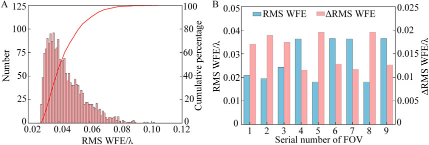
Figure 8. (A) Monte Carlo tolerance analysis results of “system 2”; (B) RMS WFE and ΔRMS WFE comparison of full FOV.
3.3.2 Low sensitivity freeform off-axis TMA optical system with a large rectangular FOV
The entrance pupil diameter of “System A-I2” is enlarged by 2 times, and the FOV in the tangential and sagittal directions is magnified by 10 times, separately. A low sensitivity large rectangular FOV off-axis TMA optical system with a focal length of 100 mm, an FOV of 10 ° × 10 ° (tangential: −6° ∼ −16°, sagittal: −5° ∼ 5°), and an F-number of 5 is designed. When freeform surfaces are not used, the optical system optimized for image quality is named “System 3”. Layout and MTF of “System 3” are shown in Figures 9A, B, with an RMS WFE of 0.104λ, indicating that the image quality of the system is relatively poor.
The optical system obtained after using the “C-Z-XY” combination is named “System 4”. Layout and MTF of “System 4” are shown in Figures 9C, D. After employing freeform surfaces, the MTF of the “System 4” approaches the diffraction limit, and the average RMS WFE of “System 4” is 0.0366λ, indicating good image quality.
Similarly, the total length of “System 4” is 80 mm, and the structural layout does not significantly change compared to “System A-I2”. Tilt (tangential: ±2′, sagittal: ±2′) and decenter (tangential: ±20μm, sagittal: ±20 μm) are applied to all optical surfaces of “System 4”, and 2000 Monte Carlo tolerance analyses are performed to assess the sensitivity of “System 4”. The results of the Monte Carlo analysis for “System 4” are shown in Figure 10A, which reveals that the RMS WFE degrades to 0.0496λ under error influence, with a sensitivity of 0.0130λ. The comparison of the RMS WFE and ΔRMS WFE for “System 4” across the full FOV is shown in Figure 10B. The sensitivity of the optical system is at a relatively low level, indicating that “System 4” is the freeform off-axis TMA optical system with a large rectangular FOV that possesses low sensitivity.
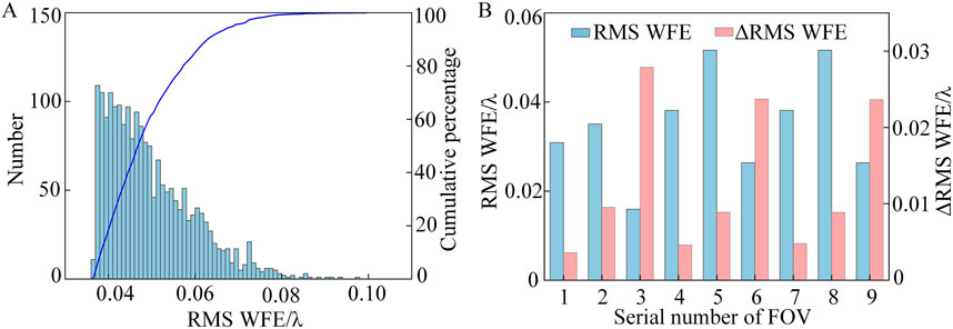
Figure 10. (A) Monte Carlo tolerance analysis results of “System 4”; (B) RMS WFE and ΔRMS WFE comparison of full FOV.
3.3.3 Low sensitivity freeform off-axis TMA optical system with a long focal length
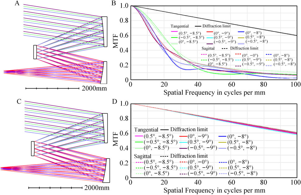
The entrance pupil diameter of “System A-I2” is enlarged by a factor of 2, and the focal length is increased by a factor of 20 to design a low sensitivity long focal length TMA optical system with a focal length of 5,000 mm, a rectangular FOV of 1 ° × 1 ° (tangential: −8° ∼ −9°, sagittal: −0.5° ∼ 0.5°), and an F-number of 5. When freeform surfaces are not used, all three mirrors of the optical system are conic surfaces, and the optimized optical system is named “System 5”. Layout and MTF of “System 5” are shown in Figures 11A, B, with an RMS WFE of 0.555λ, indicating that the image quality is relatively poor.
The optical system optimized using the “C-Z-XY” combination is named “System 6”. Layout and MTF of “System 6” are shown in Figures 11C, D. After employing freeform surfaces, the MTF of the “System 6” approaches the diffraction limit, and the average RMS WFE of “System 6” is 0.0179λ, indicating good image quality.
In the same way, the MOPCF and optical power value distribution of “System 6” shows no significant difference from “System A-I2”. Tilt (tangential: ±3″, sagittal: ±3″) and decenter (tangential: ±50μm, sagittal: ±50 μm) are applied to all optical surfaces of “System 6”, and 2000 Monte Carlo tolerance analyses are performed to assess the sensitivity of “System 6”. The results of the Monte Carlo analysis for “System 6” are shown in Figure 12A, where the average RMS WFE degrades to 0.0459λ under the influence of errors, with a sensitivity of 0.0280λ. The comparison of the RMS WFE and ΔRMS WFE across the full FOV for “System 6” is presented in Figure 12B, indicating that the image quality and sensitivity of the optical system are uniformly distributed across all FOVs. The sensitivity in this volume of optical systems is at a low level, making “System 6” a long focal length freeform off-axis TMA optical system with low sensitivity.

Figure 12. (A) Monte Carlo tolerance analysis results of “System 6”; (B) RMS WFE and ΔRMS WFE comparison of full FOV.
4 Discussion
4.1 Discussion of the low sensitivity configurations of the off-axis TMA optical systems
The sensitivity to misalignment errors in relayed TMA optical systems is significantly higher than that of non-relayed TMA optical systems according to Figures 4, 5 and Table 3. In the relayed TMA optical systems, configuration VII has good image quality and relatively low sensitivity, as shown in Figure 4E. The aperture stop of this system is placed on the PM, with a relatively large FOV of 1.5°–3°, a compact structure, and it generally achieves a telephoto ratio of 6. In the non-relayed TMA optical systems, configuration I and VI have good image quality and relatively low sensitivity, as shown in Figures 4A, 5B. The advantage of configuration I is that the aperture stop is generally placed on the SM, and the PM and TM are relatively symmetrical, allowing for the design of large FOV optical systems, with an FOV of 3°–20°. Additionally, this system can be designed as an image telecentric system, resulting in low distortion, making it suitable for surveying cameras. When we pursue a large rectangular FOV, configuration VI is a good choice with low sensitivity and the ability to achieve a large rectangular FOV. When the aperture stop is set between the SM and TM, this configuration is known as the Hughes Walrus optical system, this configuration is quite large in volume [26].
In this paper, sensitivity is considered the most important index to select the configuration I to design the low sensitivity optical system. However, in the actual application process, we need to select the configuration according to the specific design index.
4.2 Discussion of freeform surface combinations and design results
The configuration we applied in our previous research is the same as the configuration of the optical system with the lowest sensitivity obtained in this paper [25], the image quality and sensitivity are improved simultaneously by applying freeform surfaces correctly. When the PM adopts CPF, the SM adopts ZFPF, and the TM adopts XYPF, the freeform off-axis TMA optical system achieve its optimal as-built performance. Although in different optical systems, the effects that different freeform surfaces can achieve vary significantly, regardless of the optical system’s geometric form, the freeform surface combination “C-FZ-XY” is quite useful for this configuration.
By combining the off-axis TMA optical system configuration and the freeform surface combination, both of which have the lowest sensitivity, freeform off-axis TMA optical systems with low sensitivity are designed. In the design process, starting from the low sensitivity initial structure configuration selection to the subsequent screening of low sensitivity freeform surface combination for optimization, both effectively avoid those design directions that deviate from low sensitivity, and the off-axis TMA optical systems with low sensitivity are designed directly. Since the application of freeform surfaces enables the realization of high-performance optical systems, in this paper, low sensitivity freeform off-axis TMA optical systems with fast F-number, large FOV, and long focal length are designed using “System A-I2” shown in Figure 6B as the initial structure. Of course, designers can also design other types of freeform optical systems with low sensitivity using the method we proposed.
5 Conclusion
The low sensitivity freeform off-axis TMA optical system can achieve high imaging performance and has a strong ability to resist error disruption. In this paper, the sensitivity of different configurations of the off-axis TMA optical systems is compared, and the configuration with the lowest sensitivity is obtained. Based on the initial structure conforming to the low sensitivity configuration, incorporating a freeform surface combination that can further reduce the sensitivity and improve optical system performance, several freeform off-axis TMA optical systems with low sensitivity are designed, which can achieve a fast F-number, a large rectangular FOV, and a long focal length separately.
Data availability statement
The original contributions presented in the study are included in the article/supplementary material, further inquiries can be directed to the corresponding author.
Author contributions
CR: Conceptualization, Data curation, Formal Analysis, Investigation, Methodology, Software, Validation, Visualization, Writing–original draft, Writing–review and editing. QM: Conceptualization, Funding acquisition, Methodology, Project administration, Resources, Supervision, Writing–review and editing. QC: Software, Writing–review and editing.
Funding
The author(s) declare that financial support was received for the research, authorship, and/or publication of this article. This research was funded by the National Natural Science Foundation of China (62375264, 62235018); and the Youth Innovation Promotion Association of the Chinese Academy of Sciences (Y2023061).
Conflict of interest
The authors declare that the research was conducted in the absence of any commercial or financial relationships that could be construed as a potential conflict of interest.
Publisher’s note
All claims expressed in this article are solely those of the authors and do not necessarily represent those of their affiliated organizations, or those of the publisher, the editors and the reviewers. Any product that may be evaluated in this article, or claim that may be made by its manufacturer, is not guaranteed or endorsed by the publisher.
References
1. Figoski JW. Alignment and test results of the QuickBird telescope using the ball optical system test facility. Proc SPIE (1999) 3785:99–108. doi:10.1117/12.367607
2. Clampin M. Status of the James Webb space telescope observatory. Proc SPIE (2012) 8442:84422A. doi:10.1117/12.926429
3. Leisawitz D, Amatucci E, Carter R, DiPirro M, Flores A, Staguhn J, et al. The origins space telescope: mission concept overview. Proc SPIE (2018) 10698:40. doi:10.1117/12.2313823
4. Meng QY, Wang D, Wang XD, Li W, Yang XW, Yan DJ, et al. High resolution imaging camera (HiRIC) on China’s first Mars exploration Tianwen-1 mission. Space Sci Rev (2021) 217:42–29. doi:10.1007/s11214-021-00823-w
5. Zhao HX, Gao LM, Mao XL, Duan YX, Xue X. Design method of freeform off-axis three-mirror reflective imaging systems. Appl Opt (2023) 62(29):7852–9. doi:10.1364/AO.498270
6. Deng YT, Tan YL, Wu XF, Zhu J. Local tolerance and quality evaluation for optical surfaces. Optica (2022) 9(9):1039–49. doi:10.1364/OPTICA.459633
7. Thompson KP, Jannick PR. Freeform optical surfaces: a revolution in imaging optical design. Opt Photon News (2012) 23(6):30–5. doi:10.1364/OPN.23.6.000030
8. Rolland JP, Davies MA, Suleski TJ, Evans C, Bauer A, Lambropoulos JC, et al. Freeform optics for imaging. Optica (2021) 8(2):161–76. doi:10.1364/OPTICA.413762
9. Reimers J, Bauer A, Thompson KP, Rolland JP. Freeform spectrometer enabling increased compactness. Light Sci Appl (2017) 6(7):e17026. doi:10.1038/lsa.2017.26
10. Tan YL, Zhu J. Freeform surfaces that enable high-quality Offner-type imaging spectrometers with holographic grating. Opt Express (2023) 31(26):43269–79. doi:10.1364/OE.511663
11. Ren CM, Meng QY. Design method for freeform off-Axis three-mirror anastigmat optical systems with a large field of view and low error sensitivity. Photonics (2024) 11(3):211. doi:10.3390/photonics11030211
12. Zhong Y, Gross H, Broemel A, Kirschstein S, Petruck P, Tuennermann A. Investigation of TMA systems with different freeform surfaces. Proc SPIE (2015) 9626:229–38. doi:10.1117/12.2191228
13. Zhao GX, Zhu J. Design method of off-axis reflective freeform zoom optical systems. Opt Express (2024) 32(16):28806–20. doi:10.1364/OE.530798
14. Qin ZC, Wang XD, Ren CM, Qi YS, Meng QY. Design method for a reflective optical system with low tilt error sensitivity. Opt Express (2021) 29(26):43464–79. doi:10.1364/OE.447556
15. Gu ZY, Wang Y, Yan CX. Optical system optimization method for as-built performance based on nodal aberration theory. Opt Express (2020) 28(6):7928–42. doi:10.1364/OE.383727
16. Thompson KP, Schiesser E, Rolland JP. Why are freeform telescopes less alignment sensitive than a traditional unobscured TMA? Proc SPIE (2015) 9633:963317. doi:10.1117/12.2195784
17. Ren CM, Meng QY. Reflecting optical systems desensitization: modulation by freeform surfaces. Opt Lasers Eng (2024) 180:108317. doi:10.1016/j.optlaseng.2024.108317
18. Zhang BQ, Jin GF, Zhu J. Towards automatic freeform optics design: coarse and fine search of the three-mirror solution space. Light Sci Appl (2021) 10(1):65. doi:10.1038/s41377-021-00510-z
19. Wassermann GD, Wolf E. On the theory of aplanatic aspheric systems. Proc Phys Soc London, Sect B (1949) 62(1):2–8. doi:10.1088/0370-1301/62/1/302
20. Miñano JC, Benítez P, Lin W, Infante J, Muñoz F, Santamaría A. An application of the SMS method for imaging designs. Opt Express (2009) 17(26):24036–44. doi:10.1364/OE.17.024036
21. Lin W, Benítez P, Miñano JC, Infante J, Biot G. Advances in the SMS design method for imaging optics. Proc SPIE (2011) 8167:81670M. doi:10.1117/12.897293
22. Duerr F, Benítez P, Miñano JC, Meuret Y, Thienpont H. Analytic design method for optimal imaging: coupling three ray sets using two freeform lens profiles. Opt Express (2012) 20(5):5576–85. doi:10.1364/OE.20.005576
23. Yang T, Zhu J, Wu XF, Jin GF. Direct design of freeform surfaces and freeform imaging systems with a point-by-point three-dimensional construction-iteration method. Opt Express (2015) 23(8):10233–46. doi:10.1364/OE.23.010233
24. Pan HX, Su ZP, Zhang YL, Wu T. Construct freeform surface directly in an initial layout of an off-axis reflective image system by seed curve extension and simulated annealing algorithm. J Eur Opt Soc-rapid (2020) 16:9. doi:10.1186/s41476-020-00130-x
25. Qin ZC, Qi YS, Ren CM, Wang XD, Meng QY. Desensitization design method for freeform TMA optical systems based on initial structure screening. Photonics (2022) 9(8):544. doi:10.3390/photonics9080544
26. Meng QY. Overview of three-mirror reflective optical system. Infrared Laser Eng (2022) 51(1):20210986–1. doi:10.3788/IRLA20210986
28. Qin ZC, Meng QY, Wang XD. Desensitization design method of a freeform optical system based on local curve control. Opt Lett (2022) 48(1):179–82. doi:10.1364/OL.480641
29. Liu XY, Gong TT, Jin GF, Zhu J. Design method for assembly-insensitive freeform reflective optical systems. Opt Express (2018) 26(21):27798–811. doi:10.1364/OE.26.027798
Keywords: optical design, freeform surface, off-axis TMA optical systems, low sensitivity, configuration selection
Citation: Ren C, Meng Q and Chen Q (2024) Desensitization design of freeform off-axis TMA optical systems with configuration selection. Front. Phys. 12:1486924. doi: 10.3389/fphy.2024.1486924
Received: 27 August 2024; Accepted: 18 October 2024;
Published: 30 October 2024.
Edited by:
Tong Yang, Beijing Institute of Technology, ChinaReviewed by:
Yue Liu, Xi’an Jiaotong University, ChinaJingfei Ye, Nanjing University of Information Science and Technology, China
Copyright © 2024 Ren, Meng and Chen. This is an open-access article distributed under the terms of the Creative Commons Attribution License (CC BY). The use, distribution or reproduction in other forums is permitted, provided the original author(s) and the copyright owner(s) are credited and that the original publication in this journal is cited, in accordance with accepted academic practice. No use, distribution or reproduction is permitted which does not comply with these terms.
*Correspondence: Qingyu Meng, bWVuZ3F5QGNpb21wLmFjLmNu
 Chengming Ren
 Qingyu Meng1*