- 1School of Physics, Xidian University, Xi’an, China
- 2Engineering Research Center of Information Nanomaterials, Universities of Shaanxi Province, Xi’an, China
- 3Xi’an Engineering Research Center of Super-Resolution Optical Microscopy, Xi’an, China
- 4School of Electronic and Optical Engineering, Nanjing University of Science and Technology, Nanjing, China
In this work, we propose a structured-illumination lensless digital holographic microscopy (SI-LDHM). SI-LDHM illuminates a sample with 24 structured illuminations (8 orientations × 3 phase shifts) and records the defocused interferogram formed by two copies of object waves along the ±1st diffraction orders of each SI. The reconstructed object waves under different illumination orientations are respectively propagated to the sample plane along the +1st diffraction order and then averaged, thus yielding a clean image without the artifact of twin images. Experimental results demonstrated that thanks to the multi-oriented SI strategy, the twin image in SI-LDHM is sevenfold reduced compared to conventional DHM, while the spatial resolution is 1.15 times higher.
1 Introduction
Digital holographic microscopy (DHM), which combines interferometry with optical microscopy and utilizes a digital camera to record the generated hologram, has been acting as one of the most accurate quantitative phase microscopy techniques [1–3]. Different with conventional optical microscopy that renders the contrast of samples utilizing the absorption/reflection of light by the sample or fluorescence excitation/emission regime, DHM is capable of recovering intrinsic contrast for transparent or translucent samples by exploring the phase of the imaging light field. Meanwhile, DHM features another merit, i.e., autofocusing, with which an in-focused image can be obtained by digitally propagating an object wave from the hologram plane to the image plane [4]. So far, DHM has been widely applied to various fields, including industrial inspection [5, 6], biomedical study [7–11], and so on.
Often DHM employs independent object and reference waves that are separate in space, and hence it is susceptible to environmental disturbances. To alleviate this dilemma, researchers resort to vibration isolation [12], degenerative feedback [13], or common-path configurations [14–18]. Among common-path DHM configurations, point-diffraction DHM [15–17] utilizes a grating to split an object wave under investigation into two copies, one of which is filtered with a pinhole into a plane wave acting as the reference wave, and the other is retained as the object wave. This technique preserves the concept of DHM (coding the phase into interference patterns) and its simple reconstruction regime. Yet, the contrast and consequently the signal-to-noise ratio (SNR), is sample-dependent since the reference wave is generated by pinhole fielding of the object wave spectrum. As a remedy, a polarization-grating-based point-diffraction DHM (PG-DPM) utilizing a polarization diffraction grating for beam splitting was proposed, where the fringe contrast can be adjusted by manipulating the polarization of the illumination light [18]. To further upgrade, structured illumination was incorporated into point-diffraction DHM for both resolution enhancement [4] and 3D RI imaging [19, 20].
Another important issue in DHM is spatial bandwidth product (SBP). Often, DHM employs a microscopic lens to magnify the image of a sample. Yet, it often posts a limit on the imaging SBP, for instance, a 20×/0.4 objective usually provides a spatial resolution δ = 0.61 λ/NA = 965 nm within a field of view (FOV) of 1 × 1 mm2, yielding a valid SBP of 1.07 M pixels. Such SBP is around 1/10 sampling power of the state-of-the-art cameras. For example, an sCMOS camera [Basler boA6500-36cm, Basler Vision Technology (Beijing) Co., Ltd., China] has 6560 × 4948 pixels (32.5 M), which is tenfold higher than lens-based DHM. Recently, Samsung electronics company recently developed a CMOS image sensor with 200 M pixels and a pixel size of 0.56 μm [21]. To realize large-field DHM imaging, lens-based DHM resorts to mechanical translating a sample multiple times, capturing interferograms for each objective-FOV-covered region on the specimen, and digitally stitching the reconstructed image together. To alleviate this laborious process, on-chip quantitative phase microscopy approaches based on illumination scanning [22], wavelength scanning [23], and relative displacement between the sample and the image sensor [24, 25] were reported to achieve quantitative phase imaging with ultra-large spatial bandwidth product (SBP) and pixel super-resolution.
Inspired by on-chip DHM, in this work, we present and demonstrate a structured illumination lensless digital holographic microscopy (abbreviated as SI-LDHM). SI-LDHM utilizes structured illumination (SI) to generate the interference of two copies of the object waves along the ±1st diffraction orders of SIs, and suppresses the twin image by averaging the reconstructed object waves along different SIs. Compared to conventional LDHM, SI-LDHM is immune to environmental disturbances, and has a reduced speckle noise level and enhanced spatial resolution, benefiting from the SIs.
2 Methods
2.1 Experimental setup of SI-LDHM
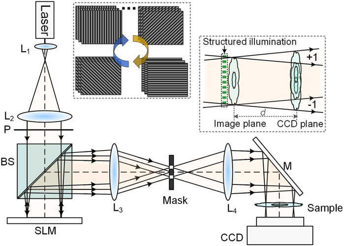
The schematic diagram of the SI-LDHM system is shown in Figure 1. A 633-nm He-Ne laser is used as the illumination source. The laser output is expanded by a telescope system L1-L2, and guided to a phase-type spatial light modulator (SLM, 1920 × 1080 pixels, pixel size 7.56 μm, DLP F6500, UPO Labs Co., Ltd., China) after passing through a cube beam splitter BS. A linear polarizer P with its transmission polarization orientation along the horizontal direction is located before the BS to optimize the modulation efficiency of the SLM. Eight groups of binary fringe patterns (featuring a period of six pixels and binary phases 0/π) with a grating vector azimuth θm = mπ/8 are loaded to the SLM sequentially, m = 1, 2 … 8. The fringe patterns are shifted three times for each orientation, yielding a phase shift of 2π(n−1)/3 with n = 1, 2, 3. Then, the patterns displayed on SLM are projected via a telescope system L3-L4 to a sample, which is located with a distance d = 27 mm above a CMOS camera (4,000

Figure 1. Schematic diagram of SI-LDHM. BS, beamsplitter; CCD, charge-coupled device; L1-L4, achromatic lens; M, Mirror; P, polarizer; SLM, spatial light modulator. The upper-left inset shows four phase gratings loaded to SLM sequentially, and the lower-right inset shows the schematics of interferogram forming with structured illumination.
2.2 Numerical reconstruction of SI-LDHM
In this section, we briefly elaborate the reconstruction algorithm of SI-LDHM. The structured illumination on the sample plane can be written as Equation 1:
where A0 denotes the amplitude magnitude of the structured illumination.
Actually, the interferogram Im,n is an off-axis interferogram, and the carrier frequency 1/14.8 μm−1 is induced by the angle (that is 2.45o) between the ±1st diffraction orders of the SI. Using the reconstruction algorithm of three-step phase shifting interferometry (PSI), the complex amplitude of the real image Om,1Om,-1* of the Im,n can be obtained with Equation 3:
As shown in Figure 3A, Om,1Om,-1* contains two copies of object waves Om,1 and Om,-1*, which have the opposite defocusing distances +d and −d, respectively. Digital refocusing of Om,1 is performed by propagating Om,1Om,-1* for a distance of d, using Equation 4:
where FT[·] and IFT[·] represent the Fourier transform and inverse Fourier transform operators, respectively. The term exp(−i
After the averaging operation in Equation 5, the contrast of the twine image is reduced by a factor of eight. We also find that the defocusing of 2d acts as another key factor in reducing the contrast of the twine image Om,-1*. Meanwhile, the spatial resolution of the reconstructed
3 Experimental results
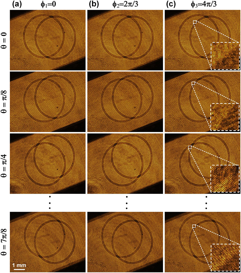
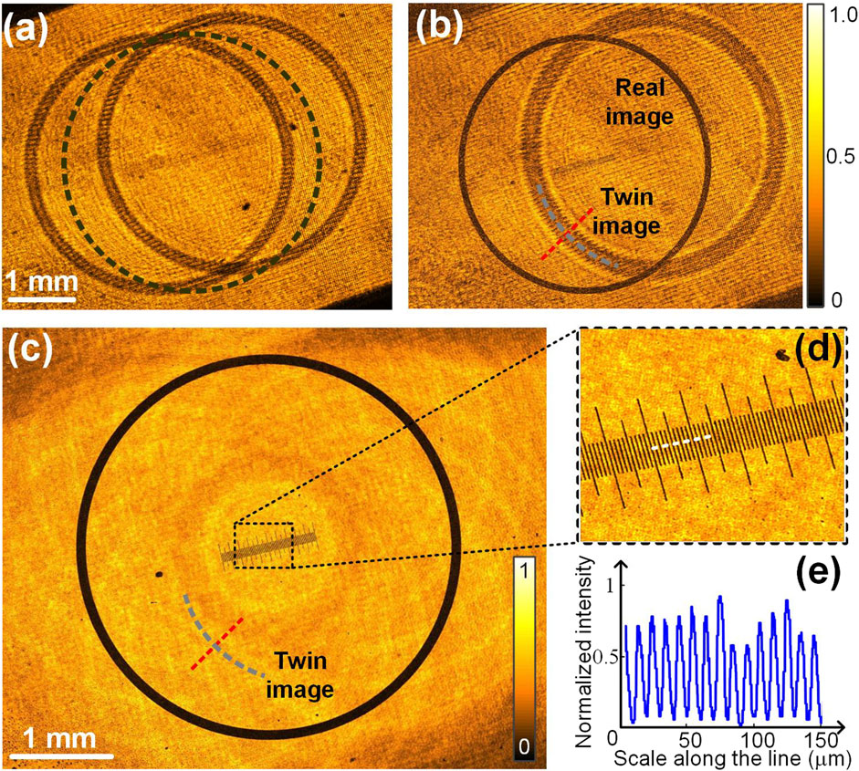
A micro-ruler surrounded by a ring etched on a glass plate was used as the sample to test the feasibility of SI-LDHM. 8 (orientation)×3 (phase-shifting) fringe patterns with a period of six pixels were loaded sequentially to the SLM, and the CMOS camera recorded interferograms when the sample is illuminated by each SIs. Figures 2A–C show the interferograms recorded under the SIs of 8 orientations (along the Y direction) and 3 phase shifts (along the X direction). It can be seen that under each SI, there are two copies of object images, which are rotated with the SI orientation. The inset in Figure 2C shows the fringe patterns in the interferogram, featuring a period of 22.6 μm, sampled by 12 pixels. The complex amplitude of Om,1Om,-1* was reconstructed using Equation 3, and Figure 3A illustrates the reconstructed amplitude image of the sample. The defocus distances of the images Om,1 and Om,-1* from the sample plane are 27 mm and −27 mm, respectively, resulting in similar intensity distributions. Once Om,1Om,-1* was digitally propagated for a defocusing distance of −27 mm to the sample plane along the +1st diffraction order of the SI using Equation 4, the real image of Om,1 became focused, while the twin image Om,-1* became increasingly defocused by 54 mm, shown in Figure 3B. After the 8 refocused images of Om,1Om,-1* along different SIs were averaged, the obtained amplitude of the sample is shown in Figure 3C. It can be seen that both the micro-rule and the ring have sharp structures, and the artifacts of twin images are well suppressed. The contrast of the twin image was evaluated quantitatively by analyzing the intensity modulations along the short lines in (b) and (c) with V=(Imax - Imin)/(Imax + Imin). Here, Imax and Imin are the maximal and minimal intensity of the line. The analysis turns out that V = 0.43 for a single structured illumination and V = 0.06 after averaging the reconstructions under eight groups of structured illuminations, implying a sevenfold reduction of the twin image contrast. Despite eight groups of SIs being demonstrated in this study, fewer illumination numbers can be used to enhance the imaging speed of SI-LDHM. While four illumination orientations are the minimum for SI-DHM to guarantee that the contrast of the twin image is lower than 25% of the signal.

Figure 2. The interferograms generated by loading different phase gratings onto the SLM. (A–C) The phase-shifted interferograms generated by SIs with different phase shifts (along the X direction) and different orientations (along the Y direction). The insets in (C) show the magnified view of a rectangular area.

Figure 3. Reconstruction of SI-LDHM. The amplitude image of Om,1Om,-1* before propagated to the image plane (A) and after propagated to the image plane (B) along the +1 diffraction order of the structured illumination. The black-dash circle in (A) shows the original position of the sample upon being illuminated with an on-axis plane wave. (C) The reconstructed amplitude image after the averaging operation in Equation 5. (D) The magnified close-up in (C). (E) The intensity distribution along the dash-white line in (D).
In SI-LDHM, the lateral dimensions of the rectangular hologram are 7.5 and 5.6 mm, respectively. The size of the hologram limits the spatial resolution of conventional LDHM imaging mode to δ = λz/L = 3.0 μm. The SI enhances effective hologram size by 2d·tanθillum for two orthogonal directions and consequently enhances the lateral resolution to δ = λz/(L+2d·tanθillum) = 2.6 μm. It can be seen from Figure 3D that the tiny ticks with a period of 10 μm are well resolved. The high-pitch width of the black line is 4 μm, as is shown in Figure 3E. The spatial bandwidth product (SBP) of SI-LDHM is 7.5 × 5.6×106/2.62 = 6.2×10⁶, which is sixfold higher than that of lens-based DHM equipped with a 20×/0.4 objective [the valid SBP: 1 × 1 × 106/(0.61λ/ΝΑ)2 = 1.07 × 10⁶].
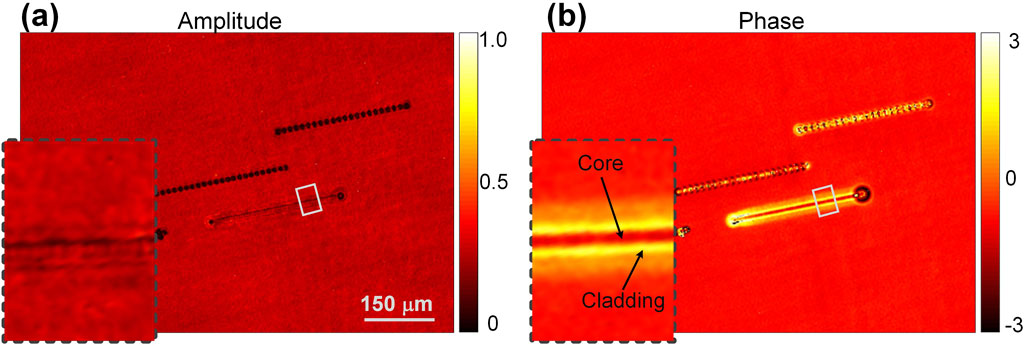
Eventually, SI-LDHM was applied to inspect waveguides fabricated in a silica glass plate. With a single line scan of a focused femtosecond laser over a crystal bulk, the structures with channel geometry were produced [28]. Refractive index (RI) distribution is one of the essential parameters of waveguides. Yet, due to their transparency, conventional optical microscopy can not visualize the waveguides’ structure, let alone quantitatively inspect their 3D RI distribution. By contrast, SI-LDHM manages to provide both the amplitude image and phase image of the waveguides. Compared to the amplitude image in Figure 4A, the phase image in Figure 4B has higher contrast. Notably, it is found from the phase image that the core of the waveguide has a higher RI than the cladding. Such RI distribution was induced by silica expansion from the center to the periphery of the scanned line due to the heating effect. The average power, repetition rate, and scanning speed of the femtosecond laser should be controlled delicately; otherwise, it will lead to the failure of waveguide fabrication (the two black-dotted lines in Figure 4A are failed waveguides due to over-burning of the laser). The above investigation implies that SI-LDHM provides a versatile way for high-throughput waveguide inspection.

Figure 4. SI-LDHM imaging of laser-fabricated waveguide in a glass plate. (A) Reconstructed amplitude image. (B) Reconstructed phase image. The insets in (A) and (B) show a magnified subregion of the waveguide, indicated by the white boxes.
4 Discussion
In summary, a structured-illumination lensless digital holographic microscopy (SI-LDHM) for high-throughput QPM imaging is presented. SI-LDHM utilizes a spatial light modulator (SLM) to generate 24 groups of fringe patterns (8 orientations × 3 phase shifts) for illumination and records the self-interference patterns of the object wave under different SIs. Utilizing the feature that the real and twin images have an opposite defocusing distance, a clean image reconstruction is obtained by refocusing each object wave along the +1st diffraction order of the SI and averaging them for all the orientations of SIs. In this study, SI-LDHM with eight groups of SIs was demonstrated for DHM imaging of a micro-ruler. Eight independent SI yield a reduction of speckle noise by a factor of 2.8 (i.e.,
In the future, iterative projection methods [29] and unified compressive phase retrieval frameworks with both physical constraints and sparsity priors [30] can be further used for reconstruction of SI-LDHM with sub-pixel resolution. Furthermore, 3D refractive index map can be achieved by incorporating the optical diffraction tomography (ODT) reconstruction concept [31] into SI-LDHM.
Data availability statement
The original contributions presented in the study are included in the article/supplementary material, further inquiries can be directed to the corresponding authors.
Author contributions
JZ: Data curation, Formal Analysis, Investigation, Writing–original draft. XG: Data curation, Writing–original draft. YM: Data curation, Writing–review and editing. KW: Data curation, Writing–review and editing. SA: Formal Analysis, Writing–review and editing, Validation. XW: Validation, Writing–review and editing. PG (7th author): Validation, Writing–review and editing. JQ: Validation, Writing–review and editing. CZ: Funding acquisition, Validation, Writing–original draft. PG (10th author): Funding acquisition, Investigation, Methodology, Supervision, Writing–original draft.
Funding
The authors declare financial support was received for the research, authorship, and/or publication of this article. This work was supported by National Natural Science Foundation of China (62075177, 62105251); the Key Research and Development Program of Shaanxi (2024GH-ZDXM-05); National Key Research and Development Program of China (2021YFF0700303); the Natural Science Basic Research Program of Shaanxi (Program Nos 2023-JC-YB-518, 2022JQ-122, 2023-JC-QN-0731). The Fundamental Research Funds for the Central Universities (QTZX23024, QTZX23013, XJS222803, QTZX23008, ZYTS24093 and XJSJ23137).
Conflict of interest
The authors declare that the research was conducted in the absence of any commercial or financial relationships that could be construed as a potential conflict of interest.
The authors declared that they were an editorial board member of Frontiers, at the time of submission. This had no impact on the peer review process and the final decision.
Publisher’s note
All claims expressed in this article are solely those of the authors and do not necessarily represent those of their affiliated organizations, or those of the publisher, the editors and the reviewers. Any product that may be evaluated in this article, or claim that may be made by its manufacturer, is not guaranteed or endorsed by the publisher.
References
1. Kim MK. Principles and techniques of digital holographic microscopy. SPIE Rev (2010) 1:018005. doi:10.1117/6.0000006
2. Mann CJ, Yu L, Lo CM, Kim MK. High-resolution quantitative phase-contrast microscopy by digital holography. Opt Express (2005) 13:8693–8. doi:10.1364/opex.13.008693
3. Gao P, Yuan C. Resolution enhancement of digital holographic microscopy via synthetic aperture: a review. Light: Adv Manuf (2022) 3:105. doi:10.37188/lam.2022.006
4. Gao P, Pedrini G, Osten W. Structured illumination for resolution enhancement and autofocusing in digital holographic microscopy. Opt Lett (2013) 38:1328–30. doi:10.1364/ol.38.001328
5. Emery Y, Cuche E, Marquet F, Aspert N, Marquet P, Kuhn J, et al. Digital holography microscopy (DHM): fast and robust systems for industrial inspection with interferometer resolution. Proc Spie-int Soc Opt Eng (2005) 5856:930–7. doi:10.1117/12.612670
6. Kebbel V, Hartmann HJ, Jüptner WP. Application of digital holographic microscopy for inspection of micro-optical components, optical measurement systems for industrial inspection II: application in industrial design. Proc SPIE (2001) 4398:189–98. doi:10.1117/12.445551
7. Yamaguchi I, Kato J, Ohta S, Mizuno J. Image formation in phase-shifting digital holography and applications to microscopy. Appl Opt (2001) 40:6177–86. doi:10.1364/ao.40.006177
8. Emery Y, Cuche E, Colomb T, Depeursinge C, Rappaz B, Marquet P, et al. DHM (digital holography microscope) for imaging cells. J Phys Conf Ser (2007) 61:1317–21. doi:10.1088/1742-6596/61/1/260
9. Marquet P, Rappaz B, Magistretti PJ, Cuche E, Emery Y, Colomb T, et al. Digital holographic microscopy: a noninvasive contrast imaging technique allowing quantitative visualization of living cells with subwavelength axial accuracy. Opt Lett (2005) 30:468–70. doi:10.1364/ol.30.000468
10. Carl D, Kemper B, Wernicke G, Bally G. Parameter-optimized digital holographic microscope for high-resolution living-cell analysis. Appl Opt (2004) 43:6536–44. doi:10.1364/ao.43.006536
11. Dubois F, Yourassowsky C, Monnom O, Legros JC, Debeir O, Ham PV, et al. Digital holographic microscopy for the three-dimensional dynamic analysis of in vitro cancer cell migration. J Biomed Opt (2006) 11:054032. doi:10.1117/1.2357174
12. Toy MF, Richard S, Kühn J, Franco-Obregón A, Egli M, Depeursinge C. Enhanced robustness digital holographic microscopy for demanding environment of space biology. Biomed Opt Express (2012) 3:313–26. doi:10.1364/boe.3.000313
13. Popescu G, Ikeda T, Goda K, Best-Popescu CA, Laposata M, Manley S, et al. Optical measurement of cell membrane tension. Phys Rev Lett (2006) 97:218101. doi:10.1103/physrevlett.97.218101
14. Zhang J, Dai S, Ma C, Xi T, Di J, Zhao J. A review of common-path off-axis digital holography: towards high stable optical instrument manufacturing. Light: Adv Manuf (2021) 2:1. doi:10.37188/lam.2021.023
15. Medecki H, Tejnil E, Goldberg KA, Bokor J. Phase-shifting point diffraction interferometer. Opt Lett (1996) 21:1526–8. doi:10.1364/ol.21.001526
16. Popescu G, Ikeda T, Dasari RR, Feld MS. Diffraction phase microscopy for quantifying cell structure and dynamics. Opt Lett (2006) 31:775–7. doi:10.1364/ol.31.000775
17. Gao P, Harder I, Nercissian V, Mantel K, Yao B. Phase-shifting point-diffraction interferometry with common-path and in-line configuration for microscopy. Opt Lett (2010) 35:712–4. doi:10.1364/ol.35.000712
18. Zhang M, Ma Y, Wang Y, Wen K, Zheng J, Liu L, et al. Polarization grating based on diffraction phase microscopy for quantitative phase imaging of paramecia. Opt Express (2020) 28:29775–87. doi:10.1364/oe.404289
19. Liu R, Wen K, Li J, Ma Y, Zheng J, An S, et al. Multi-harmonic structured illumination-based optical diffraction tomography. Appl Opt (2023) 62:9199–206. doi:10.1364/ao.508138
20. Chowdhury S, Eldridge WJ, Wax A, Izatt J. Refractive index tomography with structured illumination. Optica (2017) 4:537–45. doi:10.1364/optica.4.000537
21. Choi S, Lee S, Lee T, Ji H, Park H, Im D, et al. World smallest 200Mp CMOS Image Sensor with 0.56μm pixel equipped with novel Deep Trench Isolation structure for better sensitivity and higher CG (2023). Available from: https://imagesensors.org/Past%20Workshops/2023%20Workshop/2023%20Papers/R13.pdf (Accessed on May 22, 2023).
22. Luo W, Greenbaum A, Zhang Y, Ozcan A. Synthetic aperture-based on-chip microscopy. Light Sci Appl (2015) 4:e261. doi:10.1038/lsa.2015.34
23. Wu X, Sun J, Chen Y, Wei J, Chen Q, Poon T, et al. Wavelength-scanning pixel-super-resolved lens-free on-chip quantitative phase microscopy with a color image sensor. Apl Photon (2024) 9:016111. doi:10.1063/5.0175672
24. Greenbaum A, Luo W, Su TW, Gorocs Z, Xue L, Isikman SO, et al. Imaging without lenses: achievements and remaining challenges of wide-field on-chip microscopy. Nat Methods (2012) 9:889–95. doi:10.1038/nmeth.2114
25. Zhang J, Sun J, Chen Q, Li J, Zuo C. Adaptive pixel-super-resolved lensfree in-line digital holography for wide-field on-chip microscopy. Sci Rep (2017) 7:11777. doi:10.1038/s41598-017-11715-x
26. Bhattacharya NGK. Cube beam-splitter interferometer for phase shifting interferometry. J Opt (2009) 38:191–8. doi:10.1007/s12596-009-0017-6
27. Gao P, Yao B, Harder I, Min J, Guo R, Zheng J, et al. Parallel two-step phase-shifting digital holograph microscopy based on a grating pair. J OPT SOC AM A (2011) 28:434–40. doi:10.1364/josaa.28.000434
28. Lv J, Cheng Y, Yuan W, Hao X, Chen F. Three-dimensional femtosecond laser fabrication of waveguide beam splitters in LiNbO3 crystal. Opt Mater Express (2015) 5:1274–80. doi:10.1364/ome.5.001274
29. Gao P, Pedrini G, Osten W. Phase retrieval with resolution enhancement by using structured illumination. Opt Lett (2013) 38:5204–7. doi:10.1364/ol.38.005204
30. Gao Y, Cao L. Iterative projection meets sparsity regularization: towards practical single-shot quantitative phase imaging with in-line holography. Light: Adv Manuf (2023) 4:1–53. doi:10.37188/lam.2023.006
Keywords: quantitative phase microscopy (QPM), lensless digital holographic microscopy (LDHM), structured illumination, spatial light modulator, resolution enhancement
Citation: Zheng J, Guo X, Ma Y, Wen K, An S, Wang X, Gao P, Qian J, Zuo C and Gao P (2024) Structured illumination lensless digital holographic microscopy (SI-LDHM). Front. Phys. 12:1485687. doi: 10.3389/fphy.2024.1485687
Received: 24 August 2024; Accepted: 10 September 2024;
Published: 27 September 2024.
Edited by:
Xinzhong Li, Henan University of Science and Technology, ChinaReviewed by:
Anwar Hussain, COMSATS University, PakistanJiwei Zhang, Northwestern Polytechnical University, China
Liyong Ren, Shaanxi Normal University, China
Copyright © 2024 Zheng, Guo, Ma, Wen, An, Wang, Gao, Qian, Zuo and Gao. This is an open-access article distributed under the terms of the Creative Commons Attribution License (CC BY). The use, distribution or reproduction in other forums is permitted, provided the original author(s) and the copyright owner(s) are credited and that the original publication in this journal is cited, in accordance with accepted academic practice. No use, distribution or reproduction is permitted which does not comply with these terms.
*Correspondence: Chao Zuo, enVvY2hhb0BuanVzdC5lZHUuY24=; Peng Gao, cGVuZy5nYW9AeGlkaWFuLmVkdS5jbg==
 Juanjuan Zheng
 Xuhong Guo1,2,3
 Ying Ma
 Sha An
 Peng Gao
 Chao Zuo
 Peng Gao