 Yun Zhou
 Jian Qiao
 Nan Yan1,2
 Liyan Dai
 Yuehu Pu
95% of researchers rate our articles as excellent or good
Learn more about the work of our research integrity team to safeguard the quality of each article we publish.
Find out more
ORIGINAL RESEARCH article
Front. Phys. , 06 June 2024
Sec. Medical Physics and Imaging
Volume 12 - 2024 | https://doi.org/10.3389/fphy.2024.1395997
This article is part of the Research Topic Physical, Biological, Clinical, and Methodological Advances in Particle Therapy View all 7 articles
Medical accelerators have been widely used in tumor radiation therapy. Accurate isocenter coincidence between treatment beams and imaging systems is critical for image-guided radiation therapy (IGRT). We propose a method utilizing a phantom with marker spheres to detect the Nine Degrees of Freedom (9-DOF) in the system’s geometric model to assess isocenter coincidence between the treatment beams and the kV cone-beam computed tomography (CBCT). The phantom was initially aligned with the accelerator. Subsequently, the projections of the treatment and CBCT beams’ were acquired separately with full gantry rotation. By analyzing the marker spheres’ position in both the treatment beam and CBCT beam projections, the 9-DOF parameters were calculated. A comparison with a Winston-Lutz-based system was performed. Then, the analysis revealed imprecise circular trajectories with noticeable random deviations in the rotations of both the treatment beams and CBCT. The isocenter deviations for the treatment beams and CBCT were 0.18 mm (X), −0.49 mm (Y), and −0.35 mm (Z) after trajectories fitting, respectively. The rotational planes of the two systems exhibited a pinch angle of 0.0235°. This proposed method offers a quantitative assessment of the geometric pose of the source and the detector panel, and the isocenter coincidence of the treatment beams and imaging systems of an accelerator at each gantry angle.
Cone-beam computed tomography (CBCT) is a 3D imaging technique that is widely used in medical accelerator-based image-guided radiation therapy (IGRT) to improve patient positioning accuracy [1–3]. For example, in a medical linear accelerator, compared to the electronic portal imaging devices (EPID) installed on the opposite side of the treatment beam, CBCT images based on kV X-rays provide clearer visualization of the treatment area and surrounding tissues, thereby enhancing the localization accuracy [4–6]. With the increasing reliance on IGRT in clinical practice, there is a growing need for improved accuracy in IGRT [7].
The AAPM TG142 report [8] recommends that the isocenter coincidence of the CBCT imaging system and the treatment beam system should be checked daily. For stereotactic body radiotherapy (SBRT), the deviation between the CBCT image center and the rotation center of the treatment beam should not exceed 1 mm.
In the field of radiation therapy, the Winston-Lutz test is a widely used method to verify the isocenter coincidence. In this method, a small metallic ball phantom is positioned at the linac isocenter defined by the lasers of the treatment room, and the ball is then irradiated with several beams at different gantry angles. The measured distances for all shots between the center of the ball shadow and the radiation field center reveal isocenter movements.
Yoo et al. developed a more easier method for detecting the isocenter coincidence between CBCT imaging and treatment beam [9]. This method involves placing a cubic model at the isocenter using indoor lasers and light field crosshairs, and then calculating the deviation of the two centers using the CBCT imaging [10, 11]. Some major suppliers (e.g., Varian) use a similar method to ensure the coincidence between the CBCT imaging centers and the rotation of the treatment beam based on EPID imaging [12]. In practice, this kind of method is prone to errors due to various factors, including the error in the measurement of the rotation center, the error in the laser light marking of the rotation center, and the error in the actual placement of the marker. Without a more convenient and reliable method, manufacturers emphasize the importance of this prior detection in their system manuals.
The aforementioned methodologies are characterized by their operational simplicity; however, these methods can only detect deviations of the system’s central point in the X, Y, and Z directions, but cannot detect variations in the position of the system’s central point as the gantry angle rotates.
Linear accelerators with onboard CBCT have both an MV treatment beam system and a kV imaging system that can be considered cone beam systems. Therefore, the cone beam geometric calibration method has become a new approach to detecting the rotation center of the CBCT imaging system and the treatment beam system of the linear accelerator. This method has been used in commercial systems such as Varian’s IsoCal [13–15]. To correct the geometric uncertainty in rotation, Cho et al. proposed using an independent coordinate system combined with CBCT images [16]. Yang et al. designed a simpler model that is easier to obtain [17]. Some studies have attempted to apply this theory to measurements of accelerators or accessories, such as treatment couches [18–20]. However, these experiments made a series of assumptions in advance to simplify the range of data collection and computation. These assumptions (such as the rotation of the accelerator beam axis being a fixed `point) simplified the evaluation model and introduced new errors.
In this study, we proposed a cone beam system calibration method based on phantom markers detection, which further improved the proposal of Yang et al. by eliminating the dependence on several assumptions in previous methods. We quantitatively evaluated the 9-DOF parameters in the geometric models of the onboard CBCT imaging system and the treatment beam system of a linear accelerator with the gantry rotation. and calculated the deviation between the CBCT image center and the rotation center of the treatment beam under the non-ideal circularity of the rotation trajectory, the non-ideal stiffness of the rotating structure, and the non-ideal repeatability of the rotation. We compared the detection results of the proposed method in this study with those obtained from the Winston-Lutz-based detection method.
For linear accelerators equipped with onboard CBCT, both the MV treatment beam system and the kV imaging beam system can be considered as cone beam systems [21] (Figure 1).
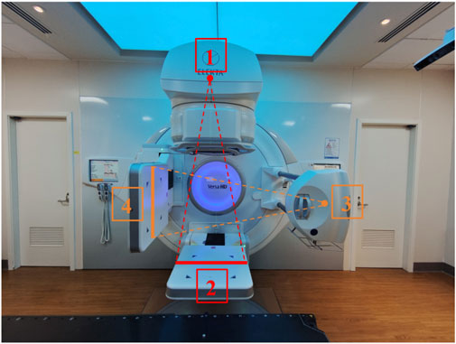
Figure 1. Schematic diagram of the MV treatment beam system and the kV imaging beam system of a linear accelerator. (1) MV treatment beam source; (2) MV treatment beam detector; (3) kV imaging beam source; (4) kV imaging beam detector.
The center consistency of the MV treatment beam and the kV imaging can be considered as the geometric center consistency of two cone beam systems. In the IEC 61217 standard, the angle and direction of the ray source for a cone beam system are not defined as it is usually assumed to be a point source. The position of the source is defined by three parameters: SourceOffsetX, SourceOffsetY, and SourceOffsetZ. On the other hand, the detector’s position and orientation require six parameters, including translations in three axial directions (DetectorOffsetX, DetectorOffsetY, DetectorOffsetZ) and rotation around the three axes (the rotation angle of the detector around X axis, the rotation angle of the detector around Y axis (GantryAngle), the rotation angle of the detector around Z axis) (Figure 2; Table 1). Consequently, the 9-DOF parametric methodology, when applied to the coordinate systems of linear accelerators, provides an accurate characterization of the spatial orientation and positioning for both the MV treatment beam system and the kV imaging system.
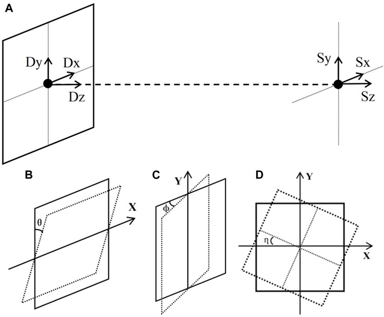
Figure 2. A schematic diagram of the system with 9-DOF: (A) translation of the source and detector in three axial directions, (B) rotation of the detector around X axis, (C) rotation of the detector around the Y axis, and (D) rotation of the detector around the Z axis.
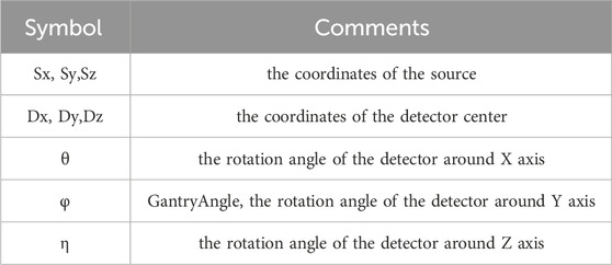
Table 1. Notation of the 9-DOF parameters.
In some CBCT algorithms, such as the FDK algorithm, there are explicit requirements for the geometry of the system. For an standard cone beam system with circular source-detector trajectories, the following conditions must always be met [22] (Figure 3):
a. The line connecting the source and the center of the flat panel detector (Magnification Axis) must intersect and be perpendicular to the rotation axis and the plane of the flat panel detector;
b. The rotation axis projection on the detector plane must be parallel to the column pixel direction;
c. The rotation axis must remain stable during rotation.
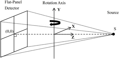
Figure 3. Diagram of an ideal cone beam system.
In practice, to simplify the calculation, several assumptions are usually made on the conditions mentioned above. For instance, the Varian IsoCal program assumes that the rotation center is an ideal point, the line passing through the source point, the rotation center and the flat panel detector are perpendicular to the flat panel detector. Moreover, Inaccuracies in source and detector movements are all corrected by the physical detector position (kV and MV) [23].
To accurately describe and evaluate the non-ideal trajectory movement of a cone beam system, this study employs a 9-DOF approach to define the geometry of the radiation source and detector. This study adopts a prerequisite assumption that the posture of the detector and its relative position to the radiation source does not change during the entire gantry rotation. The mathematical principles and relevant formulas of the implementation method are briefly derived as follows.
By the data presented in Figure 4; Table 2, it can be deduced that for any arbitrary point “g” existing within the spatial domain, the corresponding projected point “r” can be accurately determined in Eq. 1:
where
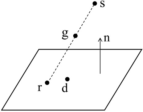
Figure 4. Diagram of the projection of an arbitrary point in space onto a flat panel detector.
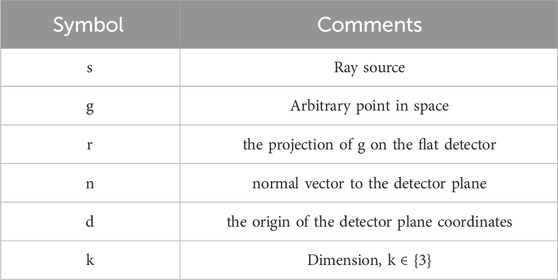
Table 2. Symbol definition.
Therefore, it can be derived as in Eq. 2:
Define the space of all possible geometries as G in Eqs 3, 4 :
where
and
The projection r of point g in a geometric space
This problem can be deformed as an optimization problem in Eq. 5:
The optimization problem can be solved via the Levenberg-Marquardt method for Rn,d, S, i.e., to obtain the coefficients of 9-DOF of the geometric system.
In this study, the linear accelerator used was the Versa HD (Elekta AB, Stockholm, Sweden). This accelerator is equipped with an onboard MV X-ray flat panel detector EPID, along with the corresponding imaging software (iViewGT), as well as an onboard kV imaging system (XVI). All movements and directions in this study follow the IEC 61217 standard.
The calibration phantom used in the study was the Varian IsoCal phantom, which is a hollow cylinder with a diameter and length of 23 cm and has 16 spherical tungsten markers, each with a diameter of 4 mm. The coordinates of the markers are precisely known, and the average position of all markers is defined as the center of the phantom. This center is also known as the origin of the phantom coordinate system.
The IsoCal phantom was fixed on the VersaHD treatment couch and adjusted according to the laser light indication to align its center with the accelerator’s isocenter.
The XVI volumetric scanning imaging software bundled with the VersaHD was used to set the scanning parameters for this study. The FlexMap scanning protocol included in the XVI software was chosen. The Full Fan scanning mode was utilized with a gantry rotation angle range from 180° to 180° (clockwise). Following the kV CBCT scanning, a self-developed program was used to read the projection files in “.his” format and identify and track the markers in the phantom projection images (Figure 5). The coordinates of each marker in the projection image were then extracted.

Figure 5. The markers in the phantom projection images were identified and tracked.
After the kV CBCT scanning, the IsoCal phantom remained in the same position on the treatment couch. Due to the field number limitation in each plan of Monaco (Elekta AB, Stockholm, Sweden, version 5.1), four plans were created in Monaco, each containing 90 fields. One field was created for each gantry angle, with a field size of 25 × 25 cm and each field set as 2MU. The four plans were exported to iviewGT, and the corresponding fields were created in the iviewGT software. The value for the number of IMRT segments was set to 90, and the corresponding plans were executed in single exposure mode to acquire EPID images at the corresponding angles. After irradiation, the DICOM image files of the IsoCal phantom at each angle were exported from the MV treatment beam imaging software iViewGT, which is built into the accelerator. The same method as in the kV CBCT detection was used to identify and track the markers of the IsoCal phantom in the MV treatment beam images. The coordinates of each marker in the MV treatment beam projection image were extracted. The 9-DOF parameters between the kV imaging system and the MV treatment beam system at each gantry angle, as well as the change in the position of the center of the phantom relative to the flat panel detector, were optimized and solved according to the formulas in Section 2.1.
The control experiment adopted the Winston-Lutz detection workflow, using a Ball-bearing (BB) phantom (Elekta Synergy Basic Calibration Kit, MRT 15991) and DoseLab image analysis software (Varian, version 6.80). The difference in the rotation center was demonstrated by comparing the position of the fixed-in-space phantom center on different images.
The experiment first set the gantry angle of the accelerator to 0° and the field size to 5 cm × 5 cm. A 3 cm diameter cone was mounted on the treatment head. EPID images of the cone were collected at 0° and 180° of the treatment head, and the cone position was adjusted to make the cone field coincide at 0° and 180° of the treatment head.
Then, the BB phantom was placed at the rotation center of the treatment beam indicated by the laser light in the treatment room of the accelerator. MV treatment beam EPID images were collected at gantry angles of 0°, 90°, 180°, and 270°. Doselab software was used to analyze the four-angle images to calculate the 3D spatial displacement of the BB spheres. Based on the calculation results, the BB spheres’ position was adjusted until the 3D spatial displacement of the BB spheres was minimized (usually less than 1 mm). This center of the BB spheres was considered to be the rotation center of the MV treatment beam.
With the BB spheres’ position fixed, a CBCT scan was performed under the same conditions. The reconstructed image was registered to the system’s preset reference image, which had already been calibrated for the kV imaging system’s center in advance. The registration deviation detected represents the discrepancy between the kV image center and the rotation center of the MV treatment beam.
In this study, the VersaHD accelerator’s gantry rotation range is 0°–360°. The 9-DOF parameters of the kV and MV beam system geometric model were measured within this range in the IEC 61217 coordinate system. Figure 6 demonstrates the trajectories of the IsoCal phantom’s center point relative to the centers of both the kV and MV detectors during gantry rotation, with the paths forming irregular circular areas.
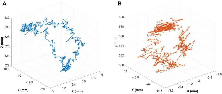
Figure 6. Trajectory of the Phantom Center to the detectors: (A) kV Detector; (B) MV Detector.
The study measured the angle changes of the MV/kV detector as it rotated around the X-axis and Z-axis during gantry rotation. The findings indicated that the two sets of angle changes agreed, and a 90° interval separated the angles (Figure 7).
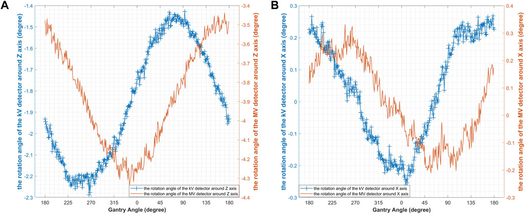
Figure 7. The rotation of the kV/MV detectors: (A) the rotation angle of the detector around Z axis; (B) the rotation angle of the detector around X axis.
During the gantry rotation, the center point of the kV/MV detectors showed similar displacements in the X and Y directions within the detector plane. However, at 90° and 270°, the center point of the MV detector showed more noticeable fluctuations in the Y direction (Figure 8).
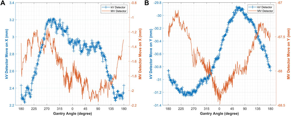
Figure 8. The displacement of the kV/MV detector centers in the detector plane: (A) in the X direction; (B) in the Y direction.
The detection results showed that the kV/MV beam source trajectory was not an ideal circle, but rather showed a certain amount of random jitter deviation (Figures 9A, B). As stated in Section 2.1, this study assumed a stationary relationship between the source and the flat-panel detector in the CBCT system, with no relative motion between them. Therefore, the curves in Figures 9C, D are smooth and ideal. The difference in the kV/MV beam source trajectory after fitting was shown in Table 3.
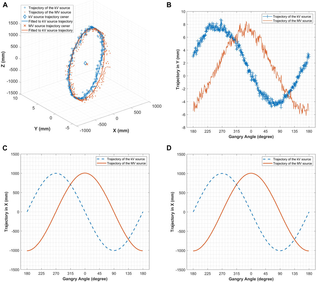
Figure 9. (A) Trajectory of the kV&MV source; (B) Trajectory of the kV&MV source in the Y direction; (C) Trajectory of the kV/MV source in the X direction; (D) Trajectory of the kV&MV source in the Z direction.
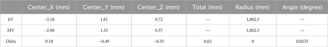
Table 3. The difference in the MV/kV beam source trajectory after fitting.
In this study, we obtained MV treatment beam images of the BB spheres at four basic gantry angles (Figure 10). The shift between the BB spheres and the beam center at each gantry angle was calculated in Doselab (Table 4). The shifts of the BB spheres’ position in the X, Y, and Z directions were +0.05 mm, −0.02 mm, and +0.04 mm, respectively.
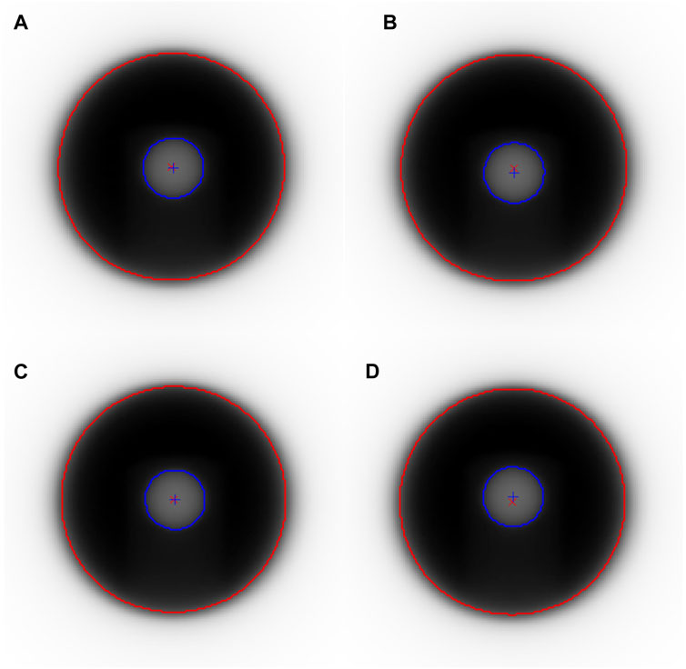
Figure 10. MV treatment beam images of the Winston-Lutz phantom at four basic gantry angles: (A) 0°, (B) 90°, (C) 180°, (D) 270°.
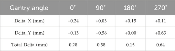
Table 4. Shift between the MV treatment beam center and the BB spheres’ center at four basic gantry angles.
The CBCT images of the BB spheres were obtained during the detection process and then registered with the reference image in XVI (Figure 11). The BB spheres shifted by −0.2 mm, −0.1 mm, and +0.2 mm in the X, Y, and Z directions, respectively. There was an overall shift of 0.30 mm between the kV/MV centers.
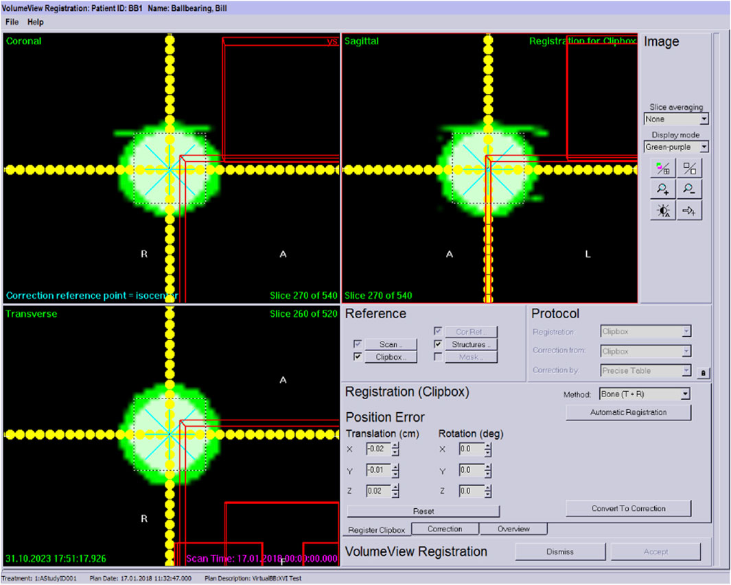
Figure 11. Calculation of the deviation of the ball from the reference position in in XVI.
In this study, we found that the beam source trajectory (Figure 9) is not entirely in the X-Z plane, but has a certain tilt. The possible reason is that the IsoCal phantom placement is not precise enough, that is, the axis of the calibration phantom does not coincide with the Y axis perfectly, but has a certain tilt angle, resulting in a certain angle of the beam source trajectory.
We also found that the beam source rotation trajectory is not a regular circle, and there is no ideal rotation center. In this study, we fitted a circle to the beam source trajectory. The center of the circle is used as the center of the beam system to calculate the consistency between kV/MV centers. However, it is worth noting that there is no universally accepted method for measuring the rotation center of the treatment beam for a non-ideal gantry system of an accelerator. The above method of calculating the rotation center of the beam system by fitting the circular trajectory of the beam source is only one of the methods used in this study. In future studies, other methods can also be tried, such as using the center point of the trajectory of the change in the position of the phantom center relative to the flat panel detector as the center point to calculate the center of the beam system.
During the rotation of the gantry, the KV/MV beam source does not remain in the same plane. This means that for the MV treatment beam system, there is a deviation in the treatment beam at each angle. In other words, the treatment beam angle and center will be offset. This issue needs to be taken into consideration in certain clinical scenarios [24].
During gantry rotation, this study found that the MV detector center point showed more noticeable fluctuations in the Y direction at 90° and 270°. The Winston-Lutz measurements also revealed that the MV beam center and BB spheres’ center had larger deviations at 90° and 270°. The results of the two detection methods were in good agreement. However, for the kV/MV center consistency, the Winston-Lutz measurement results can only provide an overall numerical value of the deviation, and cannot reflect the difference with the change of gantry angle. This method can be used to quantitatively measure the difference between kV/MV at different gantry angles based on the 9-DOF parameters of the beam system geometry model.
This method uses the calibration principle of a cone beam system with 9-DOFparameters to evaluate the system’s geometry model quantitatively. Compared with the Varian IsoCal calibration algorithm, this method does not require several assumptions, such as the rotation center being an ideal point. These assumptions simplify the geometric system model and assume that the gantry rotation of the cone beam system is ideal. However, in practice, considering the purpose of QA work, the error caused by this simplification is worth considering, especially for equipment that has been in use for a long time. This method abandons these assumptions and analyzes the irregular biases of the system, such as the non-coplanar rotation of kV/MV and the non-standard circular trajectory of rotation. By detecting the actual trajectory of kV/MV rotation and fitting the motion trajectory, this method calculates the deviation of kV/MV beam rotation, taking into account the actual situation of the equipment. It is worth noting that this study still adopts an assumption, where the source and the flat-panel detector in the cone-beam X-ray system remain relatively stationary, with no relative motion between them. This assumption necessitates a high level of rigidity in the accelerator gantry. When the gantry lacks sufficient rigidity, this assumption will also introduce new errors.
The existing detection methods based on the Winston-Lutz phantom also have similar assumptions, such as the ideal circular trajectory of kV/MV rotation, and the accurate coordinates of the MV treatment beam rotation center can be ideally obtained by repeatedly adjusting the BB ball position. However, in actual operation, these assumptions cannot be guaranteed and realized. For instance, in Section 3.2, there is a certain deviation between the MV treatment beam center and the BB sphere center for each gantry angle, which cannot be precisely determined. In contrast, this method does not require the phantom center to be precisely located at the treatment beam center. Additionally, the technique has the advantage of allowing the image center to be directly correlated with the radiation center, etc., without passing through an indoor laser or the crosshair of light fields, which makes the clinical operation more convenient.
In this study, the CBCT system and the MV treatment beam system were fixed on the same gantry. However, in clinical practice, many particle accelerators are installed independently of the CBCT system, which is different from electron linacs. For this application scenario, since the coordinates of the markers in the IsoCal phantom are precisely known, the average position of all markers is defined as the center of the phantom, which is also the origin of the phantom coordinate system. All 9DOF parameters detected in this study can be converted into this phantom coordinate system. Therefore, this method can also be applied to other particle accelerators equipped with independent CBCT systems.
In this study, We proposed a method utilizing a phantom with marker spheres to detect the 9-DOF in the system’s geometric model to quantitatively assess isocenter coincidence between the MV treatment beams and the kV CBCT at various gantry angles. The research revealed that the trajectory of the source rotation exhibits a certain degree of random deviation. Furthermore, the motion of the kV/MV radiation sources does not remain in the same plane throughout the gantry rotation. The results obtained using the 9-DOF optimization method in this study were consistent with those of the Winston-Lutz measurements. This method abandons these assumptions of idealized system motion but retained one assumption that the source and the detector within the cone-beam system remain relatively stationary. This avenue of investigation may be pursued in future studies to achieve a higher degree of precision in the measurement of the equipment’s actual performance.
The raw data supporting the conclusion of this article will be made available by the authors, without undue reservation.
YZ: Conceptualization, Data curation, Methodology, Writing–original draft, Writing–review and editing. JQ: Formal Analysis, Investigation, Writing–original draft, Writing–review and editing. NY: Software, Validation, Visualization, Writing–review and editing. LD: Data curation, Formal Analysis, Validation, Writing–review and editing. YP: Funding acquisition, Supervision, Writing–review and editing.
The author(s) declare that financial support was received for the research, authorship, and/or publication of this article. This research was supported by the National Key Research and Development Program of China (Grant No. 2016YFC0105400).
The authors declare that the research was conducted in the absence of any commercial or financial relationships that could be construed as a potential conflict of interest.
All claims expressed in this article are solely those of the authors and do not necessarily represent those of their affiliated organizations, or those of the publisher, the editors and the reviewers. Any product that may be evaluated in this article, or claim that may be made by its manufacturer, is not guaranteed or endorsed by the publisher.
1. Fahrig R, Jaffray DA, Sechopoulos I, Webster Stayman J. Flat-panel conebeam CT in the clinic: history and current state. J Med Imaging (Bellingham). J Med Imaging (Bellingham) (2021) 8(5):052115. doi:10.1117/1.JMI.8.5.052115
2. Srinivasan K, Mohammadi M, Shepherd J. Applications of linac-mounted kilovoltage Cone-beam Computed Tomography in modern radiation therapy: a review. Pol J Radiol (2014) 79:181–93. doi:10.12659/PJR.890745
3. Liu H, Schaal D, Curry H, Clark R, Magliari A, Kupelian P, et al. Review of cone beam computed tomography based online adaptive radiotherapy: current trend and future direction. Radiat Oncol (2023) 18(1):144. doi:10.1186/s13014-023-02340-2
4. El Naqa I, Pogue BW, Zhang R, Oraiqat I, Parodi K. Image guidance for FLASH radiotherapy. Med Phys (2022) 49(6):4109–22. doi:10.1002/mp.15662
5. Herrick M, Penfold S, Santos A, Hickson K. A systematic review of volumetric image guidance in proton therapy. Phys Eng Sci Med (2023) 46(3):963–75. doi:10.1007/s13246-023-01294-9
6. Lane SA, Slater JM, Yang GY. Image-guided proton therapy: a comprehensive review. Cancers (Basel) (2023) 15(9):2555. doi:10.3390/cancers15092555
7. Grégoire V, Guckenberger M, Haustermans K, Lagendijk JJW, Ménard C, Pötter R, et al. Image guidance in radiation therapy for better cure of cancer. Mol Oncol (2020) 14(7):1470–91. doi:10.1002/1878-0261.12751
8. Klein EE, Hanley J, Bayouth J, Yin F-F, Simon W, Dresser S, et al. Task Group 142 report: quality assurance of medical acceleratorsa. Med Phys (2009) 36:4197–212. doi:10.1118/1.3190392
9. Yoo S, Kim GY, Hammoud R, Elder E, Pawlicki T, Guan H, et al. A quality assurance program for the on-board imagers. Med Phys (2006) 33(11):4431–47. doi:10.1118/1.2362872
10. Brezovich IA, Popple RA, Duan J, Shen S, Wu X, Benhabib S, et al. A novel phantom and procedure providing submillimeter accuracy in daily QA tests of accelerators used for stereotactic radiosurgery. J Appl Clin Med Phys (2016) 17(4):246–53. doi:10.1120/jacmp.v17i4.6295
11. Kang H, Patel R, Roeske JC. Efficient quality assurance method with automated data acquisition of a single phantom setup to determine radiation and imaging isocenter congruence. J Appl Clin Med Phys (2019) 20(10):127–33. doi:10.1002/acm2.12723
12. Mao W, Lee L, Xing L. Development of a QA phantom and automated analysis tool for geometric quality assurance of on-board MV and kV x-ray imaging systems. Med Phys (2008) 35(4):1497–506. doi:10.1118/1.2885719
13. Clivio A, Vanetti E, Rose S, Nicolini G, Belosi MF, Cozzi L, et al. Evaluation of the machine performance check application for TrueBeam linac. Radiat Oncol (2015) 10:97. doi:10.1186/s13014-015-0381-0
14. Barnes MP, Greer PB. Evaluation of the truebeam machine performance check (MPC) geometric checks for daily IGRT geometric accuracy quality assurance. J Appl Clin Med Phys (2017) 18(3):200–6. doi:10.1002/acm2.12064
15. Du W, Gao S, Jiang W, Kudchadker RJ. Independent evaluation of the effectiveness of IsoCal in improving image center accuracy on Varian TrueBeam and Clinac machines. J Appl Clin Med Phys (2018) 19(5):483–90. doi:10.1002/acm2.12402
16. Cho Y, Moseley DJ, Siewerdsen JH, Jaffray DA. Accurate technique for complete geometric calibration of cone-beam computed tomography systems. Med Phys (2005) 32(4):968–83. doi:10.1118/1.1869652
17. Yang H, Kang K, Xing Y. Geometry calibration method for a cone-beam CT system. Med Phys (2017) 44(5):1692–706. doi:10.1002/mp.12163
18. Gao S, Du W, Balter P, Munro P, Jeung A. Evaluation of IsoCal geometric calibration system for Varian linacs equipped with on-board imager and electronic portal imaging device imaging systems. J Appl Clin Med Phys (2014) 15(3):164–81. doi:10.1120/jacmp.v15i3.4688
19. Zhang Q, Driewer J, Wang S, Li S, Zhu X, Zheng D, et al. Accuracy evaluation of a six-degree-of-freedom couch using cone beam CT and IsoCal phantom with an in-house algorithm. Med Phys (2017) 44:3888–98. doi:10.1002/mp.12342
20. Dumas JL, Fawzi M, Masset H, Losa S, Dal R, Pierrat N, et al. Independent 6D quality assurance of stereotactic radiotherapy repositioning on linacs. Cancer Radiother (2020) 24(3):199–205. doi:10.1016/j.canrad.2020.01.005
21. Malajovich I, Teo BK, Petroccia H, Metz JM, Dong L, Li T. Characterization of the megavoltage cone-beam computed tomography (MV-CBCT) system on HalcyonTM for IGRT: image quality benchmark, clinical performance, and organ doses. Front Oncol (2019) 9:496. doi:10.3389/fonc.2019.00496
22. Ferrucci M, Leach R, Giusca C, Carmignato S, Dewulf W. Towards geometrical calibration of x-ray computed tomography systems - a review. Meas Sci Technol (2015) 26:092003. doi:10.1088/0957-0233/26/9/092003
23. Varian Medical Systems TrueBeam administrators guide. Palo Alto, CA: Varian Medical Systems (2018). p. 325–10. version: P1011693-004-D.
Keywords: radiation therapy (radiotherapy), medical accelerator, isocenter coincidence, quality assurance, cone-beam computed tomography (CBCT)
Citation: Zhou Y, Qiao J, Yan N, Dai L and Pu Y (2024) A nine-degree-of-freedom optimization-based method to evaluate the isocenter coincidence of the treatment beams and image system of a medical accelerator. Front. Phys. 12:1395997. doi: 10.3389/fphy.2024.1395997
Received: 05 March 2024; Accepted: 20 May 2024;
Published: 06 June 2024.
Edited by:
Dousatsu Sakata, Osaka University, JapanReviewed by:
Haijiao Shang, RaySearch Medical Device Co., Ltd., ChinaCopyright © 2024 Zhou, Qiao, Yan, Dai and Pu. This is an open-access article distributed under the terms of the Creative Commons Attribution License (CC BY). The use, distribution or reproduction in other forums is permitted, provided the original author(s) and the copyright owner(s) are credited and that the original publication in this journal is cited, in accordance with accepted academic practice. No use, distribution or reproduction is permitted which does not comply with these terms.
*Correspondence: Yuehu Pu, cHV5dWVodUAxNjMuY29t
†These authors have contributed equally to this work and share senior authorship
Disclaimer: All claims expressed in this article are solely those of the authors and do not necessarily represent those of their affiliated organizations, or those of the publisher, the editors and the reviewers. Any product that may be evaluated in this article or claim that may be made by its manufacturer is not guaranteed or endorsed by the publisher.
Research integrity at Frontiers
Learn more about the work of our research integrity team to safeguard the quality of each article we publish.