 Amir Weinberg1*
 Avraham Gover1*
 Ariel Nause2Aharon Friedman2Reuven Ianconescu3Andrew Fisher4Pietro Musumeci4Atsushi Fukasawa4
 James Rosenzweig4
- 1School of Electrical Engineering—Physical Electronics, Center of Light-Matter Interaction, Tel Aviv University, Tel Aviv, Israel
- 2The Schlesinger Center for Compact Accelerators and Radiation Sources, Ariel University, Ariel, Israel
- 3Shenkar College, Ramat Gan, Israel
- 4Department of Physics and Astronomy, University of California, Los Angles, United States
We present theoretical analysis and design considerations of a THz superradiant FEL. We derive analytical expressions for the spectral parameter of THz radiation, emitted superradiantly in a rectangular waveguide using a Longitudinal Section Magnetic mode expansion. The results compare well with numerical simulations using UCLA GPTFEL code. GPT simulations of the accelerator e-beam transport show that the chirp provided by a hybrid photocathode RF gun, can produce tight bunching at the undulator site below
1 Introduction
Bunched beam superradiance is the coherent spontaneous radiation emission of a bunch of electrons, taking place when the bunch duration
Here we extend earlier theory of bunched-beam superradiance [1, 3], and apply it to evaluate and optimize the spectrum and energy of a compact THz FEL shown schematically in Figure 1. This experimental setup is based on the design of the Israeli hybrid 6 MeV photocathode RF gun [4]. A picosecond electron bunch emitted from the cathode is accelerated and chirped within the short (0.6 m) hybrid accelerator, and then compressed through free drift compression, velocity bunching (ballistic compression) [5–7] along a 3.4 m beamline to
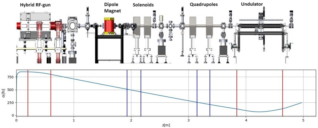
Figure 1. Top: A sketch of the ORGAD (optically excited RF GUN accelerator device) accelerator. Bottom: bunch duration evolution along the ORGAD FEL beamline.
2 Emission energy and spectrum of a superradiant waveguide FEL
We present here the formulation for calculating the spectral energy and total emission energy of superradiant waveguide FEL. Using the formulation of [1], the spectral energy per emitted radiation mode q in the case of a perfectly bunched electron beam (zero length bunch—farther down we generalize to a finite length bunch) is:
and its integrated energy is:
These equations are valid for any complete orthogonal mode expansion in free space or in a waveguide. In the case of conventional free space FEL
Where
The spectral energy of the radiation mode (Eq. (1)) depends on frequency through the tunning parameter
The formulation so far is valid for any waveguide mode expansion. We consider an FEL configuration based on a rectangular waveguide and planar undulator polarized in the y direction (see Figure 2). For this configuration we find it most productive to use a waveguide expansion set of LSM (Longitudinal Section Magnetic) modes [11]. This is an alternative to the conventional TE TM mode expansion. The LSEx modes (characterized by Ex = 0) and LSMx modes (characterized by Hx = 0), are a complete set of orthogonal modes, equivalent to the {TE, TM} mode expansion. In a planar undulator configuration, shown in Figure 2, the wiggling of the electron beam, and thus the excitation current, are in the x dimension. Therefore, in the {LSEx, LSMx} expansion, we can eliminate the LSEx modes, since they cannot be excited by the beam current, and thus we manage to describe the radiation field in terms of half the number of modes of the degenerate {TE, TM} mode expansion. We therefore calculate only the excitation of the LSMx modes given by [11]:
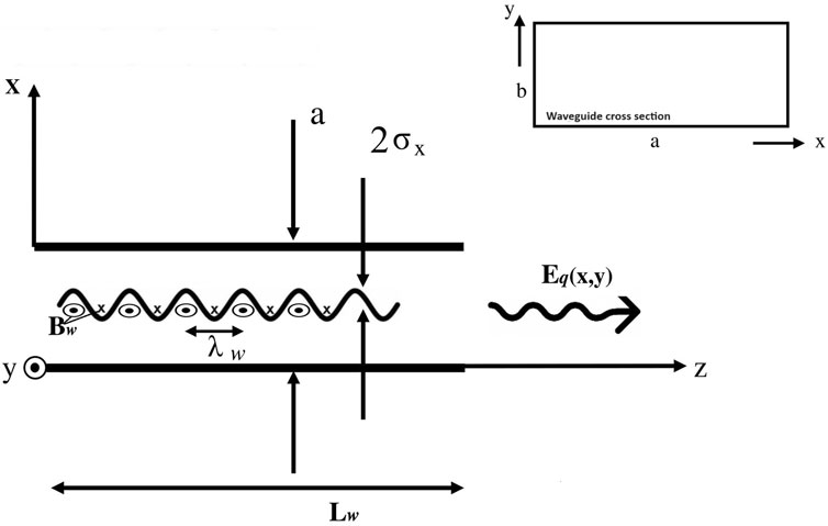
Figure 2. Rectangular waveguide coordinates and dimensions, (a) waveguide width, (b) waveguide height, Lw—undulator length.
Substituting the fields of the excitable modes (5) in the excitation Equation 1, we calculated the spectral energy of the emitted radiation for the first lower 9 modes of the waveguide. For the designed example parameters, listed in Table 1, the radiation energies of these modes are listed in the third row of Table 2.
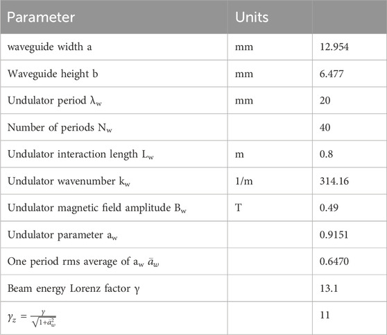
Table 1. Parameters of the ORGAD superradiant FEL.
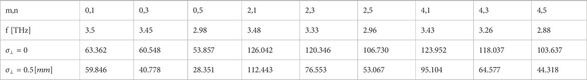
Table 2. Emitted Energy W[nJ] computed from Eq. 2. The mode indices (m,n) (Eq. 6) correspond to the mode numbers in the wide (horizontal) x dimension and the height (vertical) y dimension of the rectangular waveguide respectably (see Figure 2). The third row corresponds to an ideal case of a delta function transverse beam profile. The fourth row—corresponds to a Gaussian transverse beam profile. In either case the bunch is ideally narrow in the longitudinal dimension.
In practice the beam transverse dimension and its longitudinal bunching are not ideal. We considered here also the case of a beam of finite transverse and longitudinal dimensions assuming gaussian distribution. The effects of the transverse distribution of the beam can be taken into account by convolving Eq. (1) with the normalized transverse distribution of the beam profile, which gets modified because of the (x0, y0) dependances of the effective mode area
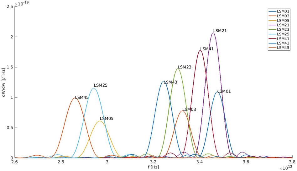
Figure 3. Spectral Energy of the first 9 excitable LSM modes for E = 6.2Mev, computed from Eq. 1 using the parameters of Table 1, The beam width and time duration are
The total emitted superradiant energy and spectral energy of the modes would be reduced also by the finite longitudinal dimension of the beam. This is a result of destructive interference between the radiation wave packets emitted by distributed electrons when the short bunch condition is not satisfied. The spectral energy and total superradiant radiant energy are reduced by a bunching factor relative to the ideal zero-length bunch (eq. 1,2). For a bunch longitudinal profile represented by a Gaussian distribution of standard deviation
and the mode energy is:
The bunching factor Eq. 7 is plotted in Figure 4 as a function of the emission frequency for various values of
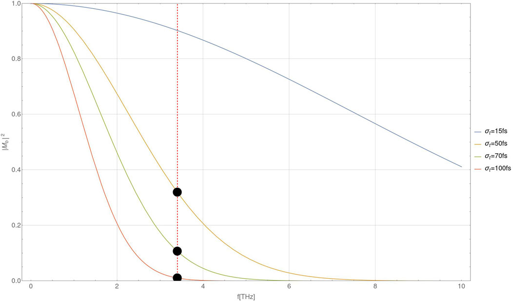
Figure 4. Bunching factor plotted as a function of frequency for different bunch durations σt.
3 Numerical computation of superradiance
We compare the above analytical calculation results for the superradiant energy emission with numerical computations based on the UCLA GPTFEL code [12, 13] for a rectangular waveguide model. We performed the computations for the parameters of the ORGAD FEL configuration (Table 1). The comparison is made for the fundamental mode of the rectangular waveguide TE01 which is identical with the LSM01 mode used in the analytical calculation. Figure 5 displays the numerically simulated spectral energy of the mode TE01. The frequency spectrum in this model is presented in turns of longitudinal modes [12], and the beam at the entrance to the undulator is modeled in terms of a gaussian distribution. The spectral energy distribution computed by the numerical code is in good agreement with the corresponding curve of mode LSM01.

Figure 5. Simulated spectral energy of the LSM01 mode computed with UCLA GPTFEL for a nearly ideal short and narrow bunch of length σz = 5um (bunch duration σt = 16 fs), bunch transverse size
In Table 3 we compare the analytically calculated emission energy of the fundamental mode energy to the numerical simulation results for different values of the standard deviation of the beam bunch distribution σt. The calculated bunching factor (Eq. 7) and reduced emission energy (Eq. (8)) are listed in the third and fourth columns of Table 3. The numerically computed results, listed in the fifth column, are about 50% higher. They also indicate diminishing of the emission energy of the fundamental mode (centered at f = 3.4 THz) for
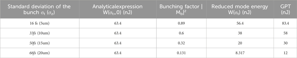
Table 3. Comparison between analytical calculation and GPTFEL code computation of mode LSM01 (TE01).
4 Phase space (γ-t) dynamics of beam compression
Since the high frequency operation of the superradiant terahertz source is limited by the size (duration) of the electron beam bunch within the length of the undulator, it is important to control the free drift self-compression of the beam from the gun to the undulator and attempt to minimize the bunch duration nearly at the center of the undulator. In Figure 6 we show the evolution in phase space of a Gaussian beam starting from the buncher (modulator) section of the gun, right after full acceleration, and then going through free drift transport up to the undulator. In our linear beam transport model, the phase-space area of the beam is conserved under linear transport transformations.
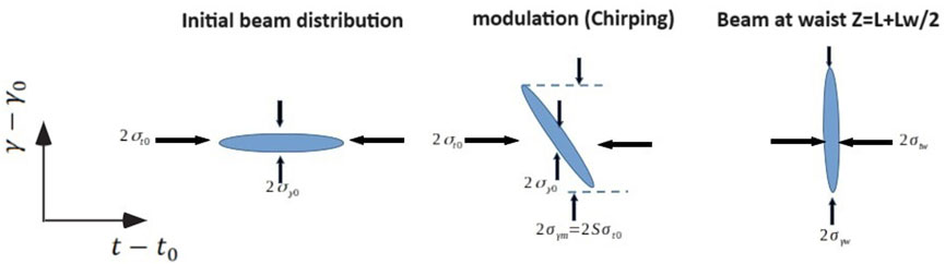
Figure 6. The evolution in
We model the initial distribution in γ-t phase-space of the accelerated beam (before bunching) in terms of a Gaussian function:
We Consider beam transport from the accelerator to the center of the undulator. In a linear phase-space dynamics model the beam phase-space distribution stretches in the time dimension according to
The energy dispersion compaction parameter R56 is the result of free drift along a distance L from the gun to the undulator entrance and a subsequent drift within periodic magnetic field along half the length of the undulator:
where B┴ is the undulator magnetic field. Substituting Eq. (12) in Eq. (11) we obtain:
We receive an oblique ellipse contour:
Requiring attainment of a minimal duration bunch at the center of the undulator, we observe that this happens when the ellipse, keeping constant area, becomes erect. This corresponds to a requirement that the mixed term in Eq. 15 nulls. This corresponds to a condition for R56:
or alternatively, in order for the beam waist to fall inside the undulator one needs to satisfy a condition on the modulation (chirp rate) coefficient:
At the waist, the ellipse is erect:
where
Substituting (17) or (16) in (15), the radii of the erect ellipse are found to be:
Since we expect compression -
We conclude that the bunch duration at the waist is limited by the intrinsic energy spread (defined as the uncorrelated beam energy spread at its waist before modulation).
Note that in the framework of the linear model, the phase space area is conserved throughout the beam transport from the gun to the wiggler,
5 Bunch transport and compression in the configuration of the ORGAD accelerator
We follow the phase space evolution of the beam for the example of the ORGAD accelerator using the linear transformation phase-space model. Bear in mind that this model is limited, does not include space-charge effects and nonlinear phase space evolution. Also, it is assumed that the amplitude of the superradiant radiation field is low (below saturation), and the beam dynamics is independent of the emitted radiation, namely, the emitted radiation does not act back on the particles. Therefore the linear model can serve only as a preliminary guide for the design of the superradiant FEL, and further on it should be checked and compared to the results of detailed GPT transport simulations that include consideration of space-charge effects. Such simulations are shown in Supplementary Appendix A for the ORGAD parameters where the beam transport was adjusted to produce a ribbon beam in the undulator in order to reduce space-charge effects.
We calculate the compaction factor from the end of the gun to the center of the undulator. This is given as a sum of the free drift compaction factor from the gun to the undulator and the compaction factor of half the length of the undulator R56(a)+R(b)56 = R56. As derived in Supplementary Appendix C, for γ0 = 13.1 and Le = 3.24[m]
For these parameters we calculate the modulation coefficient desired for attaining a waist at the center of the undulator. The starting parameters for the linear phase-space evolution are taken from the GPT simulation of the gun section (see Supplementary Appendix A): the intrinsic energy spread is σγ0 = 0.01 (σE0 = 5 keV), and the beam bunch size at the gun is σt0 = 1[ps]. Using Eq. (17), this results in S = 1.77*1011[1/sec], which is fairly consistent with the computed chirp rate shown in the last panel of Supplementary Appendix Figure SA1. According to eq. 21 and eq. (20), these parameters should enable attaining a beam waist of
This result of an ideal linear transport model is an underestimate relative to the result of a full GPT simulations with the parameters of the ORGAD hybrid photocathode gun. The GPT simulation along the entire beam transport results in a beam bunch waist σtw = 70[fs] at the center of the undulator (see lower part of Figure 1 and Supplementary Appendix A). This is slightly bigger than the estimate of the linear model.
In order to compare the beam size evolution in the linear phase space model to the numerical GPT simulation we trace back the phase-space ellipse evolution from the waist location at the center of the undulator backward.
We start from Eq. 14 and assume that the phase-space ellipse is erect at the waist point in the middle of the undulator
The compaction factor dependence on z starting from the exit of the gun z = 0 is (Supplementary Appendix C):
where η is the step function, and
From here we derive the size of the beam (the projection of the ellipse on the time axis t [7]:
This curve is shown in Figure 7 for the earlier computed parameters
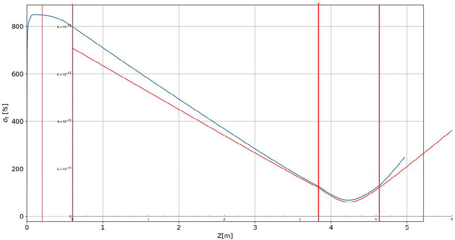
Figure 7. Plot of the bunch size evolution σt(z) traced back to the gun exit from the waist position at the center of the undulator using Eq. 24 (see red curve). GPT simulation plot of the bunch size evolution from the gun cathode and beyond the undulator (blue curve), is overlayed over the analytical calculation plot. The first vertical red lines mark the acceleration and chirping sections of the gun, the last two red lines mark the undulator section.
In Figure 7 we also show the corresponding results of GPT simulations for the same parameters overlayed over the same coordinate axis. The simulated curve deviates approximately by 20% at the start of the drift section (exit of the gun). The discrepancy is attributed to space charge expansion of the bunch along the drift section and in the undulator.
6 Conclusion
Bunched beam superradiance is an attractive concept for attaining intense THz radiation in a compact FEL scheme [1, 3, 14–16]. Here we presented theory and design consideration of a superradiant waveguide FEL based on a compact (60 cm long) hybrid photocathode RF gun. For the configuration of the ORGAD accelerator, an 80 cm long undulator and a modest beam bunch charge of 20 pC, we predict for an ideally short bunch, emission of about W = 60 nJ radiation at the fundamental transverse radiation mode LSM01 at frequency 3.4 THz and nearly 1 μJ in 9 transverse modes in the frequency range 2.5–3.5 THz. To attain these energies, one is required to attain compression of the beam to short duration -
It is instructive to compare the parameters of the superradiant THz FEL design to the alternative scheme of enhancing spontaneous undulator radiation by SASE [17]. The superradiance enhancement factor relative to spontaneous emission is N = Q/e, the number of electrons in the beam. This factor is 108 for Q = 20 pC. Larger enhancement factors are attainable by the SASE scheme, but this requires much longer undulator, higher beam energy and higher beam charge [17, 18]. In PITZ the measured terahertz energy was two orders of magnitude (tens of
We presented an analytical model evaluation for the evaluation of superradiannt energy and spectral distribution [1, 3], and compared the results to numerical computations using UCLA GPTFEL code. We found fair agreement between the radiation spectrum and the integrated radiation energy per mode computed using the code and using the analytical expression.
We presented a linear model for tracing the beam compression dynamics in energy-time phase-space evolution from the electron gun through free drift up to and within the undulator. This model is a useful tool for preliminary design of a superradiant FEL, however, it has limited validity because it does not take into consideration space-charge effects and nonlinear distortion of phase-space trajectories transformation. The model helped to recognize that the attainment of short bunches in the undulator and high frequency operation is limited also by the intrinsic (uncorrelated) energy spread of the gun. In realistic design, the predictions of the linear phase-space evolution model must be checked by numerical simulations that take into account apace charge effects. In the present paper we backed up the analytical model design example by GPT numerical computation that include space-charge effects. For the presented design example space charge effect deviations of the beam trajectories were moderate (20%).
Within the validity limits of the linear model, we found that the minimal temporal waist size of the beam
The bunch duration in the ORGAD Accelerator design is also bound by the energy spread of the photocathode gun. GPT simulations in the gun section indicate intrinsic energy spread in the gun of ∼5 keV for a beam of charge of 20 pC that should be attributed to space charge effects in the early acceleration stages in the gun. We conclude that for the design example parameters, both the intrinsic energy of the gun (due to space charge effects) and space charge effects in the undulator limit the attainment of beam compression below
Data availability statement
The original contributions presented in the study are included in the article/Supplementary Material, further inquiries can be directed to the corresponding author.
Author contributions
AW: Investigation, Writing–original draft. AG: Supervision, Writing–original draft. AN: Supervision, Writing–review and editing. AhF: Methodology, Writing–review and editing. RI: Validation, Writing–review and editing. AnF: Software, Writing–review and editing. PM: Methodology, Software, Writing–review and editing. AtF: Writing–review and editing. JR: Methodology, Writing–review and editing.
Funding
The author(s) declare financial support was received for the research, authorship, and/or publication of this article. We acknowledge support by the Israel Science Foundation through grant 1705/22.
Conflict of interest
The authors declare that the research was conducted in the absence of any commercial or financial relationships that could be construed as a potential conflict of interest.
Publisher’s note
All claims expressed in this article are solely those of the authors and do not necessarily represent those of their affiliated organizations, or those of the publisher, the editors and the reviewers. Any product that may be evaluated in this article, or claim that may be made by its manufacturer, is not guaranteed or endorsed by the publisher.
Supplementary material
The Supplementary Material for this article can be found online at: https://www.frontiersin.org/articles/10.3389/fphy.2024.1385314/full#supplementary-material
References
1. Gover A, Ianconsescu R, Friedman A, Emma C, Sudar N, Musumeci P, et al. Superradiant and stimulated-superradiant emission of bunched electron beams. Rev Mod Phys. (2019) 91:035003. doi:10.1103/revmodphys.91.035003
2. Dicke RH. Coherence in spontaneous radiation processes. Phys Rev (1954) 93(99):99–110. doi:10.1103/physrev.93.99
3. Gover A. Superradiant and stimulated-superradiant emission in prebunched electron-beam radiators. I. Formulation. Phys Rev St-accl Beams (2005) 8:030701. doi:10.1103/physrevstab.8.030701
4. Nause A, Friedman A, Weinberg A, Borodin D, Feigin L, Fukasawa A, et al. 6 MeV novel hybrid (standing wave - traveling wave) photo-cathode electron gun for a THz superradiant FEL. NIM-A (2021) 1010. doi:10.1016/j.nima.2021.165547
5. Ferrario M, Alesini D, Bacci A, Bellaveglia M, Boni R, Boscolo M, et al. Experimental demonstration of emittance compensation with velocity bunching. Phys Rev Lett (2010) 104(5):054801. doi:10.1103/physrevlett.104.054801
6. Anderson S, Musumeci P, Rosenzweig JB, Brown WJ, England RJ, Ferrario M, et al. Velocity bunching of high-brightness electron beams. Phys Rev St-accel Beams (2005) 8(1):014401. doi:10.1103/physrevstab.8.014401
8. Weinberg A, Nause A. Dogleg design for an MeV ultra-fast electron diffraction beamline for the hybrid photo-emitted RF GUN at ariel university. NIM-A (2021) 989. doi:10.1016/j.nima.2020.164952
9. Weinberg A, Nause A. Beam-line optimization based on realistic electron-optics 3D field-maps implementation provides high-quality e-beam via a dogleg section. Phys Plasmas (2022) 29. doi:10.1063/5.0087858
10. Jerby E, Gover A. Investigation of the gain regimes and gain parameters of the free electron laser dispersion equation. IEEE J Quan Electron (1985) 21(7):1041–58. doi:10.1109/jqe.1985.1072748
12. Fisher A, Musumeci P, Van der Geer S. Self-consistent numerical approach to track particles in free electron laser interaction with electromagnetic field modes. Phys Rev Acc ad Beams (2020) 23(11):110702. doi:10.1103/physrevaccelbeams.23.110702
13. Musumeci P, Fisher A, Van Der Geer B, Nanni EA, Snively EC, Gover A. A Waveguide-Based High efficiency superradiant FEL operating in the THz regime. In: FEL2019, hamburg (2019).
14. Siriwan K, Shuya C, Heishun Z, Toshiteru K, Hideaki O. Manipulation of laser distribution to mitigate the space-charge effect for improving the performance of a THz coherent undulator radiation source. particles MDPI (2018) 1(1):238–52. doi:10.3390/particles1010018
15. Siriwn K, Heishun Z, Shuya C, Toshiteru K, Hideaki O. Properties of THz coherent undulator radiation generated from a compact accelerator source at Kyoto University. Rev Sci Inst (2019) 90(10):103307. doi:10.1063/1.5110342
16. Joshi V, Karmakar J, Kumar N, Karmakar B. Theoretical and simulation study of ′comb′ electron beam and THz generation (2018). Available from: https://arxiv.org/abs/1806.04338 (Accessed 12 June 2018).
17. Krasilnikov M, Aboulbanine Z, Asoyan A, Davtyan H, Boonpornprasert P, R G. First lasing of the THz SASE FEL at PITZ. In: FEL22, trieste (2022).
18. Krasilnikov M, Aboulbanine Z, Adhikari G, Aftab N, Asoyan A, Davtyan H. THz SASE FEL AT PITZ: LASING AT A WAVELENGTH OF 100μm. In: IPAC, venice (2023).
19. Prat E, Lucas TG, Dijkstal P, Di Mitri S, Ferrari E, et al. Energy spread blowup by intrabeam scattering and microbunching at the SwissFEL injector. Phys Rev Accel Beams (2022) 25(10):104401. doi:10.1103/physrevaccelbeams.25.104401
20. Prat E, Dijkstal P, Ferrari E, Malyzhenkov A, Reiche S. High-resolution dispersion-based measurement of the electron beam energy spread. Phys Rev Accel Beams (2020) 23:090701. doi:10.1103/physrevaccelbeams.23.090701
21. Tomin S, Zagorodnov I, Decking W, Golubeva N, Scholz M. Accurate measurement of uncorrelated energy spread in electron beam. Phys Rev Accel Beams (2021) 24(6):064201. doi:10.1103/physrevaccelbeams.24.064201
Keywords: FEL, superradiance, waveguide LSM modes, GPTFEL, THz, hybrid photocathode gun, coherent undulator radiation, bunched beam
Citation: Weinberg A, Gover A, Nause A, Friedman A, Ianconescu R, Fisher A, Musumeci P, Fukasawa A and Rosenzweig J (2024) Theory and design consideration of a THz superradiant waveguide FEL. Front. Phys. 12:1385314. doi: 10.3389/fphy.2024.1385314
Received: 12 February 2024; Accepted: 02 April 2024;
Published: 24 April 2024.
Edited by:
Javier Resta López, University of Valencia, SpainReviewed by:
John Wesley Lewellen, Los Alamos National Laboratory (DOE), United StatesMikhail Krasilnikov, Helmholtz Association of German Research Centres (HZ), Germany
Copyright © 2024 Weinberg, Gover, Nause, Friedman, Ianconescu, Fisher, Musumeci, Fukasawa and Rosenzweig. This is an open-access article distributed under the terms of the Creative Commons Attribution License (CC BY). The use, distribution or reproduction in other forums is permitted, provided the original author(s) and the copyright owner(s) are credited and that the original publication in this journal is cited, in accordance with accepted academic practice. No use, distribution or reproduction is permitted which does not comply with these terms.
*Correspondence: Amir Weinberg, YW1pcndlQHRhdWV4LnRhdS5hYy5pbA==; Avraham Gover, Z292ZXJAZW5nLnRhdS5hYy5pbA==