
94% of researchers rate our articles as excellent or good
Learn more about the work of our research integrity team to safeguard the quality of each article we publish.
Find out more
ORIGINAL RESEARCH article
Front. Phys., 23 May 2024
Sec. High-Energy and Astroparticle Physics
Volume 12 - 2024 | https://doi.org/10.3389/fphy.2024.1384415
This article is part of the Research TopicNew Developments In The Quest For Discovering Axions And Axion-like Particles.View all 6 articles
 K. Altenmüller1*
 J. F. Castel1
 S. Cebrián1
 T. Dafni1D. Díez-Ibañez1
 A. Ezquerro1E. Ferrer-Ribas2J. Galan1
 J. Galindo1,3J. A. García1A. Giganon2C. Goblin2I. G. Irastorza1C. Loiseau2G. Luzón1X. F. Navick2C. Margalejo1H. Mirallas1
 L. Obis1A. Ortiz de Solórzano1
 T. Papaevangelou2O. Pérez1A. Quintana1,2J. Ruz1
 J. K. Vogel1,4
In this paper we present measurements performed with a Micromegas X-ray detector setup. The detector is a prototype in the context of the BabyIAXO helioscope, which is under construction to search for an emission of the hypothetical axion particle from the Sun. An important component of such a helioscope is a low background X-ray detector with a high efficiency in the 1–10 keV energy range. The goal of the measurement was to study techniques for background discrimination. In addition to common techniques we used a multi-layer veto system designed to tag cosmic-ray induced neutron background. Over an effective time of 52 days, a background level of 8.6 × 10⁻⁷ counts keV−1 cm−2 s−1 was reached in a laboratory at above ground level. This is the lowest background level achieved at surface level. In this paper we present the experimental setup, show simulations of the neutron-induced background, and demonstrate the process to identify background signals in the data. Finally, prospects to reach lower background levels down to 10–7 counts keV−1 cm−2 s−1 are discussed.
The measurements presented in this paper were performed with a prototype detector for the BabyIAXO helioscope. BabyIAXO will search for an emission of the hypothetical axion particle from the Sun [1,2]. The axion is a theoretically well motivated candidate particle for the dark matter. It arises as a solution to the strong CP problem through the Peccei-Quinn mechanism [3,4]. Generic axions couple to photons, which permits the transformation of axions and photons into each other via the Primakoff effect. Non-hadronic axion models predict additionally a significant coupling of axions to electrons (e.g., [5,6]). After simple models that predict relatively heavy axions were ruled out by previous experiments, the axion—if it exists—has to be very light with a low interaction strength, which makes it a well suited dark matter candidate [7,8]. Several anomalous astrophysical observations hint at the existence of axions: axion-photon oscillations could explain both the unexpectedly fast cooling of white dwarfs and the transparency of the Universe to very high-energy gamma rays [9–11]. The region of the parameter space motivated by both these hints is partially in reach for a next-generation helioscope like BabyIAXO [1]. BabyIAXO is a fully-fledged helioscope that will explore relevant parameter space, however, it also serves as a prototype for an even larger experiment—IAXO, the International AXion Observatory [2,12]. At the same time, BabyIAXO is the successor of the CERN Axion Solar Telescope (CAST), which took data until the end of 2021 and delivered current benchmark limits over a wide range in the axion parameter space, which are at the same level as astrophysical limits [13].
The principle of an axion helioscope is to use the inverse Primakoff effect to convert solar axions that reach the earth into detectable photons [14]. For this purpose, a strong magnet is aligned with the Sun. Axions passing through the volume of the magnetic field, which contains a high density of virtual photons, can transform into X-ray photons. These photons are then focused by X-ray optics onto low-background detectors [12]. The device-specific characteristics that determine the discovery potential are the strength, length and volume of the magnet, the throughput of the optics and smallness of the focal spot, the efficiency and background level in the energy range of interest in the detector as well as the exposure time tracking the Sun [1]. In this paper, we are discussing only the final component in this chain, the detector.
Computing the expected energy spectrum of solar axions (or the resulting photons) shows us the requirements of this detector. The spectrum of axions produced by the Primakoff effect is a distribution with a peak at
A conceptual sketch of the current BabyIAXO design is shown in Figure 1. For more information, the design is presented in great detail in the paper [1], while a full review of the physics case relevant for BabyIAXO can be found in Ref. [16]. BabyIAXO is expected to be hosted by DESY in Hamburg, its construction has recently started.
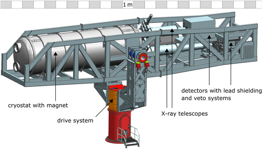
Figure 1. A sketch of the BabyIAXO helioscope. Mounted in a frame on the drive system, one can see the cryostat containing the magnet on the left, connected on the right to the X-ray telescopes and the detectors within their veto-systems. The total length of the helioscope is
The work presented in this paper is about measurements with a Micromegas detector prototype for BabyIAXO, where a novel veto system was utilized to push the background down to an unprecedented level. In the next sections we describe the setup, show simulations of the setup, and then present methods to identify background events. Finally, we present and discuss the achieved background level from measurements in a laboratory at surface.
At CAPA1 of the University of Zaragoza, a Micromegas prototype detector, dubbed IAXO-D0, was installed to take background data in order to characterize it under different conditions and to improve the background rejection. See Figure 2 for photos of the setup. Previously, with similar Micromegas detectors, background levels of 1 × 10⁻⁶ counts keV−1 cm−2 s−1 were demonstrated at surface level at CAST [13]. However, measurements in the underground laboratory at Canfranc2 with a CAST replica detector suggested much lower levels of
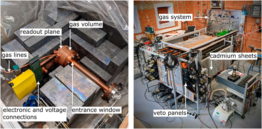
Figure 2. The IAXO-D0 setup. On the left the Micromegas detector within its lead castle. On the right the entire setup including the triple layer veto system.
The Micromegas detector is a gas-filled time projection chamber with a Micromesh Gaseous Structure (Micromegas) readout plane [19]. The volume filled with gas has a depth (drift distance) of 3 cm. On one side, the volume is closed by an entrance window made of 4 μm-thick aluminized mylar, that also serves as cathode at a voltage of ∼ − 750 V. On the other end, the readout covers a surface of 6 × 6 cm2 with 120 strips in each direction. A sketch of the Micromegas detector is shown in Figure 3. The Micromegas readout of IAXO-D0 is produced via the microbulk method using only radiopure copper and Kapton [20]. It includes a mesh that is placed 50 µm above the strips and kept at a voltage between −370 and −390 V. The detector is thus divided in two regions: a drift or conversion region between mesh and cathode, and an amplification region between the mesh and the strip readout, where the latter serves as anode at ground level. The volume is surrounded by rings at intermediate voltages that shape the electric field to improve the drift characteristics.
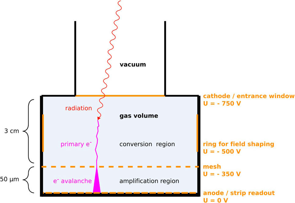
Figure 3. A scheme of the Micromegas detector. The yellow lines mark the electrodes, and their typical voltages are indicated. Note that the dimensions of the conversion and the amplification regions are not to scale.
In the context of the axion search, the energy range of interest (ROI) is 2–7 keV. The lower limit of the energy range is set slightly above the detector threshold. The upper limit is set to 7 keV, because above this energy the expected solar axion flux is negligible and one can evade signals from the 8 keV copper Kα X-ray fluorescence peak (visible in Figure 12). Depending on the gas mixture and pressure used, a detection efficiency of 60%–70% is reached in the ROI. The detector threshold is
In total 57 veto panels were installed. A drawing of the system is shown in Figure 4. The veto panels are made of NE-110. They are second-hand from the 90s and were previously used in a time-of-flight spectrometer [21]. For our setup, the 3 m long panels were cut to the appropriate length of 150 cm or 65 cm. Each panel has a width of 20 cm and thickness of 5 cm. On one end a PMT is connected via a light guide. In between the panels, cadmium sheets of 1 mm thickness were placed. The veto panels were calibrated using the spectrum of atmospheric muons. The energy loss of muons in matter follows a Landau distribution, where the most probable value—the peak—is located at 2 MeV/g cm2. Thus, if the veto panel lies flat, with its 5 cm thickness and a density of
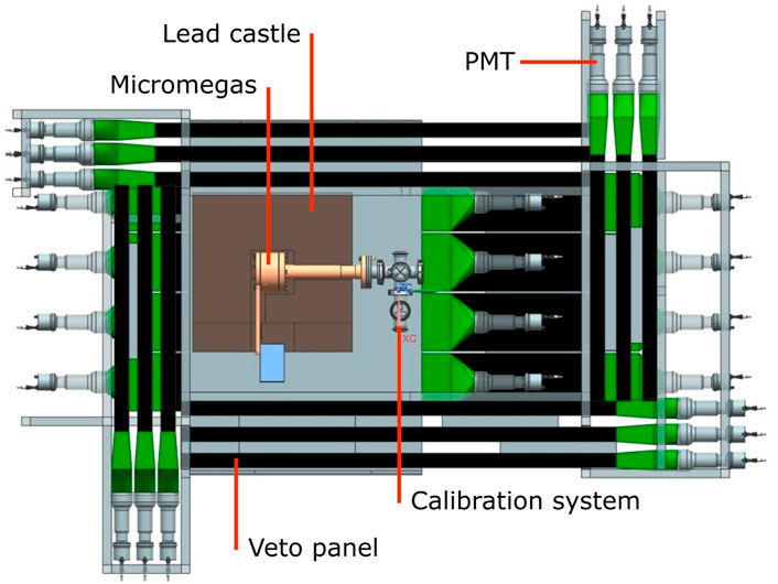
Figure 4. A cutaway of the setup with the triple-layer veto system, seen from the top. The cadmium sheets surrounding the veto panels are not pictured.
The scintillator panels used in this setup were readily available and thus chosen to test this veto system. However, the dedicated veto system for BabyIAXO will be more compact, consist of higher quality scintillator and might feature silicon photomultiplier readouts.
Both the Micromegas and the vetoes are read out by 4 AGET ASICs each. The AGET was developed together by several collaborations of the nuclear physics community, financed by French and American agencies [22]. Each AGET has 64 channels. The shaped detector signals are digitized and stored over an adjustable time window. The analog signal is sampled continuously over 512 bins by a circular buffer. This allows to freely select the delay between the start of the time window and the trigger. Generally, the trigger is set to multiplicity mode, reacting to the sum of the time over threshold of multiple channels. In order to use different readout settings for the Micromegas and the vetoes we use separate FPGAs for each group of AGETs. The FPGAs are the Spartan 6 Model from Xilinx (now AMD). A central trigger and clock module synchronizes the two groups of AGETs. For the Micromegas, the time window should be large enough to collect entire tracks over the 3 cm drift distance. With typical voltage settings, the drift velocity of electrons in the Xe-Ne mixture is about 5 mm/μs, thus an event can take up to 6 μs. During data taking, the time window was set to different values between 10 and 30 μs. The veto readout system is triggered by the Micromegas readout electronics. Whenever the Micromegas registers an event, all veto channels are read out in a 100 μs time window. In relation to this window, the Micromegas trigger is located at 30 μs.
The development of the experiment has been complemented by extensive radiation transport simulations using Geant4 [23]. REST-for-Physics has been used as the software framework to interface with Geant4, and to process the resulting data [24]. A full model of the IAXO-D0 setup including both the Micromegas detector, lead shielding and veto system was created (see Figure 5). The REST-for-Physics libraries allow to process the energy deposits calculated by Geant4 in order to mimic raw signals similar to the ones produced by the physical setup. For this purpose, physical processes as the electron drift and diffusion in the Micromegas, light attenuation in the scintillator, and quenching of nuclear recoils are calculated, and the data accordingly transformed. These signals are then processed in the same way as the data from the experiment, allowing for an accurate comparison of simulation and real data. For this study, we simulated the cosmic-ray induced neutron flux at sea level [25]. Neutrons are of special interest because they can often produce events with a signature similar to axion-induced events: the nuclear recoil induced by a neutron interaction in the detector gas results in a small, symmetric energy deposit with typical energies within the BabyIAXO ROI, similar to an X-ray event [18]. At the same time it is very difficult to shield the detector from this background contribution at surface level so a strategy to tag these events was developed. As described in Section 2, we focus on cosmic-ray induced neutrons, because comparisons of surface and underground measurements with a Micromegas imply that they dominate our background.
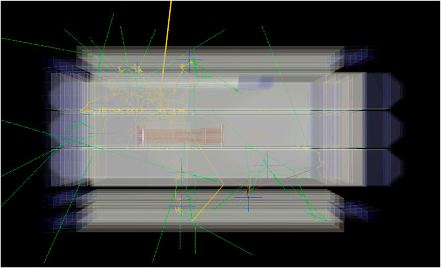
Figure 5. Simulation of a cosmic neutron event. The primary neutron (thick yellow line) enters the setup from above interacting in the lead castle producing multiple secondary lower-energy neutrons (yellow). Some of these neutrons interact with the veto system and after moderation can be captured (blue cross), resulting in the production of gamma rays (green) which can be detected by the veto.
Simulation studies for cosmic-ray induced neutrons result in a raw background level of 8.8 × 10⁻⁶ counts keV−1 cm−2 s−1 on the readout surface for a ROI of 1–10 keV. This background level is further reduced after applying micromegas signal cuts, described in 4.2, to a value of 9.0 × 10⁻⁷ counts keV−1 cm−2 s−1. The background level is strongly dependent on the primary neutron flux assumed in its calculation, which currently has a large uncertainty. In any case, it supports the hypothesis that the cosmic neutrons are the dominating contribution to the remaining background level achieved, e.g., with the Micromegas at CAST, motivating the development of the active shielding system described above, able to tag neutron-induced events.
As already mentioned in Section 2, the muon veto system was used as the base for the cosmic neutron veto. To enhance the capability of detecting cosmic neutrons, the number of plastic scintillators was increased to achieve a three-layer 4π-coverage and cadmium sheets were introduced as neutron capturing material around the scintillators (see Figure 4).
An example of a simulated cosmic neutron event is displayed in Figure 5. All cosmic neutron events follow a similar pattern: a high energy neutron enters the setup from above usually interacting with the lead shielding. These interactions produce a number of secondary neutrons roughly proportional to the primary energy. These secondary neutrons can also multiply if their energy is high enough. The lower energy secondary neutrons gradually lose energy via elastic processes in the shielding and especially in the plastic scintillators, which consist of elements with low atomic number. A background signal can be created, when a neutron scatters within the volume of the Micromegas detector. After losing most of their kinetic energy, the neutrons are captured by the cadmium sheets. The result of this capture is a burst of gamma rays with energies in the order of a few MeV. Since this capture takes place near the scintillators, the gammas produced are used to improve the efficiency of the veto system. The Micromegas itself is protected against these gammas by the lead shielding. The elastic processes of neutrons in the scintillator can also directly produce signals. However, in these nuclear recoils only a fraction of the neutron’s kinetic energy is transferred, and the light yield is additionally quenched to values lower than the one of photon or electron interactions with similar energies, thus many of the signals are expected to be below detection threshold.
Due to the secondary neutrons needing to become thermalized before being captured, there is a delay between the background event in the Micromegas and the multiple neutron captures, as shown in Figure 6. In this plot, the time 0 corresponds to the detection of a signal in the Micromegas, caused by one of the neutrons in the event. Most neutron captures from the same event follow within a time window in the order of 100 μs. This is the required acquisition window for the veto system. Figure 7 shows the multiplicity of veto signals of a neutron event. To calculate the multiplicity, the entire chain from the production of secondary neutrons to the interaction of single gammas in multiple veto panels was taken into account. The threshold of the vetoes was set to 1 MeV3. The bin at 0 corresponds to events, were no neutron was captured. One can see that in most events many vetoes detect a signal, with the multiplicity distribution peaking in the range of 1–6, while it steeply descends for higher values.
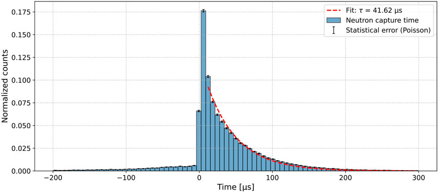
Figure 6. Time of neutron capture in the simulations for cosmic neutron background events. Here t = 0 corresponds to the trigger of the Micromegas detector. A fit to a negative exponential function is displayed.
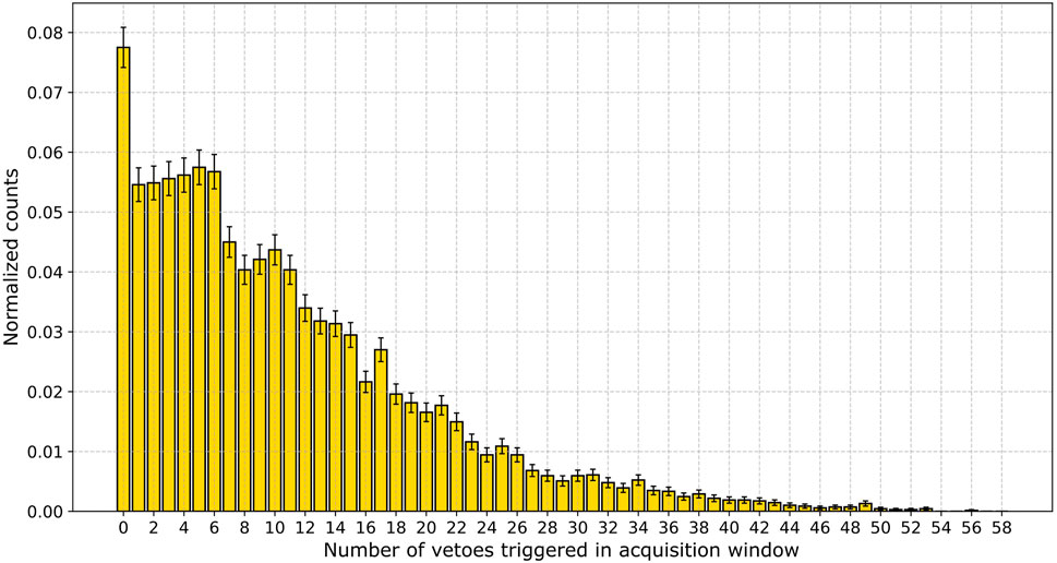
Figure 7. Simulation of the multiplicity–the number of triggered vetoes–for a neutron event. The veto threshold is set to 1 MeV. The counts are shown with their statistical errors.
The data acquired with the Micromegas detector is processed and analyzed using the REST-for-Physics software framework [24]. This software processes the signals from the strips and extracts spectra and 3-dimensional topological information of the charge deposition. The data is processed in three steps using the appropriate REST-for-Physics libraries: during the raw signal analysis noise events are identified and removed, and the signal pulses are isolated; in the detector hits analysis the signals from electronic channels are translated to energy deposits (“hits”) and associated with physical coordinates (X,Y) in the readout geometry; the size of the energy deposit in the Z-coordinate is calculated from the charge collection time and drift velocity, which in turn is calculated with the Garfield++ code [26]; finally, in the track analysis the energy deposits are connected to 3-dimensional tracks by using multiple algorithms to find the shortest path that interconnects energy deposits within an event, adding another level of topological information. The processing generates many observables—per-event information extracted from the data—that are used to define selection criteria for background discrimination.
The signature of an axion-like signal is determined by calibrating the detector with the 5.9 keV X-rays of the 55Fe-source. In general, a low energy X-ray is expected to leave a small, symmetrical charge deposit in the detector. Furthermore, in the context of BabyIAXO, the signals of interest are located in a small spot in the center of the detector readout plane—the focal spot of the telescope. Also the calibration events in the IAXO-D0 setup are centered in a small region of the detector. This collimation is caused by the source distance and the size of the entrance window. This fiducialization improves additionally the background level, as the center of the readout is less affected by radioactive impurities in the detector walls and X-ray fluorescence.
The following observables were used for background discrimination:
• Energy: the cuts are optimized using the 5.9 keV peak of the 55Fe-source. Events within about one sigma around the peak maximum are used, typically corresponding to an energy range of 5.4–6.4 keV
• Position in the readout (X–Y) plane: only events where the mean position of the deposited energy of an event falls within a circle of 9 mm radius in the center of the readout plane are considered. The size of this circle is determined by the spot of the collimated X-rays from the calibration source.
• Number of tracks: the photoabsorption of X-rays is a point like event that is identified as a single track in contrast to background events like charged particle interactions that usually leave multiple tracks.
•
• Sigma balance in X–Y plane: the sigma balance (σX − σY)/(σX + σY) measures the topological symmetry of an event.
• Energy balance: the energy balance (EX − EY)/(EX + EY) is rather similar to the sigma balance, but uses the reconstructed energy.
•
To discriminate background, the data is filtered using the above-mentioned observables. Each cut is either a function of one variable (e.g., the radius of the focal spot) or of two variables (upper and lower limit). The variables depend on the conditions of the measurement and change, for example, with the detector voltage settings, which affect the diffusion and spread of events. The variables have to be optimized such that the filter removes as much as possible background events while preserving calibration data. This optimization is performed via an automatic procedure using the MINUIT2 engine by maximizing the ratio of calibration-to-background events for each cut sequentially. In Figure 8 a dataset is plotted and the applied criteria are shown.
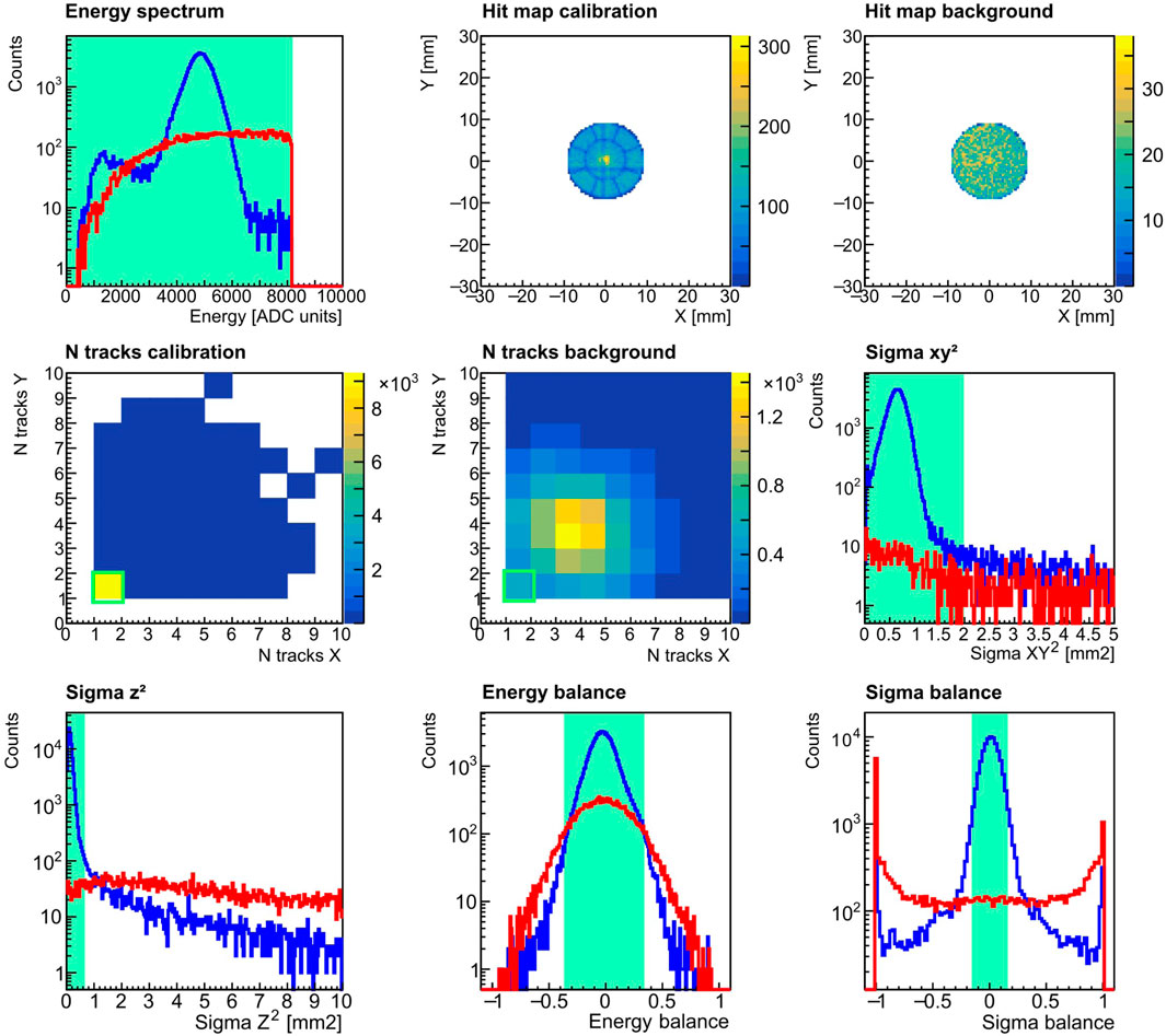
Figure 8. Comparison of data obtained with the 55Fe calibration-source (blue histograms) and background runs (red histograms). The green markings indicate the selection criteria, all events outside the shaded areas are removed from the data. The energy and fiducial cut were already applied. For the number of tracks observable, the best discrimination is achieved by selecting only single-track, i.e., point-like events. Furthermore, as shown in the “sigma” observables, events with small spread in all spatial coordinates are selected. For the balance observables, we select events in a small interval around zero, corresponding to symmetric energy deposits.
A muon cut is applied using data from the veto system. The relevant time window can be easily identified by observing an excess of signals in temporal correlation with the Micromegas trigger. This can be seen in Figure 9. The muon cut removes events which contain a veto signal within a time window of 16 μs around the Micromegas trigger and with an energy of more than 5 MeV.
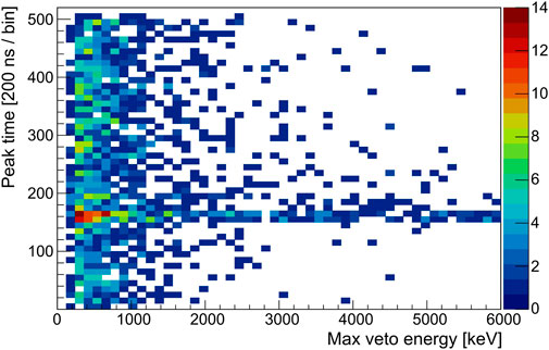
Figure 9. A histogram of the veto signals from background data with their energy and peak time. The excess at peak time bin
After the analysis of the data of the veto system, additional non-muon background can be discriminated. As shown in Section 3, the signature of background induced by cosmic neutrons is expected to be events with a high multiplicity, with the individual signals spread over several tens of microseconds. Additionally, direct neutron interactions in the vetoes or multiple gamma interactions after the capture can result in coincident signals in multiple vetoes. It was found that the following observables facilitate to identify background events:
• Overall multiplicity: number of hit vetoes per event.
• Multiplicity within a time window: the number of veto signals within a fixed time window.
• Sum of energy of veto signals within a time window.
• Minimum peak time difference of the signals in an event: if this value is small or 0, it means that two or more signals came in coincidence.
The parameters for these cuts were optimized using the optimization procedure described above, with independent time windows for each. Histograms of these observables are shown in Figure 10. In general it can be observed that the multiplicity and sum of energies observables show an excess of signals at higher values in the background data.
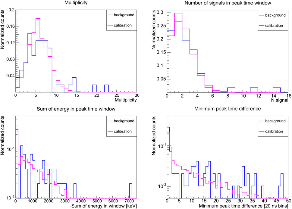
Figure 10. The observables generated from the veto data to discriminate background. The multiplicity (overall and in a reduced time window) and sum of energies have an excess of signals at higher values for the background data. The plot on the lower right shows the minimum time difference between two signals of an event: 0 means that at least two signals are in coincidence, which is more common in the background data.
The background data analyzed in this study was taken during effectively 52.1 days. In this time 1,305,996 raw events were collected in the entire detector and full energy range. By restricting the energy to the ROI of 2–7 keV and discarding events outside the central spot with 9 mm radius, the number of events is reduced by more than 90%. Applying the other selection criteria described in Section 4.2 (also see Figure 8) using only the Micromegas data, 257 background events remain (0.02%). In the calibration data most events pass the cuts at an efficiency of 81.9% in the ROI.
The muon discrimination with the veto system further reduces the number of background events by a factor of 4.6, down to 56 events. Thus the background level4 in the focal spot and ROI is 9.78 × 10⁻⁷ counts keV−1 cm−2 s−1. This value is comparable with previous results reported in [27].
This result is improved further with the advanced filter using the veto system. The best results were obtained with the following conditions: overall multiplicity
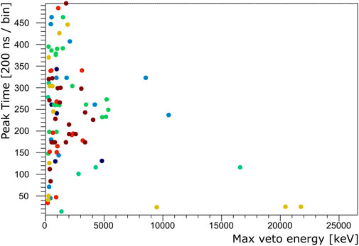
Figure 11. This plot shows the energy and peak time of the veto signals that were identified as background, using the advanced discrimination after the muon cut. The color represents the event, i.e., all points with the same color belong to the same event.
These advanced cuts reduce the number of background events in the central spot and in the ROI by 13%, down to 49 events, while 97% of calibration events are preserved. In summary, and including the statistical error, a background level of
is reached, with an efficiency of 79.4% in the calibration data within the ROI of 2–7 keV. The spectrum of the Micromegas signals before and after the veto cuts is shown in Figure 12.
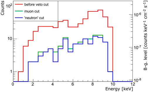
Figure 12. The spectrum of X-ray like events in the Micromegas below 10 keV, before the muon cut (red), after removing muons (green) and after applying the advanced cuts using the veto (blue). On the left axis, the number of counts is shown, while on the right the normalized background level is indicated. The integrated background level is calculated in the range of interest of 2 − 7 keV to avoid the copper X-ray fluorescence peak at 8 keV.
The background level reported here is the lowest ever achieved at above ground level with this type of detector. Comparing the measurements with the simulations presented in the paper, one can see that the measured background rate is at the same level as the simulated neutron-induced background. This indicates that still a large part of this background contribution is not discriminated by the multi-layer veto system. However, it has been shown that looking specifically for events with a neutron-like signature in the vetoes—a high signal multiplicity spread over several tens of microseconds—improves the background level by 13% compared to the one after the muon cut. The veto signals of these additionally rejected events have low energies. Thus we expect that a veto system with a lower energy threshold and a higher segmentation would improve the identification of neutron-induced background events. One has to keep in mind that the current veto was constructed with readily available materials, re-using and adapting several decade-old scintillator panels. An upgrade would be realized with new equipment specifically designed for BabyIAXO.
In general, the goal of the detector development is to reduce the background level even more to 1 × 10⁻⁷ counts keV−1 cm−2 s−1. To achieve this, two new Micromegas prototype setups have been prepared, one at surface level at the University of Zaragoza, the other in the Canfranc underground laboratory (LSC). This setup will help to understand the contributions of cosmic and terrestrial background sources better. In addition, the radiopurity of the components of the new detectors has been improved, and radiopure electronics are in development. Also the calibration capabilities have been enhanced by using custom X-ray generators. The setup at LSC is already in operation, while the other is currently under commissioning. Additionally, the collaboration is working on an improved veto-system.
The raw data supporting the conclusion of this article will be made available by the authors, without undue reservation.
KA: Validation, Writing–review and editing, Writing–original draft, Visualization, Software, Methodology, Investigation, Formal Analysis, Data curation, Conceptualization. JC: Visualization, Validation, Resources, Methodology, Investigation, Writing–review and editing. SG: Validation, Investigation, Funding acquisition, Conceptualization, Writing–review and editing. TD: Validation, Supervision, Methodology, Investigation, Funding acquisition, Conceptualization, Writing–review and editing. DD-I: Software, Methodology, Investigation, Writing–review and editing. AE: Validation, Software, Methodology, Investigation, Writing–review and editing. EF-R: Validation, Supervision, Resources, Project administration, Methodology, Investigation, Conceptualization, Writing–review and editing. JGa: Supervision, Software, Methodology, Investigation, Data curation, Conceptualization, Writing–review and editing. JGi: Resources, Methodology, Investigation, Writing–review and editing. JaG: Validation, Software, Methodology, Investigation, Conceptualization, Writing–review and editing. AG: Investigation, Conceptualization, Writing–review and editing. CG: Conceptualization, Writing–review and editing. II: Supervision, Software, Project administration, Methodology, Investigation, Funding acquisition, Data curation, Conceptualization, Writing–review and editing. CL: Conceptualization, Writing–review and editing. GL: Supervision, Software, Methodology, Investigation, Funding acquisition, Conceptualization, Writing–review and editing. XN: Investigation, Conceptualization, Writing–review and editing. CM: Validation, Software, Methodology, Investigation, Formal Analysis, Data curation, Conceptualization, Writing–review and editing. HM: Validation, Resources, Methodology, Investigation, Writing–review and editing. LO: Visualization, Software, Methodology, Investigation, Formal Analysis, Data curation, Conceptualization, Writing–review and editing, Writing–original draft. AO: Validation, Resources, Methodology, Investigation, Writing–review and editing. TP: Validation, Resources, Methodology, Investigation, Conceptualization, Writing–review and editing. OP: Validation, Software, Investigation, Writing–review and editing. AQ: Validation, Software, Investigation, Writing–review and editing. JR: Validation, Software, Methodology, Investigation, Conceptualization, Writing–review and editing. JV: Validation, Methodology, Investigation, Conceptualization, Writing–review and editing.
The author(s) declare that financial support was received for the research, authorship, and/or publication of this article. We acknowledge support from the European Union’s Horizon 2020 research and innovation programme under the European Research Council (ERC) grant agreement ERC-2017-AdG788781 (IAXO+) and under the Marie Skłodowska-Curie grant agreement No 101026819 (LOBRES); grant PID2019-108122GB-C31 funded by MCIN/AEI/10.13039/501100011033 and funds from “European Union NextGenerationEU/PRTR” (Planes complementarios, Programa de Astrofísica y Física de Altas Energías). We also acknowledge support from the Agence Nationale de la Recherche (France) ANR-19-CE31-133 0024.
This work has been performed as part of the IAXO collaboration. We would like to thank our collaborators, in particular the ones from the IAXO Detector Working Group. We also thank in particular the INR and U. Mainz colleagues for enabling the in-kind contribution consisting of the plastic scintillators used in this work. The authors would like to acknowledge the use of Servicio General de Apoyo a la Investigación-SAI, Universidad de Zaragoza.
The authors declare that the research was conducted in the absence of any commercial or financial relationships that could be construed as a potential conflict of interest.
All claims expressed in this article are solely those of the authors and do not necessarily represent those of their affiliated organizations, or those of the publisher, the editors and the reviewers. Any product that may be evaluated in this article, or claim that may be made by its manufacturer, is not guaranteed or endorsed by the publisher.
1Centro de Astropartículas y Física de Altas Energías, https://capa.unizar.es/en/
2Laboratorio Subterráneo de Canfranc, https://lsc-canfranc.es/en/
3A fixed value of the real veto threshold cannot be given due to a short light attenuation length when compared to the panel length. The threshold of the vetoes is in the order of several hundred keV, as measurements with gamma sources showed, so the threshold of 1 MeV was chosen as a representative value.
4The background level bgl is calculated in the following way from the number of counts Ncounts: bgl = Ncounts/(tmeas. ⋅ adet. ⋅ΔE), where the measurement time tmeas. is 52.1 days, the energy range ΔE is 5 keV and the fiducial detector area adet. is 2.54 cm2.
1. Abeln A, Altenmüller K, Cuendis SA, Armengaud E, Attié D, Aune S, et al. Conceptual design of BabyIAXO, the intermediate stage towards the international axion observatory. JHEP (2021) 2105:137. doi:10.1007/JHEP05(2021)137
2. Armengaud E, Avignone FT, Betz M, Brax P, Brun P, Cantatore G, et al. Conceptual design of the international axion observatory (IAXO). J Instrumentation (2014) 9:T05002. doi:10.1088/1748-0221/9/05/t05002
3. Peccei RD, Quinn HR. CP conservation in the presence of pseudoparticles. Phys Rev Lett (1977) 38:1440–3. doi:10.1103/PhysRevLett.38.1440
4. Peccei RD, Quinn HR. Constraints imposed by CP conservation in the presence of pseudoparticles. Phys Rev D (1977) 16:1791–7. doi:10.1103/PhysRevD.16.1791
5. Redondo J. Solar axion flux from the axion-electron coupling. J Cosmology Astroparticle Phys (2013) 2013:008. doi:10.1088/1475-7516/2013/12/008
6. Hoof S, Jaeckel J, Thormaehlen LJ. Quantifying uncertainties in the solar axion flux and their impact on determining axion model parameters. JCAP (2021) 2021:006. doi:10.1088/1475-7516/2021/09/006
7. Kim JE. Light pseudoscalars, particle physics and cosmology. Phys Rep (1987) 150:1–177. doi:10.1016/0370-1573(87)90017-2
8. Chadha-Day F, Ellis J, Marsh DJE. Axion dark matter: what is it and why now? Sci Adv (2022) 8:eabj3618. doi:10.1126/sciadv.abj3618
9. Isern J, García-Berro E, Torres S, Catalán S. Axions and the cooling of white dwarf stars. Astrophysical J (2008) 682:L109–12. doi:10.1086/591042
10. Di Luzio L, Fedele M, Giannotti M, Mescia F, Nardi E. Stellar evolution confronts axion models. JCAP (2022) 2022:035. doi:10.1088/1475-7516/2022/02/035
11. Meyer M, Horns D, Raue M. First lower limits on the photon-axion-like particle coupling from very high energy gamma-ray observations. Phys Rev D (2013) 87:035027. doi:10.1103/PhysRevD.87.035027
12. Irastorza I, Avignone F, Caspi S, Carmona J, Dafni T, Davenport M, et al. Towards a new generation axion helioscope. J Cosmology Astroparticle Phys (2011) 2011:013. doi:10.1088/1475-7516/2011/06/013
13. Anastassopoulos V. New CAST limit on the axion-photon interaction. Nat Phys (2017) 13:584–90. doi:10.1038/nphys4109
14. Sikivie P. Experimental tests of the “invisible” axion. Phys Rev Lett (1983) 51:1415–7. doi:10.1103/PhysRevLett.51.1415
15. Altenmüller K, Biasuzzi B, Castel J, Cebrián S, Dafni T, Desch K, et al. X-ray detectors for the BabyIAXO solar axion search. Nucl Instr Methods Phys Res Section A: Acc Spectrometers, Detectors Associated Equipment (2023) 1048:167913. doi:10.1016/j.nima.2022.167913
16. Armengaud E, Attié D, Basso S, Brun P, Bykovskiy N, Carmona J, et al. Physics potential of the international axion observatory (IAXO). J Cosmology Astroparticle Phys (2019) 2019:047. doi:10.1088/1475-7516/2019/06/047
17. Tomas A, Aune S, Dafni T, Fanourakis G, Ferrer-Ribas E, Galán J, et al. CAST microbulk micromegas in the canfranc underground laboratory. Phys Proced (2012) 37:478–82. doi:10.1016/j.phpro.2012.02.399
18. Ruiz Chóliz E Ultra-low background micromegas X-ray detectors for axion searches in IAXO and BabyIAXO. Phd thesis. Zaragoza, Spain: Universidad de Zaragoza (2019).
19. Giomataris Y, Rebourgeard P, Robert J, Charpak G. Micromegas: a high-granularity position-sensitive gaseous detector for high particle-flux environments. Nucl Instr Methods Phys Res Section A: Acc Spectrometers, Detectors Associated Equipment (1996) 376:29–35. doi:10.1016/0168-9002(96)00175-1
20. Andriamonje S, Attie D, Berthoumieux E, Calviani M, Colas P, Dafni T, et al. Development and performance of microbulk micromegas detectors. J Instrumentation (2010) 5:P02001. doi:10.1088/1748-0221/5/02/p02001
21. Grabmayr P, Hehl T, Stahl A, Annand J, Owens R. A high-resolution, large acceptance scintillation time-of-flight spectrometer. Nucl Instr Methods Phys Res Section A: Acc Spectrometers, Detectors Associated Equipment (1998) 402:85–94. doi:10.1016/S0168-9002(97)01068-1
22. Anvar S, Baron P, Blank B, Chavas J, Delagnes E, Druillole F, et al. AGET, the GET front-end ASIC, for the readout of the time projection chambers used in nuclear physic experiments. In: 2011 IEEE nuclear science symposium conference record (2011). p. 745–9. doi:10.1109/NSSMIC.2011.6154095
23. Allison J, Amako K, Apostolakis J, Arce P, Asai M, Aso T, et al. Recent developments in Geant4. Nucl Instr Methods Phys Res Section A: Acc Spectrometers, Detectors Associated Equipment (2016) 835:186–225. doi:10.1016/j.nima.2016.06.125
24. Altenmüller K, Cebrián S, Dafni T, Díez-Ibáñez D, Galán J, Galindo J, et al. REST-for-Physics, a ROOT-based framework for event oriented data analysis and combined Monte Carlo response. Comp Phys Commun (2022) 273:108281. doi:10.1016/j.cpc.2021.108281
25. Gordon M, Goldhagen P, Rodbell K, Zabel T, Tang H, Clem J, et al. Measurement of the flux and energy spectrum of cosmic-ray induced neutrons on the ground. IEEE Trans Nucl Sci (2004) 51:3427–34. doi:10.1109/TNS.2004.839134
26. Schindler H, Veenhof R. Garfield++ — simulation of ionisation based tracking detectors (2024). Available from: http://garfieldpp.web.cern.ch/garfieldpp (Accessed April 02, 2024).
Keywords: axions, rare event search, TPC (time projection chamber), background discrimination, x-ray detector, ultra low background, gaseous detector, micro pattern detector
Citation: Altenmüller K, Castel JF, Cebrián S, Dafni T, Díez-Ibañez D, Ezquerro A, Ferrer-Ribas E, Galan J, Galindo J, García JA, Giganon A, Goblin C, Irastorza IG, Loiseau C, Luzón G, Navick XF, Margalejo C, Mirallas H, Obis L, Ortiz de Solórzano A, Papaevangelou T, Pérez O, Quintana A, Ruz J and Vogel JK (2024) Background discrimination with a Micromegas detector prototype and veto system for BabyIAXO. Front. Phys. 12:1384415. doi: 10.3389/fphy.2024.1384415
Received: 09 February 2024; Accepted: 22 April 2024;
Published: 23 May 2024.
Edited by:
Bhupal Dev, Washington University in St. Louis, United StatesReviewed by:
Stanislav Pospíšil, Czech Technical University in Prague, CzechiaCopyright © 2024 Altenmüller, Castel, Cebrián, Dafni, Díez-Ibañez, Ezquerro, Ferrer-Ribas, Galan, Galindo, García, Giganon, Goblin, Irastorza, Loiseau, Luzón, Navick, Margalejo, Mirallas, Obis, Ortiz de Solórzano, Papaevangelou, Pérez, Quintana, Ruz and Vogel. This is an open-access article distributed under the terms of the Creative Commons Attribution License (CC BY). The use, distribution or reproduction in other forums is permitted, provided the original author(s) and the copyright owner(s) are credited and that the original publication in this journal is cited, in accordance with accepted academic practice. No use, distribution or reproduction is permitted which does not comply with these terms.
*Correspondence: K. Altenmüller, a29ucmFkLmFsdGVubXVlbGxlckB1bml6YXIuZXM=
Disclaimer: All claims expressed in this article are solely those of the authors and do not necessarily represent those of their affiliated organizations, or those of the publisher, the editors and the reviewers. Any product that may be evaluated in this article or claim that may be made by its manufacturer is not guaranteed or endorsed by the publisher.
Research integrity at Frontiers
Learn more about the work of our research integrity team to safeguard the quality of each article we publish.