- 1College of Architecture and Civil Engineering, Xinyang Normal University, Xinyang, China
- 2Henan New Environmentally-Friendly Civil Engineering Materials Engineering Research Center, Xinyang Normal University, Xinyang, China
- 3Henan International Joint Laboratory of Structural Mechanics and Computational Simulation, Huanghuai University, Zhumadian, China
As an environmentally friendly alternative to ordinary concrete, slag concrete is subject to limitations such as drying shrinkage and micro-cracking during its promotion and application. In order to address these challenges, steel fibers, known for their excellent tensile, shear, crack-resistance, and toughness properties, have been introduced to enhance the ductility of alkali-activated slag concrete. This study utilized steel fiber content as a variable and produced eight steel fiber-reinforced alkali-activated slag concrete beams to investigate their flexural mechanical properties. By exploring the influence of steel fiber content variation on the mechanical behavior of alkali-activated slag concrete beams and conducting validation through finite element analysis, the study unveiled the impact of steel fibers on the performance of alkali-activated slag concrete beams. The research findings demonstrate a significant enhancement in the flexural mechanical properties of alkali-activated slag concrete beams with the addition of steel fibers, leading to a reduction in surface cracking and an improvement in the durability of the elements. The outcomes of this study hold crucial theoretical implications for the widespread application of steel fiber-reinforced alkali-activated slag concrete.
1 Introduction
Resource scarcity and environmental pollution have always been prominent concerns in contemporary human society. As a crucial component in the construction process, cement is manufactured and consumed on a substantial scale annually. Traditional cement production, employing the “two grinding and one burning” process, not only depletes considerable energy resources but also generates significant quantities of harmful gases like NOx, SO2, and greenhouse gases like CO2 during clinker calcination, thereby exerting a severe impact on the natural environment [1–3]. According to statistical data provided in 2022 by China’s Ministry of Ecology and Environment, the cement industry’s emissions of particulate matter and nitrogen oxides account for 20.9% and 17.3% of the total industrial emissions in the country, respectively, while CO2 emissions constitute approximately 13.0% of the overall national emissions, resulting in substantial environmental consequences. Consequently, the adoption of novel and eco-friendly structural materials as substitutes for conventional concrete is imperative [4, 5]. Therefore, the development of innovative and sustainable construction materials is not only a leading trend in the field of civil engineering materials but also a critical objective within the current global resource and energy development strategies.
In recent years, alkali-activated slag concrete has emerged as an environmentally-friendly substitute for ordinary Portland cement (OPC) concrete [6–8]. As a novel, energy-efficient, and eco-friendly building material, alkali-activated slag cement maximizes the utilization of industrial waste and by-products, such as fly ash and granulated blast furnace slag, thus achieving optimal secondary utilization of industrial waste. In comparison to ordinary Portland cement, alkali-activated slag cement significantly reduces the energy consumption and environmental pollution associated with raw material production [9, 10]. The raw material production process of alkali-activated slag concrete is straightforward, characterized by low energy consumption and high utilization of industrial solid waste. Relative to ordinary Portland cement concrete, alkali-activated slag concrete demonstrates excellent mechanical and durability properties, including high strength, freeze-thaw resistance, and corrosion resistance [11].
However, alkali-activated slag concrete does have certain drawbacks that limit its widespread adoption and application. These include its sensitivity to environmental factors, short setting time [12], high carbonation rate, and susceptibility to steel bar corrosion [13]. It is also prone to potential alkali-aggregate reaction [14], shrinkage, and the formation of micro-cracks due to significant drying shrinkage [15, 16]. These issues have a significant impact on the promotion and application of alkali-activated slag concrete. The occurrence of micro-cracks caused by drying shrinkage can gradually worsen over time, leading to the corrosion of internal steel bars. This ultimately affects the durability and safety of structural components [17]. Durability is a critical functional requirement for building structures. Therefore, effectively addressing the excessive formation of micro-cracks resulting from the drying shrinkage of alkali-activated slag concrete is crucial for improving the material’s durability during use.
Steel fibers, as the most common fiber material, possess excellent tensile, shear, crack resistance, and toughness properties. The addition of steel fibers in concrete matrix materials can enhance the concrete’s resistance to permeability, shrinkage, and deformation, as well as reduce the width of cracks during normal structural usage [18]. Therefore, it is possible to incorporate steel fibers into alkali-activated slag concrete to mitigate its drying shrinkage behavior and improve post-cracking behavior, toughness, and ductility [19, 20]. Relevant studies have been conducted in this regard. For instance, Qin et al. [21] found that steel fibers enhance the toughness of alkali-activated slag concrete. However, excessive steel fibers tend to aggregate and do not distribute uniformly in the concrete, leading to increased internal defects. Serdar et al. [22] investigated the influence of steel fiber content and length on the properties of alkali-activated slag mortar. The results showed that with increasing steel fiber content and length, the drying shrinkage decreases gradually, while the compressive and flexural strengths increase. Gülsßan [23] studied the influence of nano-silica and steel fibers on the workability and mechanical performance of self-consolidating geopolymer concrete. The findings suggested that the incorporation of nano-silica and steel fibers negatively affects workability but significantly improves the flexural performance of geopolymer concrete.
Steel fiber alkali-activated slag concrete demonstrates potential applications in the construction industry similar to those of standard Portland cement concrete. However, a comprehensive evaluation of its mechanical and load-bearing performance in structural components necessitates extensive component testing and adherence to applicable regulations. Regrettably, the existing literature on the use of steel fiber alkali-activated slag concrete in structural components is limited, requiring further research to provide theoretical references for its application and promotion. Therefore, the objective of this study is to investigate the flexural mechanical properties of steel fiber alkali-activated slag concrete beams by varying the steel fiber content. This research endeavor will explore the influence of different steel fiber contents on the mechanical performance of steel fiber alkali-activated slag concrete beams and validate these findings through finite element analysis.
2 Experimental
2.1 Materials
Milled steel fibers were selected for use, with a length (Lf) of 36 mm, a width of 2.3 mm, and a thickness of 0.6 mm. The effective diameter df is 1.08 mm, and the length-to-diameter ratio (Lf/df) is 27.07. The tensile strength is 700 MPa.
The slag is sourced from Xinxing Cement Plant in Henan Province, China. According to the standard “Ground granulated blast furnace slag powder for use in cement and concrete” (GB/T 18046-2000), its physical properties were tested and it was classified as an S95 grade. The density of the slag was determined to be 3.27 g/cm3 and the specific surface area was calculated to be 434.6 m2/kg. Scanning electron microscopy revealed that the slag particles were irregularly shaped blocks.
The fly ash is sourced from Yangluo Power Plant in Wuhan, China. According to the standard “Fly ash for use in cement and concrete” (GB/T 1596-2005), its physical properties were tested. The density of the fly ash was determined to be 2.187 g/cm3. Scanning electron microscopy revealed that the fly ash particles were spherical in shape with a regular structure.
The activator solution is a mixture of sodium hydroxide, water glass (sodium silicate), and water, with a mass ratio of 100 kg/m3: 10.36 kg/m3: 90.35 kg/m3. The modulus of the water glass in the solution was determined to be 2.93 using the titration method. The role of sodium hydroxide is to adjust the modulus of the water glass, which was subsequently adjusted to 1.6. Water, on the other hand, is used to regulate the moisture content of the activator solution, resulting in a final moisture content of 73.5%.
The fine aggregate is sourced from the Xinxiang River in China. Its physical properties were tested according to “Standard for Quality and Testing of Sand and Stone for Ordinary Concrete” (JGJ 52-2006). The apparent density of the sand was determined to be 2,600 kg/m3, and the fineness modulus was found to be 2.99, belonging to Zone II medium sand.
The coarse aggregate is sourced from the Xinxiang quarry in China, with a particle size less than 20 mm. Its physical properties were tested according to the standard “Standard for Quality and Testing of Sand and Stone for Ordinary Concrete” (JGJ 52-2006). The apparent density of the stone was determined to be 2,700 kg/m3.
2.2 Test beams
A total of 8 steel fiber reinforced alkali-activated slag concrete (SFRASC) beams were produced, with steel fiber dosages (Vf) of 0.0%, 0.5%, 0.9%, 1.0%, 1.1%, 1.2%, 1.3%, and 1.4%, respectively. The test specimens were numbered SFRASC-X (1-8). The cross-sectional dimensions of the test beams were 120 mm × 200 mm, and the beam length was 2000 mm. The bottom reinforcement was  with a cross-sectional area of 402 mm2 and a reinforcement ratio of 2.0%. The formwork was supported by
  stirrups and tied with
  hoop steel. The thickness of the protective layer was 25 cm, and the shear-to-span ratio of the beam was 3.6. The beams’ reinforcement diagram is shown in Figure 1. The concrete mix ratio of the test beam is shown in Table 1.
2.3 Measuring point layout
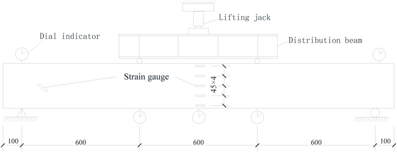
The displacement was measured using a dial gauge, with a total of 5 displacement measurement points placed at the beams’ support top surface, mid-span (L/2), and mid-span (L/3), respectively. The theoretical value of the mid-span displacement was calculated as the difference between the measured mid-span displacement and the average displacement measured at the supports. Strain gauges of type BE120-5AA were placed on the surface of the bottom reinforcing steel bars, while strain gauges of type BX120-50AA were placed on the surface of the positive cross-sectional side at the mid-span of the beam, with a spacing of 45 mm. The bottom-most strain gauge was situated 10 mm away from the bottom of the beam, and the topmost strain gauge was positioned 10 mm away from the top of the beam. Strain gauges were also placed on the concrete surface in the neutral axis of the support’s shear web, aligned in the direction of tensile stress trace, as per the layout indicated in the test specimen arrangement diagram shown in Figure 2. Cracks were tested in the pure bending section and the bending-shear zone using a reading microscope of type MG10085-1.
2.4 Test standards
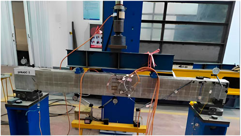
The test was conducted in accordance with the relevant provisions of the “Standard Test Methods for Concrete Structures” (GB/T 50152-2012). Preloading: the specimen was preloaded to 5 kN and then unloaded to 0 kN, repeated twice. Formal loading: the loading was carried out in a stepwise manner, with each load level set at 5 kN. After the completion of each loading stage, the load was held for approximately 5 min, during which data were recorded, and the surface cracks on the beam were marked using a marker pen. As the cracking load value approached, the load increment for each stage was reduced to 1 kN to ensure accurate measurement of the cracking load. Once the specimen cracked, the load for each stage was readjusted to 5 kN. The test was concluded when the measured deflection of the beam reached L/50 of the span, indicating the beam had reached its ultimate bearing capacity limit state. Experimental loading device diagram of the beams’ is shown in Figure 3.
3 Results and discussion
3.1 Load results and analysis
The results of the tests for the normal section cracking load (Pcr), mid span cracking moment (Mfcr0), diagonal section cracking load (P’cr), diagonal section cracking shear force (Vcr), ultimate load (Pu), ultimate moment (Mfu0) are presented in Table 2. As shown in the experimental results in Table 2, the addition of steel fibers significantly enhances the load-carrying capacity of the concrete beams. The function of steel fibers in steel fiber-reinforced concrete is to effectively improve the mechanical and durability properties of the concrete by utilizing their high strength and toughness [24]. The addition of steel fibers effectively enhances the tensile stress and crack resistance of the concrete, thereby preventing cracking and fracture [25, 26], and consequently improving the overall flexural performance and load-bearing capacity of steel fiber reinforced alkali-activated slag concrete beams.
The theoretical value of the positive section bending load-bearing capacity of the test beam was calculated according to the formula specified in the “Technical Code for Fiber Reinforced Concrete Structures” (CECS38:2004). The comparison between the theoretical calculation and the test result is shown in Figure 4. From the figure, it is evident that the test results exhibit a reasonable level of agreement with the theoretical calculations. The theoretical calculation curve appears to be smoother in comparison, whereas the test curve shows some fluctuations. These variations can be attributed to multiple factors, including test conditions, the testing process, and the characteristics of the test specimens themselves. The ratio of the average test value to the average calculated value is found to be 1.0218, with a standard deviation of 0.0106 and a coefficient of variation of 0.0104. These results indicate that the calculation formula for determining the positive section bearing capacity of the beam, as specified in the guidelines, is equally applicable to steel fiber alkali slag concrete beams. These values suggest a relatively small deviation from the theoretical calculations, further supporting the reliability and suitability of the formula for this type of concrete beam.
3.2 Deflection results and analysis
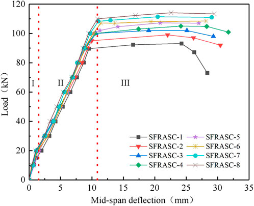
The load-deflection curves for the tested beams are presented in Figure 5. The load-deflection curve can be divided into three stages. In Stage I, there is a linear relationship between load and deflection. In Stage II, cracking occurs in the beam, causing the load to transfer abruptly from the concrete to the reinforcing steel bars. This results in a decrease in effective height, stiffness, and an increase in the rate of deflection. A clear inflection point can be observed between Stage I and Stage II. Finally, in Stage III, the load remains constant, but the displacement increases rapidly as the beam reaches its ultimate limit state.
Analysis of the eight load-deflection curves reveals that the difference in stiffness among the beams in Stage I is not significant. In Stage II, it is noticeable that the increase in deflection rate for beams containing steel fibers is lower than that for the non-fiber reinforced specimens. This suggests that the addition of steel fibers contributes to the ductility of steel fiber alkali slag concrete beams. For instance, at a load of 60kN, the mid-span deflection of the SFRASC-1, SFRASC-2, SFRASC-4, and SFRASC-8 beams were 6.57 mm, 6.21 mm, 6.1 mm, and 5.41 mm, respectively.
Moreover, as the steel fiber content increases, the load capacity gradually increases. For steel fiber content below 1.1%, the deflection curve of the test specimen experiences a horizontal development phase followed by a drop. For steel fiber content greater than 1.1%, the deflection curve is without a downward phase. This provides further evidence of the positive impact of steel fibers on the ductility of steel fiber alkali slag concrete beams.
Overall, the results highlight the potential of steel fibers to enhance the mechanical and structural properties of concrete. The findings also have significant implications for the design and construction of durable infrastructure.
3.3 Crack results and analysis
Figure 6 illustrates the expansion of surface cracks on the lateral side of eight tested beams. The numerical values in the figure correspond to the load conditions at which cracks become noticeable. Observing the figure, it can be seen that once the load reaches the cracking load for the normal section, an initial vertical crack manifests in the middle of the beam span within the normal section. Subsequently, as the load further increases, the vertical crack progressively extends upward while simultaneously widening.
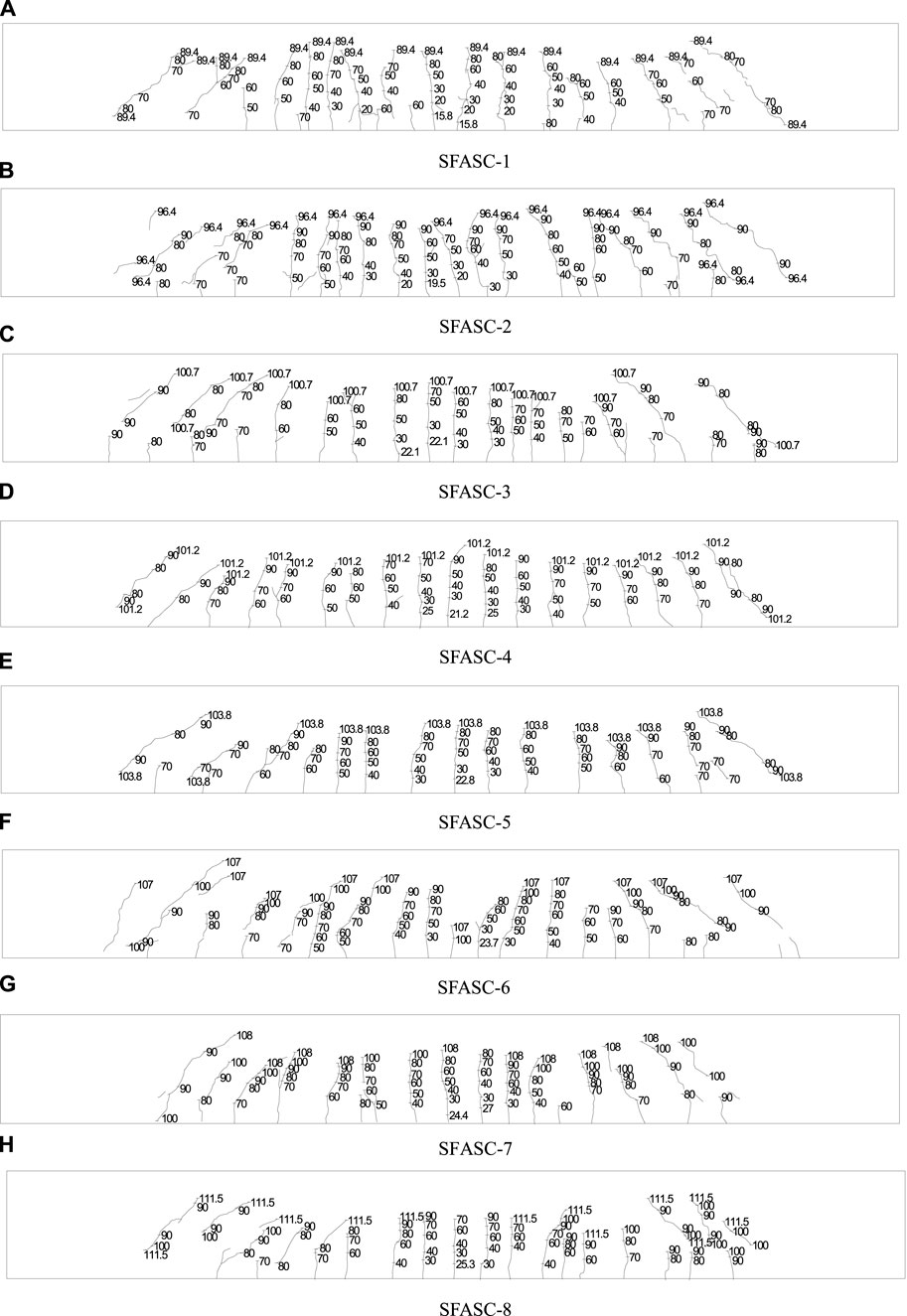
FIGURE 6. Development and distribution of surface cracks during the bending process of SFRASC-1, SFRASC-2, SFRASC-3, SFRASC-4, SFRASC-5, SFRASC-7, and SFRASC-8.
Upon reaching the cracking load for the diagonal section, diagonal cracks emerge in a 45° direction from the neutral axis of the beam’s support region. As the load continues to rise, these diagonal cracks gradually propagate towards both the support and loading positions. As the beam approaches failure, the load stabilizes, yet the crack width experiences a rapid expansion.
Analysis of the surface crack distribution reveals that an increase in steel fiber content leads to a significant reduction in beam surface cracks. This positive outcome can be primarily attributed to the beneficial effects of steel fibers, including crack bridging and improved crack resistance [27, 28].
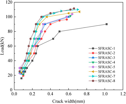
As the bending process of the test beam progresses, the increase in the number of surface cracks corresponds to a continuous increase in both the width and height of each crack. The magnitude of crack width stands out as a pivotal factor influencing the load-bearing capacity of the test beam. During the bending test, cracks predominantly manifest in the pure bending section, particularly in the lower extremity where tensile stress reaches its peak. Consequently, the maximum crack width is chiefly observed in the pure bending section, a phenomenon that becomes particularly conspicuous during the bending failure of a concrete beam. The load versus maximum crack width relationship of the test beam is portrayed in Figure 7 based on the test findings.
Figure 7 illustrates that the inclusion of steel fibers in the test beam delayed cracking and substantially reduced the maximum crack width under equivalent loads. Initially, when the test beam undergoes cracking, the longitudinal tensile steel bars remain unyielding. At this stage, the crack development is constrained not only by the bond strength between the ribbed longitudinal bars and the concrete, but also by the interaction of steel fibers with the concrete on either side of the crack. The subsequent increase in maximum crack width is considerably slower. For instance, at a load of 40 kN, test beams with steel fiber contents of 0% and 1.0% exhibited maximum crack widths of 0.20 mm and 0.16 mm, respectively, marking a 20% reduction. Additionally, the tensile longitudinal reinforcement’s effectiveness in restraining crack propagation diminishes drastically in alkali slag concrete beams upon yielding, leading to a notable surge in maximum crack width for SFASC1 beams. However, steel fiber alkali slag concrete beams demonstrate a bridging effect at crack sites, impeding crack propagation and resulting in a slower increase in maximum crack width after tensile longitudinal reinforcement yield. At a load of 80 kN, test beams with steel fiber contents of 0% and 1.0% displayed maximum crack widths of 0.50 mm and 0.30 mm, respectively, representing a 40% reduction.
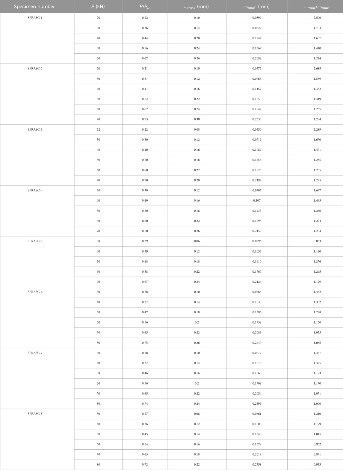
In accordance with the theoretical calculation method for determining the maximum crack width of beams outlined in the Technical Specification for Fiber Reinforced Concrete Structures (CECS38:2004), the maximum crack widths for each test beam under various load levels were computed. The resulting theoretical and experimental values are presented in Table 3 for comparative analysis. Where the P is the load of the test, ωfmax and ωfmaxc is experimental and theoretical values of crack width respective.
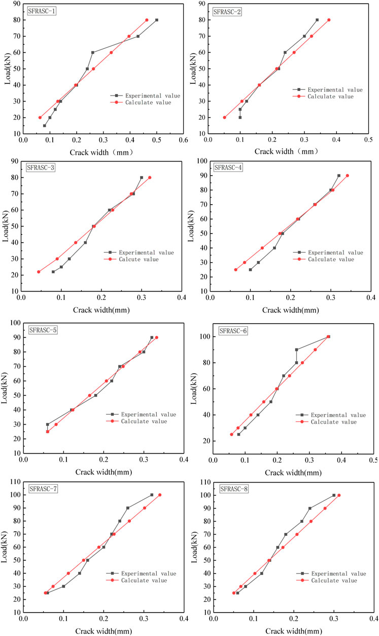
Based on the results presented in Table 3, certain disparities exist between the experimental values and the theoretical calculations, primarily due to the influence of steel fiber content on crack width. To account for this effect, the formula for computing the maximum crack width, as specified in the guidelines, is revised with the incorporation of the steel fiber crack reduction coefficient γ. The modified formula is shown as Eq. 1.
In the revised formula, the symbol ωfmax represents the maximum crack width of the fiber-reinforced concrete beams, while ωmax refers to the corresponding calculation formulas provided in the “Code for Design of Concrete Structures” (GB50010-2010). Additionally, λf denotes the characteristic parameters of steel fibers, and βcw represents the coefficient that accounts for the influence of steel fibers on the crack width of structural components. Specifically, for bending components, the value of βcw is set to 0.35. Linear regression is employed to compute the average ratio between the experimental value and the calculated value of the steel fiber crack reduction coefficient γ. The calculation formula is shown as Eq. 2.
Figure 8 displays the comparison curve between the computed results obtained from the modified formula and the experimental data. The figure reveals a high level of concordance between the calculated outcomes and the empirical values, signifying the potential theoretical relevance of these calculations in real-world engineering scenarios.
3.4 Strain results and analysis
The surface strain analysis conducted on the lateral side of the beam demonstrates that the cross-section of the beam adheres to the assumption of having a flat section throughout the stress process. This study exclusively presents the surface strain test results for specimens with 0% and 1% steel fiber content. Figure 9 exhibits the surface strain distribution along the height of the beam cross-section on the normal section side of the specimen. The cracking load of the two test beams is observed to manifest at distances of 6.7 mm and 14.1 mm above the beam’s centerline, respectively. The inclusion of steel fibers enhances the tensile strength of alkali slag concrete. By virtue of the static equilibrium principle, beams containing steel fibers exhibit a relatively diminished height for the relative compression zone. This experimental finding aligns with theoretical expectations. With an incremental increase in the applied load, the position of the neutral axis progressively shifts upwards, and the strain on the lateral surface of the beam exhibits a linear descent along the beam’s height.
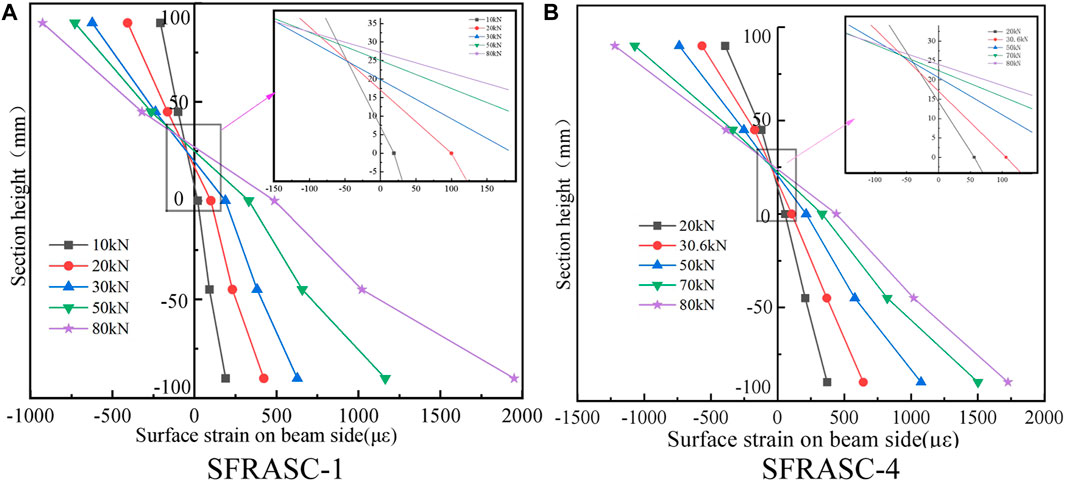
FIGURE 9. Surface strain distribution along the height of the beam cross-section of SFRASC-1 and SFRASC-4.
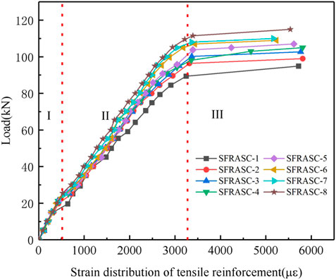
Figure 10 illustrates the relationship between the strain of the longitudinal steel bars at the bottom of the test beam and the applied load. It can be categorized into three distinct stages, analogous to the load-deflection curve. In Stage I, which corresponds to low load levels, a linear relationship between strain and load is observed, indicating the specimen’s elastic behavior. Stage II marks the second phase, wherein a clear inflection point manifests at the intersection of Stages I and II. This inflection point signifies the onset of concrete cracking, resulting in the instantaneous transfer of tension from the beam’s bottom to the longitudinal steel bars and a redistribution of stress within the beam section. The inclusion of steel fibers mitigates the inflection point phenomenon in specimens, leading to a gradual increase in the strain of the longitudinal steel bars with subsequent load increments. Stage III designates the third phase, where the load reaches its ultimate capacity and remains constant, while the strain of the longitudinal steel bars continues to increase. It is evident from the curve that specimens with added steel fibers exhibit comparatively lower strains in the longitudinal steel bars under the same applied load. Furthermore, the ultimate load of the specimens progressively increases with higher steel fiber content, corroborating the earlier analyzed findings.
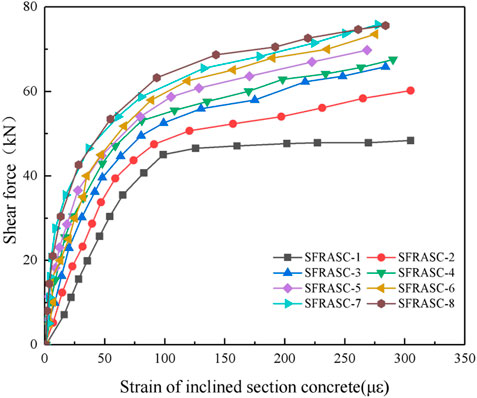
Figure 11 displays the relationship curve between the principal tensile strain and load at the oblique section of each specimen. Prior to the occurrence of diagonal section cracking, the concrete and reinforcement primarily bear the shear force in the oblique section. Subsequently, as the main tensile stress in the diagonal section reaches the concrete cracking stress, the shear stress gradually transfers to the reinforcement. It is evident from the figure that the specimen with added steel fibers exhibits lower main tensile strain values compared to the specimen without steel fibers, under the same level of load. Furthermore, as the steel fiber content increases, the test values decrease, indicating that the inclusion of steel fibers enhances the tensile strength of alkali slag concrete. The steel fibers assist in sharing some of the tensile force of the concrete, and this effect becomes more pronounced with higher steel fiber content.
4 Analysis of fractal characteristics of SFRASC beams
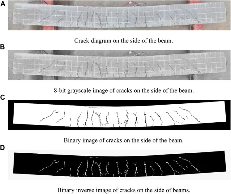
MATLAB is employed for numerical calculations and analysis and fractal theory is applied to describe the intricate distribution of surface cracks on experimental beams. Initially, the RGB crack image of the experimental beam is transformed into an 8-bit grayscale image utilizing MATLAB. Subsequently, a binary image is generated from the grayscale image by applying a threshold where crack pixels are denoted as 0. The binary image is inverted, changing all crack pixels to 1, for subsequent data processing and calculation of the fractal dimension. The adjustment of the coverage network’s grid size “r” is managed by modifying the pixel matrix and sub-matrix of the crack image. For each sub-matrix, the sum of its elements is computed and compared to a threshold of 1 in order to identify non-empty regions, i.e., cracks. This process is repeated for various grid densities to determine the count of non-empty regions at different resolutions. These non-empty regions are termed “boxes” and their sizes are correlated with the fractal dimension. The logarithm of the box size and its corresponding number of boxes N(r) are plotted on a logarithmic coordinate graph. Using the least squares method, a logarithmic relationship curve lnN(r)–ln(r) is derived to describe the change in resolution, where the slope of the curve represents the fractal dimension.
Using specimen SFRASC-1 as a case study, the specific processing procedure is outlined as follows: Firstly, the surface image of the beam is subjected to preprocessing, aiming to eliminate any irrelevant information and focus solely on the test beam, as depicted in Figure 12A. Subsequently, the preprocessed crack image is converted into an 8-bit grayscale image, as displayed in Figure 12B. Binary processing is then applied to the grayscale image, wherein the crack regions are represented in black while the beam surface appears in white, resulting in the binary representation of the crack image shown in Figure 12C. To obtain the inverse crack image, an inverse operation is performed on the binary image, setting the color of the cracks as white and the beam surface as black, as illustrated in Figure 12D.
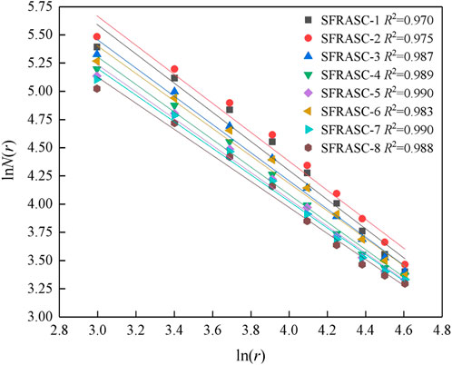
Moreover, the binary image of the inverted crack is divided into different network sizes, namely 20 mm, 30 mm, 40 mm, 50 mm, 60 mm, 70 mm, 80 mm, 90 mm, and 100 mm. By overlaying the crack image, the number of non-empty grids N(r) is determined within each network size for subsequent analysis.
For each group, obtain the logarithm of the box sizes r and the corresponding number of non-empty grids N(r), and fit the lnN(r)—ln(r) relationship curve using the least squares method. The slope of the fitted curve represents the fractal dimension. The fractal dimension of cracks in the test beam under ultimate limit state Fitting results are shown in Figure 13, the correlation coefficient is above 0.9, and the fitting effect is good. The calculation results dimension of different cross-sections during the failure of experimental beams is shown in Table 4.

TABLE 4. Calculation results of the dimension of different cross-sections during the failure of experimental beams.
Upon examination of Table 4, it is evident that there exists a certain degree of variation in the fractal dimension of the pure bending section, bending shear section, and full section across different test beams. This variability indicates distinct differences in crack morphology and distribution among the various test beams. In accordance with fractal theory, smaller fractal dimensions signify more uniform and densely concentrated crack distributions, while larger fractal dimensions indicate more irregular and isolated crack distributions [29]. The larger fractal dimension of the bending shear section for each specimen in the table, in comparison to that of the pure bending section, suggests that the crack distribution in the bending shear section exhibits greater irregularity than that in the pure bending section. This discrepancy can be attributed primarily to the fact that cracks in the pure bending section are predominantly induced by tensile stress in the direction perpendicular to the crack, with parallel shear stress being almost negligible, thereby precluding the occurrence of shear cracks. In contrast, the bending shear section experiences both bending normal stress and shear stress, resulting in a more intricate interplay and contributing to irregularities in crack formation.
In the pure bending and bending shear sections, the fractal dimension gradually decreases with the increase in steel fiber content. This phenomenon indicates that the inclusion of steel fibers exerts a certain retarding effect on the propagation of pure bending cracks and abdominal shear diagonal cracks, resulting in a more uniform and closely distributed crack pattern. This can be mainly attributed to the ability of steel fibers to impede crack expansion and enhance the material’s toughness. Furthermore, the fractal dimension of the entire section also decreases with the rise in steel fiber content, underscoring the positive impact of steel fiber addition in enhancing the crack morphology of the entire section, thereby leading to a more uniform and closely distributed crack pattern.
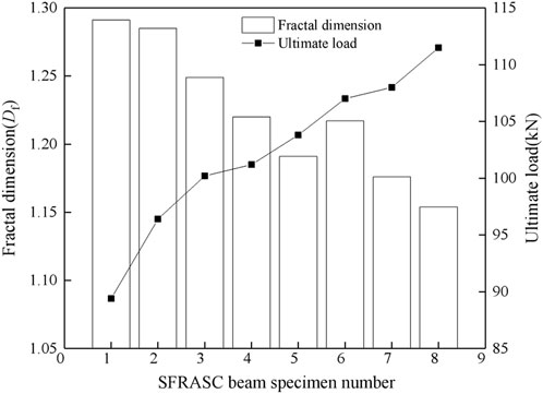
The fractal dimension of each test beam in the limit state is illustrated in Figure 14. As observed in the figure, the fractal dimension of the cracks in the test beam decreases with an increase in steel fiber content. For instance, the fractal dimension of the cracks in SFASC1 alkali slag concrete measures 1.291, while in the test beam with a steel fiber content of 1.4%, it measures 1.154, indicating a reduction of 10.6%. This implies that the addition of steel fibers effectively mitigates crack occurrence, curbs crack propagation, and enhances the load-bearing capacity of the test beam.
5 Numerical simulation analysis
5.1 Finite element model
The numerical analysis was conducted using ABQUS software. The finite element model of the beam was created with dimensions consistent with the experimental beam, employing C3D8R elements for concrete and T3D2 elements for steel reinforcement. To ensure the calculation results were not influenced by the cushion block, a support pad measuring 120 mm × 50 mm × 50 mm was utilized, with the material properties of the cushion block set as rigid. The finite element model of the beam and the reinforcement bar cage is shown in Figure 15.
The constitutive relationship model of concrete material adopts a two-stage damage constitutive model [30–32], which takes into account the progressive degradation of the material as it undergoes loading and damage. Meanwhile, the reinforcement bars adopt a two-stage double line model, which is a common model used to simulate the behavior of steel subjected to tension and compression. This model accounts for the yielding and hardening of the material under different loading conditions. The interface between steel bars and concrete is assumed to have no relative slip, and a composite model [33–35] is adopted.
5.2 Numeric simulation results and analysis
Table 5 presents a comparative analysis of the numerical simulation results and experimental results for the four selected experimental beams. As shown in the table, the cracking load error ranges from 8.7% to 14.5%, and the ultimate load error ranges from 7.4% to 11.1%. These errors stem from the idealized nature of the finite element simulation. In the simulation, the steel fibers are assumed to be uniformly distributed in the test beam, and the concrete material is tightly bonded with isotropic properties. Additionally, a rigid connection is assumed between the concrete and the steel reinforcement skeleton without any relative slip. However, in real-world scenarios, the uniform distribution of steel fibers in concrete beams is challenging to achieve, resulting in non-uniform weak surfaces. Moreover, concrete materials are subject to various factors such as mixing time, methods, and curing techniques, which often lead to the presence of internal microcracks and pores. These differences between the actual conditions and the simulation contribute to the simulated values being greater than the corresponding experimental values.
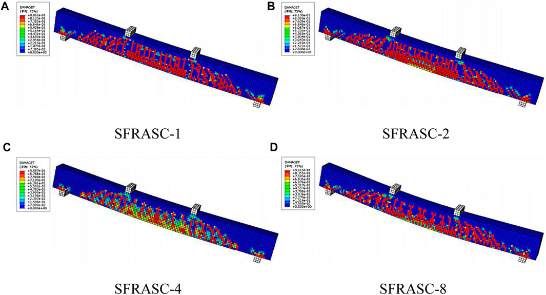
Figure 16 shows the damage cloud map of the simulated test beam at ultimate failure under ultimate load, and it can be seen from the figure that the crack distribution pattern is similar to the test results.
6 Conclusion
Adding steel fibers to alkali-activated slag concrete can enhance the tensile stress and crack resistance of the concrete, thereby improving the flexural performance and load-carrying capacity of alkali-activated slag concrete beams. Within the specified range of steel fiber content in this study, an increasing trend is observed in the effectiveness of these enhancements with the increase of steel fiber content.
The existing “Technical Specification for Fiber Concrete Structures” (CECS38: 2004) regarding the calculation formula of beam cross-sectional load-carrying capacity is also applicable to steel fiber-reinforced alkali-activated slag concrete beams.
Both the experimental and fractal analysis results demonstrate the bridging and crack-arresting effect of steel fibers. The addition of steel fibers significantly reduces the number of surface cracks in beams, with this effect becoming more pronounced as the fiber content increases. The given calculation formula for the maximum crack width of fiber concrete beams in the “Technical Specification for Fiber Concrete Structures” (CECS38: 2004) has been modified, and the results from the adjusted formula correspond well with experimental findings.
The numerical simulation results of the loading closely match the experimental results. The distribution of surface cracks in the numerically simulated beam failure is similar to the experimental results.
Data availability statement
The original contributions presented in the study are included in the article/Supplementary material, further inquiries can be directed to the corresponding author.
Author contributions
XY: Writing–original draft, Writing–review and editing. RH: Writing–review and editing. XZ: Writing–review and editing.
Funding
The author(s) declare that no financial support was received for the research, authorship, and/or publication of this article.
Conflict of interest
The authors declare that the research was conducted in the absence of any commercial or financial relationships that could be construed as a potential conflict of interest.
Publisher’s note
All claims expressed in this article are solely those of the authors and do not necessarily represent those of their affiliated organizations, or those of the publisher, the editors and the reviewers. Any product that may be evaluated in this article, or claim that may be made by its manufacturer, is not guaranteed or endorsed by the publisher.
References
1. Zhao HT, Liu Y, Li XQ, Hao LW. Research progress on low-carbon technologies and assessment methods in cement industry. Mater Sci Forum (2021) 1035:933–43. doi:10.4028/www.scientific.net/msf.1035.933
2. Kumar A, Lakhani R, Mishra R, Khan RK, Khan S. Utilization of solid waste in the production of autoclaved aerated concrete and their effects on its physio-mechanical and microstructural properties: alternative sources, characterization, and performance insights. Int J Concrete Structures Mater (2023) 17(1):6. doi:10.1186/s40069-022-00569-x
3. Guo YY, Luo L, Liu TT, Hao LW, Li YM, Liu PF, et al. A review of low-carbon technologies and projects for the global cement industry. J Environ Sci (China) (2023) 136:682–97. doi:10.1016/j.jes.2023.01.021
4. Saha S, Rajasekaran C. Strength and shrinkage properties of heat-cured fly ash-based geopolymer mortars containing fine recycled concrete aggregate. J Test Eval (2020) 48(6):20180799. doi:10.1520/jte20180799
5. Öztürk ZB, Çam T. Performance of eco-friendly fly ash-based geopolymer mortars with stone-cutting waste. Mater Chem Phys (2023) 307:128112. doi:10.1016/j.matchemphys.2023.128112
6. Nazari A, Torgal FP, Cevik A, Sanjayan JG. Compressive strength of tungsten mine waste- and metakaolin-based geopolymers. Ceramics Int (2014) 40(4):6053–62. doi:10.1016/j.ceramint.2013.11.055
7. Van LS, Pławecka K. Geopolymer composites: manufacturing of sandwich steel and geopolymer structures with spray Technology without formwork. Materials (2023). doi:10.20944/preprints202308.1782.v2
8. Dacić A, Kopecskó K, Fenyvesi O, Merta I. The obstacles to a broader application of alkali-activated binders as a sustainable alternative-A review. Materials (2023) 16(8):3121. doi:10.3390/ma16083121
9. Jamalimoghadam M, Ajalloeian R, Saffarzadeh A. Sustainable alkali-activated materials. Handbook Sust Concrete Ind Waste Manag (2022) 489–508. doi:10.1016/b978-0-12-821730-6.00030-9
10. Mucsi G, Szenczi Á, Nagy S. Fiber reinforced geopolymer from synergetic utilization of fly ash and waste tire. J Clean Prod (2018) 178:429–40. doi:10.1016/j.jclepro.2018.01.018
11. Rostami M, Behfarnia K. The effect of silica fume on durability of alkali activated slag concrete. Construction building Mater (2017) 134:262–8. doi:10.1016/j.conbuildmat.2016.12.072
12. Runci A, Serdar M. Effect of curing time on the chloride diffusion of alkali-activated slag. Case Stud Construction Mater (2022) 16:e00927. doi:10.1016/j.cscm.2022.e00927
13. Bakharev T, Sanjayan JG, Cheng YB. Resistance of alkali-activated slag concrete to carbonation. Cement Concrete Res (2001) 31(9):1277–83. doi:10.1016/s0008-8846(01)00574-9
14. Wang W, Noguchi T. Alkali-silica reaction (ASR) in the alkali-activated cement (AAC) system: a state-of-the-art review. Construction Building Mater (2020) 252:119105. doi:10.1016/j.conbuildmat.2020.119105
15. Collins FG, Sanjayan JG. Effect of pore size distribution on drying shrinking of alkali-activated slag concrete. Cement Concrete Res (2000) 30(9):1401–6. doi:10.1016/s0008-8846(00)00327-6
16. Ou ZH, Feng RP, Li FT, Liu GL. Development of drying shrinkage model for alkali-activated slag concrete. Construction Building Mater (2022) 323:126556. doi:10.1016/j.conbuildmat.2022.126556
17. Zhang LF, Wang DF, Yue Y. Research progress of fiber reinforced alkali-activated cement-based composites. J Mater Sci Eng (2019) 37(02):325–30. doi:10.14136/j.cnki.issn1673-2812.2019.02.029
18. Eskandarinia M, Esmailzade M, Hojatkashani A, Rahmani A, Jahandar SS. Optimized alkali-activated slag-based concrete reinforced with recycled tire steel fiber. Mater (2022) 15(19):6623. doi:10.3390/ma15196623
19. Khaloo A, Raisi EM, Hosseini P, Tahsiri H. Mechanical performance of self-compacting concrete reinforced with steel fibers. Construction Building Mater (2014) 51:179–86. doi:10.1016/j.conbuildmat.2013.10.054
20. Gencel O, Brostow W, Datashvili T, Thedford M. Workability and mechanical performance of steel fiber-reinforced self-compacting concrete with fly ash. Compos Inter (2011) 18(2):169–84. doi:10.1163/092764411x567567
21. Qin LL, Yan JH, Zhou MY, Liu H, Wang AG, Zhang W, et al. Mechanical properties and durability of fiber reinforced geopolymer composites: a review on recent progress. Eng Rep (2022) 12(5):e12708. doi:10.1002/eng2.12708
22. Aydın S, Baradan B. The effect of fiber properties on high performance alkali-activated slag/silica fume mortars. Composites B: Eng (2013) 45(1):63–9. doi:10.1016/j.compositesb.2012.09.080
23. Gülşan ME, Alzeebaree R, Rasheed AA, Niş A, Kurtoğlu AE. Development of fly ash/slag based self-compacting geopolymer concrete using nano-silica and steel fiber. Construction Building Mater (2019) 211:271–83. doi:10.1016/j.conbuildmat.2019.03.228
24. Xu C, Yuan Y, Zhang YM, Xue YD. Peridynamic modeling of prefabricated beams post-cast with steelfiber reinforced high-strength concrete. Struct Concrete (2021) 22(1):445–56. doi:10.1002/suco.202000113
25. Yang K, Tang Z, Cheng Z, Zhao H, Feng RP, Long GC. Mechanical properties of ultra-high strength cement-based materials (UHSC) incorporating metal powders and steel fibers. Construction Building Mater (2022) 318:125926. doi:10.1016/j.conbuildmat.2021.125926
26. Gao D, Zhang L. Flexural performance and evaluation method of steel fiber reinforced recycled coarse aggregate concrete. Construction Building Mater (2018) 159:126–36. doi:10.1016/j.conbuildmat.2017.10.073
27. Ferdosian I, Camões A. Mechanical performance and post-cracking behavior of self-compacting steel-fiber reinforced eco-efficient ultra-high performance concrete. Cement and Concrete Composites (2021) 121:104050. doi:10.1016/j.cemconcomp.2021.104050
28. Zhang T, Pan D. Mechanical properties of steel-polypropylene hybrid fiber reinforced concrete in building structure. Stavební obzor-Civil Eng J (2021) 30(2). doi:10.14311/cej.2021.02.0037
29. Liu YZ, Dai KS, Li DS, Luo MY, Liu Y, Shi Y, et al. Structural performance assessment of concrete components based on fractal information of cracks. J Building Eng (2021) 43:103177. doi:10.1016/j.jobe.2021.103177
30. Yuan XH, Guan HT, Shi YY. Stress-strain relationship of steel fiber reinforced alkali activated slag concrete under static compression. Adv Civil Eng (2021) 2021:1–12. doi:10.1155/2021/7951646
31. Chen LL, Lian H, Xu Y, Li SZ, Liu ZW, Atroshchenko E, et al. Generalized isogeometric boundary element method for uncertainty analysis of time-harmonic wave propagation in infinite domains. Appl Math Model (2023) 114:360–78. doi:10.1016/j.apm.2022.09.030
32. Chen LL, Zhao J, Lian H, Yu B, Atroshchenko E, Li P. A BEM broadband topology optimization strategy based on Taylor expansion and SOAR method-Application to 2D acoustic scattering problems. Int J Numer Methods Eng (2023) 124(23):5151–82. doi:10.1002/nme.7345
33. Sasidharan N, Johny B. Finite element analysis and parametric study of curved concrete box girder using Abaqus software. Int J Res Enginnering Tech (2015) 4(10):425–9. doi:10.15623/ijret.2015.0410069
34. Chen LL, Lian H, Liu Z, Gong Y, Zheng CJ, Bordas SPA. Bi-material topology optimization for fully coupled structural-acoustic systems with isogeometric FEM-BEM. Eng Anal Boundary Elem (2022) 135:182–95. doi:10.1016/j.enganabound.2021.11.005
Keywords: alkali-activated slag concrete, steel fiber, flexural mechanical properties, toughness performance, finite element method
Citation: Yuan X, Huo R and Zhang X (2024) Experimental study on flexural mechanical properties of steel fiber reinforced alkali-activated slag concrete beams. Front. Phys. 12:1361605. doi: 10.3389/fphy.2024.1361605
Received: 26 December 2023; Accepted: 29 January 2024;
Published: 21 February 2024.
Edited by:
Yilin Qu, Northwestern Polytechnical University, ChinaReviewed by:
Feng Zhu, Nanjing University of Aeronautics and Astronautics, ChinaZhiqing Zhang, Wenzhou University of Technology, China
Copyright © 2024 Yuan, Huo and Zhang. This is an open-access article distributed under the terms of the Creative Commons Attribution License (CC BY). The use, distribution or reproduction in other forums is permitted, provided the original author(s) and the copyright owner(s) are credited and that the original publication in this journal is cited, in accordance with accepted academic practice. No use, distribution or reproduction is permitted which does not comply with these terms.
*Correspondence: Xiaohui Yuan, eXhoQHh5bnUuZWR1LmNu
 Xiaohui Yuan
 Ruijin Huo
 Xin Zhang3

