- 1College of Civil Engineering and Architecture, Dalian University, Dalian, China
- 2Key Laboratory of Geotechnical Mechanics and Engineering of Ministry of Water Resources, Yangtze River Scientific Research Institute, Wuhan, China
- 3CCCC Second Highway Consultants Co., Ltd., Wuhan, China
During the construction of a highway in northwest China, large deformation of mudstone caused severe deformation of and damage to side walls, initial support, and secondary lining to various extents. To reveal the causes of mudstone’s large deformation in the tunnels of this highway, a comprehensive study was conducted by using engineering geological survey, on-site monitoring and measurement, indoor rock mechanics test, numerical simulation, and macroscopic analysis. For the problem of large deformation of this highway’s tunnel section from YK209 + 500 m to YK210 + 030 m, the 3D finite difference method FLAC3D was used to simulate the large deformation of the wall rock and compare the deformation of the tunnel and the mechanical characteristics of the lining structure under different conditions by means of inverse analysis of the rheological characteristics of the mudstone and simulation of the softening of the mudstone in water. The research results provide a reference and basis for the construction design of similar mudstone tunnel projects. For the management of tunnel deformation, it is recommended to enhance the tunnel’s drainage measures, thereby mitigating the intensification of mudstone softening when exposed to water.
1 Introduction
The large deformation of tunnel rock has always been a key scientific issue in geotechnical engineering. In recent years, scholars have conducted extensive research on the microscopic and macroscopic mechanisms. Fan et al. [1] investigated the large deformation patterns in multi-sectional tunnels within stratified mudstone. Liu et al. [2] analyzed the large deformation characteristics of Tertiary soft rock tunnels. The impact of groundwater effects on large deformations in deep-buried slate tunnels was explored by Sun et al. [3]. Ma et al. [4] studied the drum failure mechanism in sandstone and shale rock tunnels. The deformation and failure characteristics of weathered sandstone rock tunnels were discussed by Wang et al. [5]. Zhou et al. [6] analyzed the destructive impact of loess mudstone landslides on high-speed rail tunnels. A computational method for large tunnel deformations was proposed by Wang et al. [7]. Chen et al. [8] explored the failure mechanism in single-oblique alternating soft and hard rock tunnels. Meng et al. [9] used D-InSAR monitoring to analyze the causes of large deformations in tunnels. The collapse mechanism of tunnels in soft-hard interlayered rock was investigated by Liu et al. [10]. Chen et al. [11] analyzed the squeezing deformation in high geostress stratified soft rock tunnels. The nonlinear deformation mechanism in high-stress soft rock roadways was discussed by Zheng et al. [12]. Yang et al. [13] studied the fracturing damage behavior in mudstone. The construction technology for large-span intersections in soft rock was explored by Li et al. [14]. Lastly, Bao et al. [15] analyzed the large deformation mechanism in deep brittle rock tunnels based on the evolution of microcracks. The geometric finite element simulation of crack propagation under pressure by Chen Leilei et al. provided some inspiration for the modeling and simulation of large deformation in this paper [16–30]. Mainly focused on the changes in the mechanical properties and mineral composition of rocks after water exposure, current researches rarely devote themselves to the relationship between soft rock deformation and the surrounding environment to establish models and field experiments for comparison and analysis, and study in a multi-dimensional way to develop a systematic and in-depth research on the relationship between the large deformation mechanism of mudstone and the macroscopic deformation behavior of seepage tunnels. This study extensively investigates the significance of mudstone tunnel lining structures through finite element analysis, particularly emphasizing the understanding and prevention of substantial deformation in tunnels. Such an exploration is vital for ensuring the stability and safety of underground engineering projects. The analysis underscores the criticality of addressing these deformations, which are pivotal in maintaining the integrity of subterranean structures.
In this paper, we take a tunnel section of a highway in northwest China as our research object and carry out on-site monitoring and experiments, data analysis, model building analysis, and conjecture and experiments of tunnel deformation mechanism. We explore the causes of large deformation of wall rock during excavation of this tunnel section and hope to provide references for the planning, survey, design, construction and design of support structures for tunnel in similar geological conditions.
2 Project overview
2.1 Basic geological conditions
The tunnel is located in an area of eroded and accumulated loess with relatively huge variations in altitude as well as outstanding rises and slopes. The elevation of the tunnel is about 1248–1536 m. The attitude of rock is 44°–28°∠30°. Joint planes occur near YK209 + 734. Two groups of relatively smooth planes occur, namely, J1: 7°∠30° and J2: 13°∠86°. Special rock and soil structures in the tunnel area are mainly collapsible loess and expansive rock. According to the statistics of saturated compressive strength in detailed survey, the mudstone in this area is extremely soft rock. Boreholes made in the arch at YK209 + 650 and YK209 + 845 reveal groundwater, while groundwater is not found in other boreholes. The water level revealed by these boreholes shows that the distribution of groundwater in the tunnel is uneven.
2.2 Engineering issues
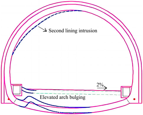
Large deformation was found in the YK209 + 500-YK210 + 030 section of the tunnel in 2019 as shown in Figure 1.
Such large deformation includes: 1) bulges and cracks occur in the left foot of the invert arch. Boreholes in the invert arch found outstanding bulges in the back-filled part of the left half of the arch, separation in the range of 50–100 cm from the side wall, and bending of steel bars inside the invert arch. The maximum height of a bulge of the invert arch exceeds 60 cm. 2) intrusions occur in the lining structure from the left arch foot to the right arch waist. Most intrusions reaches 15 cm. The highest intrusion reaches 26.1 cm, and there are more intrusions on the left side of the line structure than on the right side.
3 Mudstone physical and mechanical tests and ground stress tests
The hydraulic fracturing method was used to test the initial ground stress of the surrounding rock. The hydrofracturing method offers several distinct advantages: It enables deep measurement capabilities; The data compilation process does not necessitate the inclusion of rock elasticity parameters, thereby reducing errors caused by inaccurate parameter estimations; A wide stress distribution on the rock walls, attributed to the lengthy pressurized borehole section, mitigates the limitations associated with point stress conditions and heterogeneous geological factors; The method is characterized by its simplicity of operation and short testing duration. The principle underlying the hydrofracturing method for stress testing involves the use of expandable rubber packers. These packers isolate a borehole section at a predetermined depth, into which a liquid is then pumped to apply pressure. The in situ stress is determined by analyzing the characteristic pressure values from the pressure curve during the fracturing process.
The ground stress test was carried out in the section of the tunnel where outstanding deformations occur. In the test area, the maximum horizontal principal stress is 1.0–2.2°MPa, the minimum horizontal principal stress is 0.7–1.8°MPa, and the vertical stress is 5.1–5.9 MPa. On the whole, the stress field shows that the dead-weight stress is larger than the horizontal stress, indicating that the ground stress field in this area is dominated by dead-weight stress.
4 Analysis of tunnel wall rock deformation monitoring data
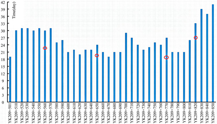
As shown in Figure 2, in the YK209 + 500-YK209 + 850 section of the tunnel, 36 observation sections are arranged with an interval of 10 m. The monitoring period commenced upon the completion of the initial lining and ends upon the pre-application of the secondary lining. The monitoring period of a section ranges from 18 days to 41 days.
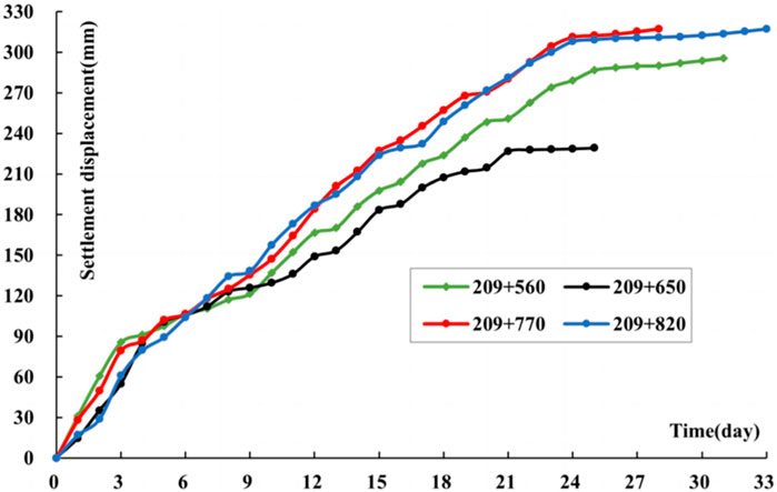
It can be seen from Figure 3 that the settlement displacement of the arch at a measuring point increases in an nonlinear way with time. When the monitoring starts, the settlement displacement rate is relatively huge. In the first 3 days, the displacement rate is 15–32 mm/d, and the value reduces slightly to about 2.5–20 mm/d between the 4th and 20th days. As the time goes by, the value reduces further. On the 25th day of monitoring, the settlement displacement rate is less than 2.0 mm/d.
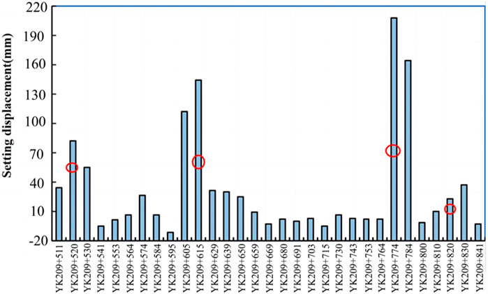
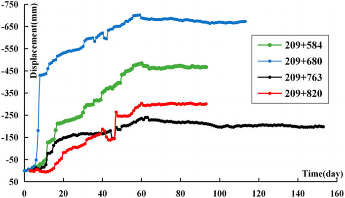
As can be seen from Figure 4, 5, during the secondary lining stage, the settlement displacement of the arch top in the YK209 + 511-YK209 + 841 section is mostly between 5 and 40mm, and the average value is about 32.0 mm. Figure 5 reveals that the highest bulges on the invert arch is mostly 300–650°mm, the maximum deformation is 702°mm, the minimum is 28°mm, and the average is 319.5 mm. After the secondary lining is done, the settlement displacement of the arch top is still time-dependent. On the whole, the bulges of the invert arch is larger, and the deformation of the surrounding rock at the bottom shows strong rheological properties. The deformation velocity of the invert arch gradually flattens, and the displacement gradually stabilizes as the time goes by.
5 Study on the mechanism of large deformation damage of mudstone
Considering mudstone’s water-softening property and obvious rheological characteristic, we applied the numerical simulation to the tunnel at different support stages by using FLAC3D to study the deformation mechanism, structural stress characteristics and creep development law of the tunnel’s surrounding rock, and to explore the mechanism of their large deformation.
5.1 Rock viscous-elastic-plasticity constitutive model
In the study, a creep-viscoplastic model, which comprises the Burgers model and Mohr Coulomb model is used. The former, which simulates the time-dependent creep characteristics of rock and soil, can reflect the attenuating creep stage and stable creep stage of a material after loading. The latter considers viscoelastic-plastic stress deviation characteristics and the elastic-plastic volume change of a material. It is assumed that the viscoelastic strain rate component and plastic strain rate component act together in series. The viscoelastic component corresponds to the Burgers model (composing Kyle style and Magswell body in series), while the plastic component is consistent with the Mohr-Coulomb model. When the stress is less than the yield stress, the viscoelastic deformation of the model equals to the creep equation of the Burgers model, and when the stress is greater than the yield stress, the plastic flow deformation shall also be governed by the Mohr-Coulomb criterion.
To ensure the effectiveness of the finite element model used in this study, a creep-viscoplasticity model was adopted, providing a comprehensive and reliable method for simulating and analyzing the behavior of geotechnical materials, as illustrated in Figure 6. The validity of the model was confirmed by calibrating its parameters using experimental data, thereby ensuring the consistency of the model’s predictive results with actual scenarios.

FIGURE 6. Burgers creeping viscoelastic-plastic model σ is the rock stress, EM, EK, ηM, and ηK are the rock’s elastic modulus, viscoelastic modulus, Maxwell viscosity coefficient, and Kelvin viscosity coefficient, respectively, σf is the yield strength of the rock, and εM, εK, and εP are the strain and plastic strain of the Maxwell body and Kelvin body.
The plasticity criterion uses a composite criterion combining Mohr-Coulomb shear damage and tensile damage, where the yield function of the Mohr-Coulomb criterion is:
The maximum tensile stress criterion yield function is:
Where
5.2 Model generalization and calculation conditions
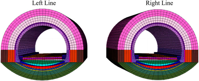
The model’s boundary of both tunnels are 68 m away from the center line. Its top is 60 m away from the center of the tunnel and the bottom is 50 m away from the central point. The model’s length is 20 m along the axis of the tunnel. In the simulation, the number of units is 151,800 and the number of nodes is 161,637 as shown in Figure 7. The diameter of the excavation in the mudstone is 12.38m, while its inner diameter behind the lining is 10.86m, and its buried depth is about 237 m.
The design lining structure of this tunnel is SVb: I20a steel I-beam, spacing 100cm, 26 cm C25 shotcrete, Φ6 double layer mesh, 3.5 m long R25 hollow grouting anchors, spacing 75 cm × 100 cm, 50 cm C30 reinforced concrete lining and 10.25 m × 5 m design building limit of the main cavern.
The designed lining structure of the tunnel is SVb: I20a I-steel, spacing 100cm; 26 cm-thick C25 shotcrete, Φ6 double-layer steel mesh, 3.5 m-long R25 hollow grouting anchor, spacing 75°cm × 100°cm; 50 cm-thick C30 reinforced concrete lining. The designed limitation of the main tunnel is 10.25°m × 5 m.
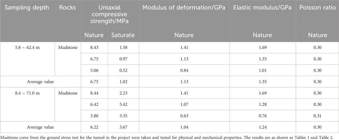
With reference to mudstone’s laboratory test results and the values of physical and mechanical parameters adopted in tunnel projects in Gansu province contained in previous literature, the values of physical and mechanical parameters of mudstone in natural and saturated states used in this study are as shown in Tables 1–3.
5.3 Inversion of the rheological parameter of mudstone
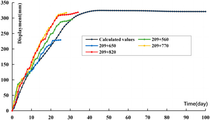
It is complicated to determine the rheological parameters of the tunnel’s surrounding rock. In this paper, the numerical calculation and on-site deformation monitoring data were used for curve fitting to inverse the mudstone’s rheological parameters. The inversion results of the rheological parameters of mudstone in natural state are as shown in Table 4.
The time-based curve of mudstone’s rheological inversion and monitoring displacement is as shown in Figure 8. The deformation around the tunnel mostly occurs in the initial support. At first, the maximum deformation rate around the tunnel is about 18 mm/d. In the first 10°days, the deformation rate is relatively large, basically in the range of 7.0–18.0 mm/d. As the time elapses, the deformation rate decreases gradually. The rate decreased to 2.0–7.0 mm/d between the 11th and 20th days. By the 40th day, the rate was basically less than 1 mm/d. At this time, the deformation around the hole tends to be stable.
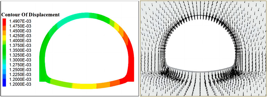
After the initial lining of the tunnel is done, the second lining will be applied after the deformation of the surrounding rock is basically stable. As can be seen from Figure 9, the long-term deformation of the lining structure is about 1.2–1.5 mm. Displacements in all directions are all towards the center of the tunnel, and these displacements and their values on both sides of the vertical line are basically symmetrical. Both the top arch and the invert arch deform downward under the action of dead weight. The lining stress is small. The maximum compressive stress is about 0.6°MPa, the tensile stress is about 0.2°MPa, and the relatively large stress appears in the arch feet on both sides of the arcs.
5.4 Deformation and stress state hole cycle after softening of water seepage in the wall rock
The groundwater was not exposed during tunnel excavation. However, as the time goes by, the groundwater seeped along mudstone cracks after the excavation for invert arch in some sections, and then some unstable deformations occur such as cracks in the invert arch and convergence in the tunnel’s wall rock. During the on-site investigation, the groundwater was also found in the boreholes in the problematic sections and in the slots of the invert arch, but the groundwater distribution was uneven. The infiltration of groundwater is the root cause of problems in the tunnel.
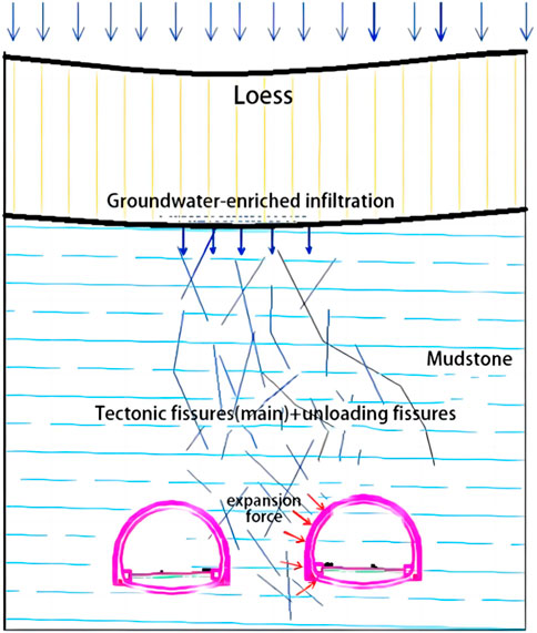
The development of structural planes such as joints and cracks in the problematic section leads to the breakage of the rock mass. The groundwater in a changed environment slowly seeps into the surrounding rock and results in the gradual immersion and softening of the surrounding rock and its weaker strength, as shown in Figure 10. After the completion of the tunnel structure, the natural discharge of groundwater along the cracks is blocked, and the groundwater is mainly concentrated in the rock pillar area about 30 m between the left and right tunnels and at the bottom of the tunnel. Mudstone is also a kind of rock prone to interact with water. Under the action of water, the growth and expansion of macroscopic fissures is the main reason for the rapid deterioration of the main physical and mechanical parameters of mudstone. Under the same confining pressure, the higher the water content of mudstone is, the more obvious the aging characteristic is.
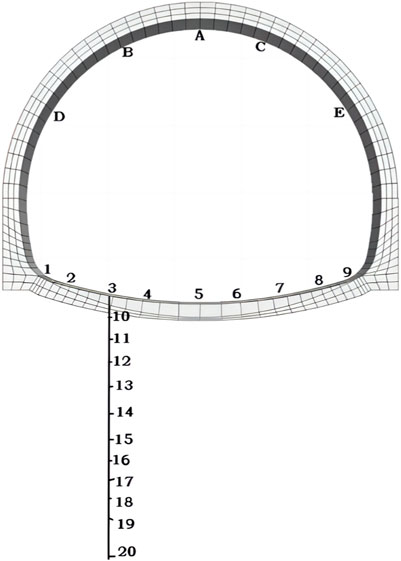
In order to accurately express the research results, a number of measuring points are installed in the lining’s top arch, arch shoulder, arch waist and invert arch. The measuring points #1 - #9 are evenly distributed on the invert arch. The buried measuring points #10-#20 are on #3’s vertical line. The distance between #3, #10 - #19 are in an interval of 2 m while that between #19 and #20 is 5 m. The distance between #3 and #20 is 25 m. The layout of these measuring points are as shown in Figure 11.
The measuring point A, on the top of the lining arch, has a downward displacement of about 58.9 mm. The measuring points B and C has a downward displacement of 140.1 mm and 29.3 mm respectively and a horizontal convergence deformation of about 48 mm. The downward displacements of D and E are 173.4 mm and 23.0 mm respectively while their horizontal convergence deformation is about 95.5 mm. Intrusions on the left side of the second lining of the tunnel is obvious. Most of them are more than 10 cm, and the maximum intrusion is more than 20 cm. The deformation of the tunnel in the problematic section is characterized by the arch’s downward displacement, convergence at the waist on both sides, and inclined bulges on the invert arch with the ones on the left higher than those on the right. It can be seen that the plastic flow caused by water-softening of the rock pillar mudstone is the main factor of the large deformation of the tunnel.
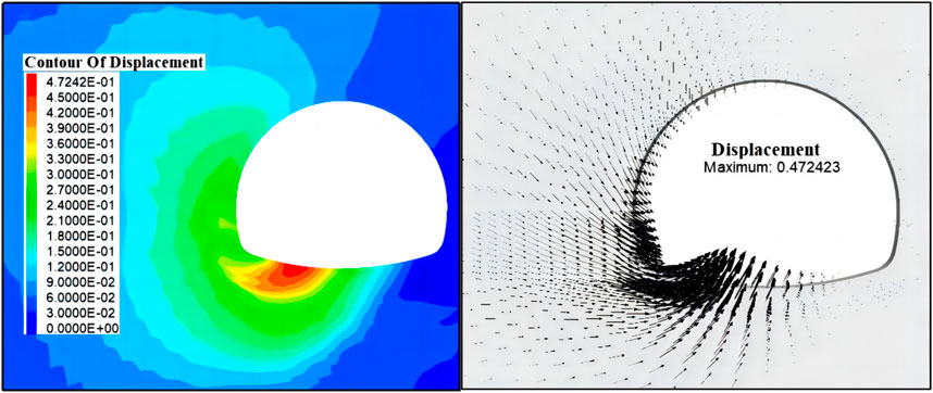
As shown in Figure 12, when the mudstone on the left side of the tunnel is saturated with and softened by water, its strength is obviously weakened, and the surrounding rock produces a large squeezing deformation on the left side of the supporting structure. The deformation of the left arch foot and the left arch bottom of the lining is about 250–470°mm, and the deformation of the left arch is about 150–300 mm.
As shown in Figure 13, among the nine measuring points arranged on the bottom of the invert arch, the measuring point #3, which is about 2.0 m away from the left arch foot, has the largest bulge displacement of 383 mm. The bulge displacement of the left arch foot is about 30mm, while the right arch foot sinks slightly, and the downward displacement is about 12 mm. The deformation along the measuring point #3’s vertical line shows that the upward displacement of the floor along such line gradually decreases. The rheological effect of the shallow surrounding rock of the invert arch is obvious, and the time-based curve of mudstone softening and creep deformation rate increases at first, and then decreases to zero gradually.
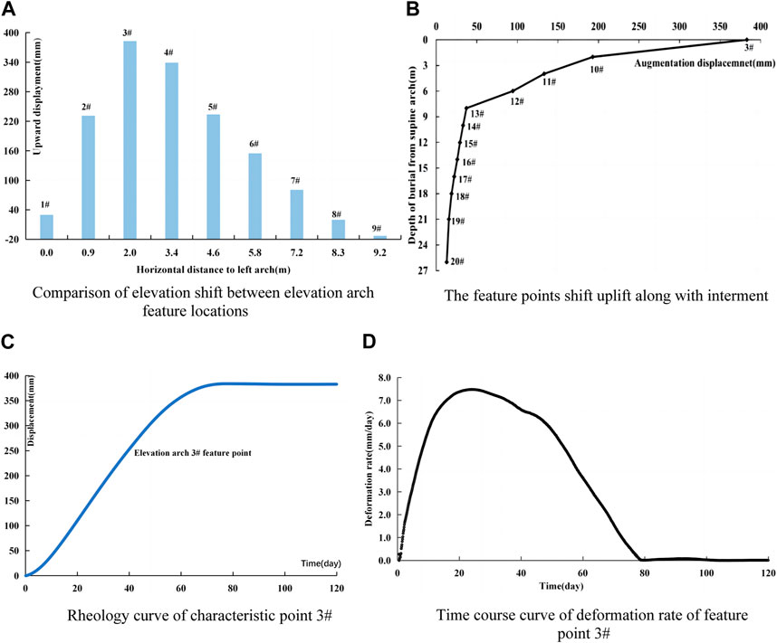
FIGURE 13. Arch Feature Displacement. (A) Elevation Shift Comparison. (B) Feature Points Uplift. (C) Rheology Curve (Point 3#). (D) Deformation Rate Curve (Point 3#).
The lining structure as a whole is in a compressed state, and the compressive stress concentration is high at both ends of the arch foot and bottom plate. The maximum compressive stress near the left and right arch feet are 17.0°MPa and 20.0 MPa respective. And it is 2.0–9.0 MPa at the bottom of the arch, 5.0–8.5 MPa at the left arch, about 4.0–11.0 MPa at the right arch, and about 7.0–13.0 MPa at the top of the arch.
The uneven deformation around the tunnel caused by mudstone softening acts on the lining structure. The latter bears large deformation pressure, and the force is unevenly distributed due to the difference of deformation. Looking at the overall stress of the lining structure, the stress on the arch foot and the arch top is larger, and the tension at the lower part of the left arch waist is obvious, which is easy to cause the tension crack and damage of the lining structure in the stress concentration and tension stress area of the arch foot.
6 Conclusion
The main results of this paper are as follows:
1) The tunnel’s problematic section of large deformation is located in the core of the wide and gentle syncline. Due to the tectonic action, the joints and cracks are developed and the rock mass is broken, and the unloading of tunnel excavation leads to the opening and expansion of the primary cracks in the left and right rock pillars. At the same time, the pore groundwater in the overlying loess seeps down along the joints and cracks and invades the surrounding rock of the tunnel.
2) Mudstone has strong hydrophilicity and weak expansibility, which will lead to increase and expansion of macroscopic fissures, a sharp decrease in physical and mechanical characteristics. Mudstone’s aging deformation characteristics become more obvious as the content of water increases. Further research indicates a close interplay between the softening mechanisms of the surrounding rock and changes in stress distribution. Particularly in water-sensitive rocks such as mudstone, the permeation of moisture leads to a reduction in the strength of the surrounding rock and a redistribution of stress, thereby exacerbating the instability of rock layers around tunnels.
3) Computational comparative analysis reveals that the depth of the tunnel and stress levels exert a relatively significant influence on the unloading deformation of the surrounding rock, the magnitude of time-dependent deformation, and the convergence time. Conversely, the impact of swelling forces is comparatively minor, and they are not the primary controlling factors for substantial deformation and cracking of the lining in the surrounding rock.
When preparing suggestions for the treatment of a tunnel, it is necessary to improve the interception and drainage measures of the tunnel to ensure smooth drainage. It is also necessary to strengthen the weak surrounding rock at a certain depth around the tunnel in order to improve the strength and anti-deformation ability of rock mass. It is also recommended to strengthen the stress and strain monitoring of the tunnel lining and the monitoring of drainage facilities, and dynamically track and analyze the long-term stability of the tunnel by means of real-time monitoring, so as to provide security for the normal operation of the tunnel.
Data availability statement
The original contributions presented in the study are included in the article/Supplementary material, further inquiries can be directed to the corresponding author.
Author contributions
SL: Writing–original draft. FJ: Writing–review and editing. GL: Writing–review and editing. JZ: Writing–review and editing.
Funding
The author(s) declare that no financial support was received for the research, authorship, and/or publication of this article.
Conflict of interest
Author GL was employed by CCCC Second Highway Consultants Co., Ltd.
The remaining authors declare that the research was conducted in the absence of any commercial or financial relationships that could be construed as a potential conflict of interest.
Publisher’s note
All claims expressed in this article are solely those of the authors and do not necessarily represent those of their affiliated organizations, or those of the publisher, the editors and the reviewers. Any product that may be evaluated in this article, or claim that may be made by its manufacturer, is not guaranteed or endorsed by the publisher.
References
1. Fan S, Song Z, Li X, Zhang Y, Liu L. Investigation into the large deformation mechanism and control technology of variable cross-section tunnel in layered mudstone stratum. Buildings (2022) 13(1):110. doi:10.3390/buildings13010110
2. Liu D, Huang S, Ding X, Chi J, Zhang Y. Characteristics and mechanism of large deformation of tunnels in tertiary soft rock: a case study. Buildings (2023) 13(9):2262. doi:10.3390/buildings13092262
3. Sun Z, Zhang D, Li M, Guo F. Large deformation characteristics and the countermeasures of a deep-buried tunnel in layered shale under groundwater. Tunnelling Underground Space Tech (2024) 144:105575. doi:10.1016/j.tust.2023.105575
4. Ma K, Zhang J, Zhang J, Dai Y, Zhou P. Floor heave failure mechanism of large-section tunnels in sandstone with shale stratum after construction: a case study. Eng Fail Anal (2022) 140:106497. doi:10.1016/j.engfailanal.2022.106497
5. Wang K, Xu S, Zhong Y, Han Z, Ma E. Deformation failure characteristics of weathered sandstone strata tunnel: a case study. Eng Fail Anal (2021) 127:105565. doi:10.1016/j.engfailanal.2021.105565
6. Zhou S, Tian Z, Di H, Guo P, Fu L. Investigation of a loess-mudstone landslide and the induced structural damage in a high-speed railway tunnel. Bull Eng Geology Environ (2020) 79:2201–12. doi:10.1007/s10064-019-01711-y
7. Wang M, Zhang N, Li J, Ma L, Fan P. Computational method of large deformation and its application in deep mining tunnel. Tunnelling Underground Space Tech (2015) 50:47–53. doi:10.1016/j.tust.2015.06.006
8. Chen J, Liu W, Chen L, Luo Y, Li Y, Gao H, et al. Failure mechanisms and modes of tunnels in monoclinic and soft-hard interbedded rocks: a case study. KSCE J Civil Eng (2020) 24:1357–73. doi:10.1007/s12205-020-1324-3
9. Meng X, Qi T, Zhao Y, Dijkstra T, Shi W, Luo Y, et al. Deformation of the Zhangjiazhuang high-speed railway tunnel: an analysis of causal mechanisms using geomorphological surveys and D-InSAR monitoring. J Mountain Sci (2021) 18(7):1920–36. doi:10.1007/s11629-020-6493-5
10. Liu X, Liu F, Song K. Mechanism analysis of tunnel collapse in a soft-hard interbedded surrounding rock mass: a case study of the Yangshan Tunnel in China. Eng Fail Anal (2022) 138:106304. doi:10.1016/j.engfailanal.2022.106304
11. Chen Z, He C, Wang J, Ma C. Time-dependent squeezing deformation mechanism of tunnels in layered soft-rock stratum under high geo-stress. J Mountain Sci (2021) 18(5):1371–90. doi:10.1007/s11629-020-6356-0
12. Zheng L, Zuo Y, Hu Y, Wu W. Deformation mechanism and support technology of deep and high-stress soft rock roadway. Adv Civil Eng (2021) 2021:1–14. doi:10.1155/2021/6634299
13. Yang SQ, Tian WL, Jing HW, Huang YH, Yang XX, Meng B. Deformation and damage failure behavior of mudstone specimens under single-stage and multi-stage triaxial compression. Rock Mech Rock Eng (2019) 52:673–89. doi:10.1007/s00603-018-1622-y
14. Guofeng LI, Manchao HE, Zhang G, Tao Z. Deformation mechanism and excavation process of large span intersection within deep soft rock roadway. Mining Sci Tech (China) (2010) 20(1):28–34. doi:10.1016/s1674-5264(09)60156-3
15. Bao H, Liu C, Liang N, Lan H, Yan C, Xu X. Analysis of large deformation of deep-buried brittle rock tunnel in strong tectonic active area based on macro and microcrack evolution. Eng Fail Anal (2022) 138:106351. doi:10.1016/j.engfailanal.2022.106351
16. Chen LL, Lian H, Liu Z, Gong Y, Zheng C, Bordas S. Bi-material topology optimization for fully coupled structural-acoustic systems with isogeometric FEM–BEM. Eng Anal Boundary Elem (2022) 135:182–95. doi:10.1016/j.enganabound.2021.11.005
17. Chen L, Li H, Guo Y, Chen P, Atroshchenko E, Lian H. Uncertainty quantification of mechanical property of piezoelectric materials based on isogeometric stochastic FEM with generalized n th-order perturbation. Eng Comput (2023) 1–21. doi:10.1007/s00366-023-01788-w
18. Chen LL, Lian H, Natarajan S, Zhao W, Chen X, Bordas S. Multi-frequency acoustic topology optimization of sound-absorption materials with isogeometric boundary element methods accelerated by frequency-decoupling and model order reduction techniques. Comp Methods Appl Mech Eng (2022) 395:114997. doi:10.1016/j.cma.2022.114997
19. Chen L, Lian H, Xu Y, Li S, Liu Z, Atroshchenko E, et al. Generalized isogeometric boundary element method for uncertainty analysis of time-harmonic wave propagation in infinite domains. Appl Math Model (2023) 114:360–78. doi:10.1016/j.apm.2022.09.030
20. Chen L, Zhao J, Lian H, Yu B, Atroshchenko E. A BEM broadband topology optimization strategy based on Taylor expansion and SOAR method—application to 2D acoustic scattering problems. Int J Numer Methods Eng (2023) 124:5151–82. doi:10.1002/nme.7345
21. Chen L, Wang Z, Lian H, Ma Y, Meng Z, et al. Reduced order isogeometric boundary element methods for CAD-integrated shape optimization in electromagnetic scattering. Comp Methods Appl Mech Eng (2024) 419:116654. doi:10.1016/j.cma.2023.116654
22. Chen L, Cheng R, Li S, Lian H, Zheng C, Bordas SP. A sample-efficient deep learning method for multivariate uncertainty qualification of acoustic–vibration interaction problems. Comp Methods Appl Mech Eng (2022) 393:114784. doi:10.1016/j.cma.2022.114784
23. Chen LL, Zhang Y, Lian H, Atroshchenko E, Ding C, Bordas S. Seamless integration of computer-aided geometric modeling and acoustic simulation: isogeometric boundary element methods based on Catmull-Clark subdivision surfaces. Adv Eng Softw (2020) 149:102879. doi:10.1016/j.advengsoft.2020.102879
24. Chen L, Lu C, Lian H, Liu Z, Zhao W, Li S, et al. Acoustic topology optimization of sound absorbing materials directly from subdivision surfaces with isogeometric boundary element methods. Comp Methods Appl Mech Eng (2020) 362:112806. doi:10.1016/j.cma.2019.112806
25. Chen LL, Lian H, Liu Z, Chen H, Atroshchenko E, Bordas S. Structural shape optimization of three dimensional acoustic problems with isogeometric boundary element methods. Comp Methods Appl Mech Eng (2019) 355:926–51. doi:10.1016/j.cma.2019.06.012
26. Chen L, Liu C, Zhao W, et al. An isogeometric approach of two dimensional acoustic design sensitivity analysis and topology optimization analysis for absorbing material distribution. Comp Methods Appl Mech Eng (2018) 336:507–32. doi:10.1016/j.cma.2018.03.025
27. Shen X, Du C, Jiang S, Sun L, Chen L. Enhancing deep neural networks for multivariate uncertainty analysis of cracked structures by POD-RBF. Theor Appl Fracture Mech (2023) 125:103925. doi:10.1016/j.tafmec.2023.103925
28. Shen X, Du C, Jiang S, Zhang P, Chen L. Multivariate uncertainty analysis of fracture problems through model order reduction accelerated SBFEM. Appl Math Model (2024) 125:218–40. doi:10.1016/j.apm.2023.08.040
29. Lu C, Chen L, Luo J, Chen H. Acoustic shape optimization based on isogeometric boundary element method with subdivision surfaces. Eng Anal Boundary Elem (2023) 146:951–65. doi:10.1016/j.enganabound.2022.11.010
Keywords: highway tunnel, Mudstone, viscoelastic plastic, large deformation, intrusion limit, Softening
Citation: Li S, Fu J, Liu G and Zhou J (2024) Research on intrusion and large arch bulge in lining structure for highway’s mudstone tunnel. Front. Phys. 12:1345581. doi: 10.3389/fphy.2024.1345581
Received: 28 November 2023; Accepted: 29 January 2024;
Published: 08 February 2024.
Edited by:
Yilin Qu, Northwestern Polytechnical University, ChinaReviewed by:
Peng Yu, Guangxi University, ChinaFeng Zhu, Nanjing University of Aeronautics and Astronautics, China
Copyright © 2024 Li, Fu, Liu and Zhou. This is an open-access article distributed under the terms of the Creative Commons Attribution License (CC BY). The use, distribution or reproduction in other forums is permitted, provided the original author(s) and the copyright owner(s) are credited and that the original publication in this journal is cited, in accordance with accepted academic practice. No use, distribution or reproduction is permitted which does not comply with these terms.
*Correspondence: Shuai Li, bGlzaHVhaUBzLmRsdS5lZHUuY24=
 Shuai Li
 Jing Fu
 Gengren Liu
 Jinghu Zhou