- College of Mechanics and Materials, Hohai University, Nanjing, China
As the water pipe cooling system is widely applied to controlling temperature in mass concrete structures, the precise simulation of the temperature field in mass concrete with cooling pipes embedded is meaningful. This paper presents an isogeometric analysis (IGA) with NURBS for heat transfer in mass concrete with consideration of the cooling pipe. The proposed method not only achieves the same level of accuracy with fewer nodes but also eliminates the time-consuming process of mesh in the traditional FEM. The coarsest parameter space which depicts small pipe and large concrete precisely is constructed to create an efficient model for numerical computation. In addition, the unique k-refinement in IGA is supposed to be the most appropriate encryption mechanism, and the knot insertion vector for effective refinement is calculated by considering the characteristics of temperature gradient distribution around the cooling pipes. In addition, a different calculation parameter has been discussed to show the stability and flexibility of the IGA. The obtained numerical results demonstrate the accuracy and efficiency of the proposed scheme in the simulation of transient temperature fields in concrete structures with cooling systems.
1 Introduction
The embedded cooling pipe has been extensively used in engineering structures with mass concrete due to the significant effect on heat removal and crack control. It can effectively reduce the temperature difference between the surface and inner of the concrete structures, especially in the early stage of cement hydration [1–3]. However, the temperature gradient around the small pipes cannot be neglected. It generates remarkable thermal stress and increases the possibility of cracking [4]. Therefore, it is necessary to predict the temperature gradient and thermal field in concrete with cooling pipes.
How to improve efficiency in thermal field numerical simulation while maintaining accuracy? Various numerical methods have been developed to solve this problem, including the finite element method (FEM) [5–8], virtual element method (VEM) [9], composite element method (CEM) [10–12], boundary element method (BEM) [13], and singular boundary method (SBM) [14]. Among the methods mentioned earlier, the finite element method is the most widely applied method to simulate the cooling system. It is generally employed to discretize the calculation domain into non-overlapping elements and take the polynomial basis functions as unknown fields. As a result, it is hard to exactly represent the small pipes in the large size of concrete. In addition, the dense grids in the FEM around the tiny pipes lead to a computationally intensive process and are time-consuming. Research workers create numerous improved approaches based on the FEM. Zuo [15] proposed an extended finite element method (XFEM) which is only used in the two-dimensional water pipe cooling problem. To avoid intensively meshing the small pipes, Kim [16] and Liu [17] chose to simply neglect the practical size and shape of the pipes by using a line element; as a consequence, the location of the pipes needed to leech on the node inconveniently. Liu considered the cooling pipe as a line element, and Chen [18] meshed the concrete by neglecting the location of the pipes and treated the pipes as an inner negative heat source after that. However, the accuracy of the temperature field still depends on the size of the element around the cooling pipe. To improve the effectiveness of calculations while ensuring accuracy, it is necessary to consider the typical temperature gradient distribution around the pipes and refine the grids selectively. In other words, dense elements are needed in regions with sharp temperature gradients, whereas sparse elements are suitable for other regions. However, the process of element partitioning is extremely time-consuming in methods like the FEM.
Instead of the FEM, this study introduces the isogeometric analysis (IGA) method to simulate the heat transfer process in mass concrete with cooling pipes. The IGA method, first introduced by Hughes [19], employs smooth and higher-order splines (such as non-uniform rational B-splines, T-splines [19], and LR-splines [20]) as basis functions to represent both the geometric space and approximation of solution fields. In the IGA context, the non-uniform rational B-splines (NURBSs) are most widely adopted to solve partial differential equations. There are several attractive characteristics [21] in NURBS-based IGA, such as great geometric accuracy, higher-order continuity, sparse matrix, and automatic mesh generation. Consequently, the IGA has been successfully applied in many research fields, for example, elasticity, shape optimization, crack propagation, and fluid flows [22–28]. In addition, many research workers utilize the IGA in heat conduction areas. Attracted by the unique quality, R. Duvigneau [29] summarized the advantages of the IGA by comparing it with the traditional FEM through the thermal conduction test case. Chen [30] solved the Dirichlet boundary processing error caused by the lack of interpolation of the NURBS basis function. Yu [31] improved the accuracy of the steady-state heat conduction problem with locally refined adaptive IGA, and An [32] combined IGA and BEM to solve the same problem. To reduce the problem dimension and obtain highly accurate results for the flux values on the boundaries, Özgür applied the IGA-BEM to the steady-state heat conduction with volumetric heat source and non-linear boundary conditions [33].
To the best of the author’s knowledge, the IGA has not been used in the temperature simulation of mass concrete with cooling pipes. This work attempts to simulate the mass concrete temperature fields with the IGA method for the following reasons: first, the tiny pipes and large concrete can be accurately represented, even with a coarse grid. Second, the higher-order basis functions are more suitable for the non-linear temperature gradient than the traditional polynomial interpolation [34]. Third, it is convenient that there are no more efforts needed for mesh or pretreatment. Finally, the flexible refinement of IGA is appropriate for the different grid density requirements of complex temperature gradients and complicated surrounding conditions.
In this paper, IGA based on the NURBS is exploited to simulate the temperature field of two-dimensional mass concrete with one cooling pipe, as the preparation for cubic with multiple cooling pipes. The parameter space which describes small pipe and large concrete precisely is presented to generate an efficient model for calculation. The advantages of the suggested parameter space are shown by comparing it with others. Taking the correspondence between temperature gradient and distance from the pipe into account, the area in which temperature gradient changes dramatically around the cooling pipe is suggested, and the knot insertion vector for grid encryption is proposed. Furthermore, the situations with different calculating parameters such as water temperature, pipe thickness, and time step are investigated. The environmental conditions around concrete are also considered to demonstrate the flexibility of IGA.
The contents of this paper are as follows: Section 2 introduces the fundamental equations for transient heat conduction. Section 3 describes the IGA method and presents the parameter space utilized in mass concrete. Section 4 demonstrates the accuracy and performance of the simulation with several numerical examples. Finally, the conclusion is presented in Section 5.
2 Governing equation
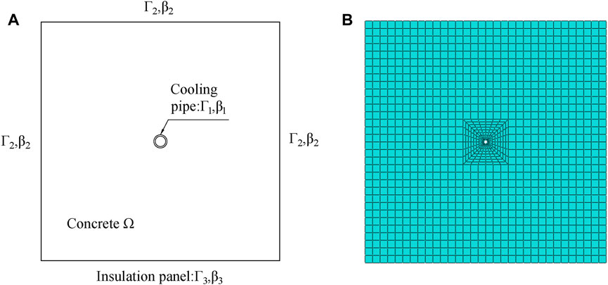
The simplified mathematical model for the typical two-dimensional mass concrete with cooling pipes embedded is shown in Figure 1.
As can be seen in Figure 1A, there is a cooling pipe assumed as a negative heat resource [18] at the center of the concrete domain
In Eq. 1,
where the initial temperature of concrete
According to the governing equation and boundary conditions mentioned in Eqs 3–5, the functional appeared by applying Galerkin’s method and integration by parts.
In Eq. 6,
3 Isogeometric analysis
In this section, we first give a brief introduction to NURBS as the foundation of the IGA. After that, IGA formulation for thermal field in mass concrete with cooling pipe is to be discussed. Finally, the most suitable IGA calculation model and refinement for numerical simulations are presented.
3.1 B-spline basis function and refinement
Different from the FEM, the IGA generates mesh by constructing parametric surface (volumes, in terms of three dimension) with CAD basis function like B-spline or NURBS. It provides some unique advantages to the isogeometric analysis, such as geometric exactness and simple refinements.
As NURBS is built from B-spline, it is necessary to introduce the definition and character of B-spline. The B-spline is defined in parametric space named knot vector
and
Based on the B-spline basis function described in Eqs. 7, 8, the NURBS basis function is defined as follows:
Moreover, the basis function of the NURBS surface is given by
where
There are several crucial properties that emerged from the basis functions above. The first one is that each basis function is non-negativity and constitutes partition of unity. The second main property to note is compact support, that is,
Given
Similarly, a tensor product NURBS surface is defined by
As shown in Eqs 11, 12, the NURBS curve (surface) is approximated by a control polygon consisting of control points and the control polygon is not unique. As a result, the choice of control points should be based on the geometric features of the objective curve like endpoints and inflection points. The weights at control points reflect the distance from the curve to the control polygon.
Similar to the FEM, appropriate refinement should be taken to ensure the computational accuracy; however, a coarse mesh could guarantee the geometric exactness in the isogeometric approach. Three main means are used frequently to enrich the basis function, namely, knot insertion, order elevation, and k-refinement. Here, a brief introduction to the approach is given.
The first means is knot insertion by which a new knot
where
Unfortunately, the continuity of the curve based on
3.2 IGA formulation for thermal field
In the IGA method, the tensor products of the NURBS basis function are defined in the parametric space
In the non-zero mesh
where
where
where
To discretize the time, the difference method is employed in Eqs 21, 22 . It is supposed that the temperature changes linearly at each time step
and
As the solution based on the backward difference method is unconditionally convergent, we take
The transient temperature field of mass concrete with the cooling pipe embedded is obtained through Eq. 25.
3.3 Mathematical model in IGA
The different size between the large scale of concrete and the small diameter of water pipe makes it hard to ensure the geometric accuracy in this problem, which greatly affects the results of numerical simulation. In the IGA, the parameter space is able to depict geometry exactly at all levels of discretization. As a result, this method is expected to acquire improved accuracy as compared with less geometrically precise methods. Moreover, the most time-consuming part is bypassed as the process of discretization is accomplished when the parameter space is determined. However, the parameter space is non-unique to model the same physical space, and the different parameter space has a significant impact on the accuracy and efficiency. This makes the suitable choice of parameter space important in the IGA.
The strategy of this study is that minimal control points are taken to represent geometry in detail and the refinement based on the temperature gradient in the mass concrete is implemented on those control points. The typical mathematical model for the two-dimensional mass concrete can be seen in Figure 1A, and it also can be assumed as an infinite plate with a circular hole. For simplicity of the expression, the parameter space is only constructed with a quarter of the plate. To depict the circular hole as water pipe, the polynomial order in
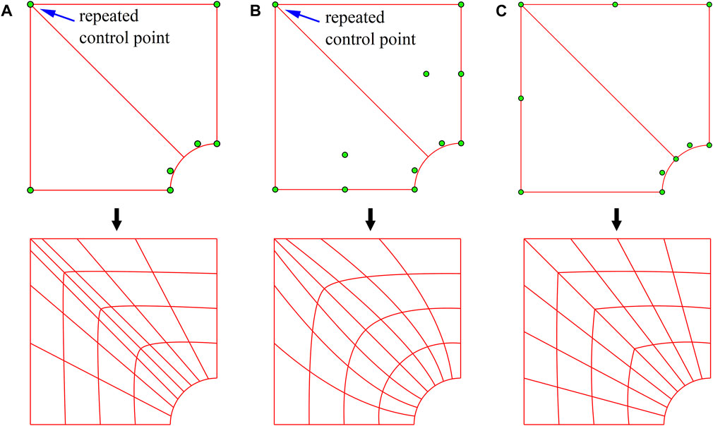
For the purpose of a well-proportioned mesh, the recommended parameter space is given in Table 1, in which five control points are adopted in
The mechanisms of NURBS refinement also play an important part in the construction of parameter space. J.A. Cottrell [34] found that the k-refinement method achieves a significant improvement in accuracy in the problems of structural vibrations over the classical
At last, the new knot vector should be established flexibly according to the temperature gradient in the practical condition. It is assumed that there is a cylindrical region named A around the water pipe in which the temperature gradient is perpendicular to the cooling pipe surface and has no relationship with the boundary conditions. This region is time-varying and the higher temperature gradient appears near the water pipe. In consequence, the dense elements are needed in region A and the parameter space is only refined in
In the Eq. 26,
4 Numerical experiments
In this section, three examples are given to examine the accuracy, stability, and sensibility of the proposed parameter space in the IGA. To evaluate the numerical results, the relative error (RE) and the relative root mean square error (RMSE) are applied, and the definition is expressed as Eqs 29, 30.
where
4.1 Example 1
There is a two-dimensional square concrete with length
Based on the formulation mentioned in part 3.3, we take
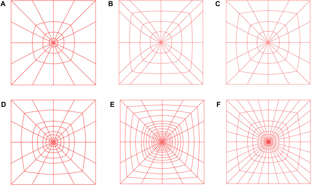
Figure 4. Mesh based on different parameter spaces: (A) initial model of proposed, (B) model with repeated control points and uniform distance, (C) initial model with uniform distance, (D)
Table 3 shows the numerical solutions of different models with almost the same number of degrees of freedom in the IGA and the exact solution in the FEM with 1256 numbers of nodes. The temperature of the three test points at different times is given. By comparing the RMSE of the first two models, it is clear that the repeated control points result in malformed meshes that lead to low accuracy. From the results obtained by the two models with the same number of degrees of freedom, it can be found that encryption based on temperature gradients can increase the accuracy with any additional effort. Moreover, the good accuracy of the proposed parameter space can be found and in that the RMSE can reach up to 8.22E-3, even though only 297 control points are used in the IGA. These results suggest that the construction of the proposed parameter space is reasonable and necessary in this paper.

Table 3. RMSE of numerical solution varies with the model under different test points and time, for example 1.
To verify the convergence of the initial model and the rationality of encryption approach selection, different means of refinement established on the initial model are displayed in Figures 4D–F. For concise expression, we named k-refinement in
Figure 5 shows the relative error of the time variable for different refinement means at the given test points. In addition, the total time consumed is provided in Table 4. Incidentally, these tests are performed using an Intel Core i5 2.4 GHz. It can be seen that the coarse grid applied in the initial model results in a relative error increment and finally reaches a 1.6E-2 error. After k-refinement in

Figure 5. Relative error of different refinement means over time: (A) Test point Q1, (B) Test point Q2, and (C) Test point Q3, for example 1.
From the discussion aforementioned, the parameter space for
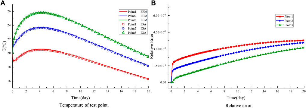
Figure 6. Comparison of the obtained temperature (A) and relative error (B) with different points by the proposed scheme and the FEM, for example 1.
4.2 Example 2
The main focus of this example is to figure out the sensitivity of the IGA to thickness, water temperature, and time step. Concrete length
To display the influence of water pipe thickness, the numerical results with different thicknesses of the proposed scheme and the FEM in the test points are enumerated in Table 5. It can be found that the thickness has a considerable influence on the temperature, and the effect of the cooling pipe decreases as the thickness increases. The RMSE converges to a level around 1E-3 although the heat convection coefficient for the surface contacted with water pipe is crudely represented by the coefficient of equivalent heat convection.

Table 5. Comparisons between temperature obtained from the proposed scheme and the FEM in test points with different thicknesses and time, for example 2.
Table 6 lists the comparison between the temperature obtained from the IGA with different water temperatures and those obtained from the FEM at the test points. It can be seen that colder water reduces the temperature observably at each test point and time. However, the increased temperature difference between water and concrete produces large temperature gradient which results in the increase in RMSE and the risk of cracking.

Table 6. Temperature and RMSE in test points with different water temperatures and times for IGA and FEM, for example 2.
Table 7 displays the temperature with different time steps by the proposed scheme compared with the FEM. The stability of time step for the proposed scheme has been proven from the results above. With increasing time steps, the temperature increases slightly in both the IGA and FEM, and the RMSE remains unchanged. From the numerical solutions listed in the three tables above, the accuracy and stability of the given model in IGA have been demonstrated.

Table 7. Temperature and RMSE in those test points mentioned above with different time steps and times for IGA and FEM, for example 2.
4.3 Example 3
In the last example, the temperature field for the proposed scheme is illustrated comprehensively in the concrete domain instead of the test points, and the boundary in contact with air is considered as a simulation of the practical engineering situation. Heat convection coefficient
To further verify the accuracy of the IGA, Figure 7 presents the temperature field at several time histories by the IGA compared with the FEM. We can see that the distribution of the temperature field is almost the same in the IGA and FEM. At the beginning of the experiment, the temperature of the concrete around the surface increases although the center is affected by the cooling pipe. With the heat of hydration proceeding, the temperature in most areas of the concrete is increased remarkably, and the temperature gradient around the pipe is changed sharply. When it comes to the time of 20 days, the temperature around the cooling pipe decreases after the peak of the hydration reaction. Despite the process being complicated, a good consistency can be observed between the temperature field of the offered scheme and the FEM. The slight difference in the bottom of the concrete is caused by the coarse grids used in boundary
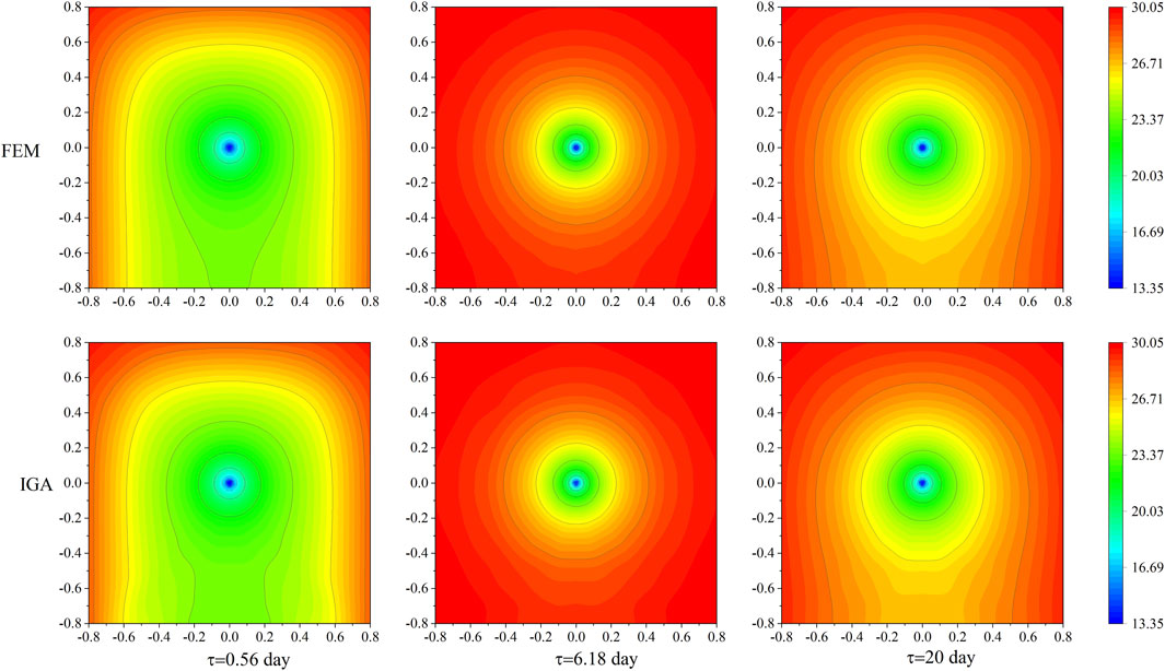
Figure 7. Comparison of the obtained transient temperature field by the proposed scheme and the FEM, for example 3.
Figure 8 displays the absolute relative error correspondingly. It can be found that the relative error steadily converges to a level around E-3 in most regions over several time histories although the largest error near 4E-2 is concentrated around the cooling pipe. This phenomenon is mostly caused by the approximate representation of the cooling pipe effect and the large temperature gradient around the pipe. All the results in this example demonstrate the accuracy of the IGA in the entire concrete, as well as the flexibility to refine according to the different boundaries.
5 Conclusion
In this paper, the IGA method based on NURBS is introduced to simulate the transient temperature field in massive concrete with cooling pipe embedded. As a preparation for the multi-pipes in three-dimensional simulation, only a classical model of simplified two-dimensional concrete with one pipe is considered, where the cooling pipe is considered as a negative heat resource.
Based on the aforementioned classical model, the most concise parameter space that can precisely describe the simplified model is provided. Different mechanisms for encrypting parameter space are discussed, and the unique k-refinement has been proven to be the most efficient method. To improve the efficiency under the premise of ensuring accuracy, the characteristics of temperature gradient in this problem is considered and different levels of refinement are applied in constructing the parameter space. Furthermore, the parameter space also can be refined flexibly according to the actual boundary conditions, which is expected to reduce the time consumption. The construction of parameter space is not only to avoid the cumbersome and useless refinement but also to leap over the time-consuming process of the mesh.
Numerical examples are presented to verify the validity and applicability of the proposed scheme. The rationality of the constructed parameter space and the accuracy of the IGA are demonstrated through numerical results displayed in the first example. The stability for different calculating parameters is also indicated in the second example. In addition, the flexibility and applicability of the method are shown in the last example. As a result, the proposed parameter space in the IGA method is deemed to possess great potential in simulating the thermal field in mass concrete with a cooling pipe system.
Data availability statement
The original contributions presented in the study are included in the article/Supplementary Material; further inquiries can be directed to the corresponding author.
Author contributions
QL: writing–original draft. GC: writing–review and editing. FZ: writing–review and editing and resources.
Funding
The author(s) declare that no financial support was received for the research, authorship, and/or publication of this article.
Conflict of interest
The authors declare that the research was conducted in the absence of any commercial or financial relationships that could be construed as a potential conflict of interest.
The reviewer DL declared a shared affiliation with the author(s) to the handling editor at the time of review.
Publisher’s note
All claims expressed in this article are solely those of the authors and do not necessarily represent those of their affiliated organizations, or those of the publisher, the editors, and the reviewers. Any product that may be evaluated in this article, or claim that may be made by its manufacturer, is not guaranteed or endorsed by the publisher.
References
1. Kwak YH, Walewski J, Sleeper D, Sadatsafavi H. What can we learn from the Hoover Dam project that influenced modern project management. Int J Project Manage (2014) 32(2):256–64. doi:10.1016/j.ijproman.2013.04.002
2. Seo T-S, Kim S-S, Lim C-K. Experimental study on hydration heat control of mass concrete by vertical pipe cooling method. J Asian Architecture Building Eng (2015) 14(3):657–62. doi:10.3130/jaabe.14.657
3. Tasri A, Susilawati A. Corrigendum to “Effect of cooling water temperature and space between cooling pipes of post-cooling system on temperature and thermal stress in mass concrete” [J. Build. Eng. 24 (2019) 100731]. J Building Eng (2019) 26:100922. doi:10.1016/j.jobe.2019.100922
4. Yu X, Chen J, Xu Q, Zhou Z. Research on the influence factors of thermal cracking in mass concrete by model experiments. KSCE J Civil Eng (2017) 22(8):2906–15. doi:10.1007/s12205-017-2711-2
5. Cheng J, Li TC, Liu X, Zhao LH. A 3D discrete FEM iterative algorithm for solving the water pipe cooling problems of massive concrete structures. Int J Numer Anal Methods Geomechanics (2016) 40(4):487–508. doi:10.1002/nag.2409
6. Zhu B. The equivalent heat equation of pipe cooling in mass concrete considering influence of external temperature. J Hydraulic Eng (2003) 3(3):49–54. doi:10.3321/j.issn:0559-9350.2003.03.010
7. Zhu Y, Xu Z, He J, et al. A calculation method for solving temperature field of mass concrete with cooling pipes. J Yangtze River Scientific Res Inst (2003) 20(2):19–22. doi:10.1063/1.4982444
8. ConceiçãO J, Faria R, Azenha M, et al. A new method based on equivalent surfaces for simulation of the post-cooling in concrete arch dams during construction. Eng Structures (2020) 209. doi:10.1016/j.engstruct.2019.109976
9. Vacca G An H1-conforming virtual element for Darcy and Brinkman equations. Math Models Methods Appl Sci (2017) 28(01):159–94. doi:10.1142/s0218202518500057
10. Chen SH, Su P, Shahrour I. Composite element algorithm for the thermal analysis of mass concrete. Int J Numer Methods Heat Fluid Flow (2011) 21(4):434–47. doi:10.1108/09615531111123100
11. Zhong R, Hou G-P, Qiang S. An improved composite element method for the simulation of temperature field in massive concrete with embedded cooling pipe. Appl Therm Eng (2017) 124:1409–17. doi:10.1016/j.applthermaleng.2017.06.124
12. Sheng Q, Chao W, Zhenyang Z. A new composite element algorithm for the temperature filed of concrete containing cooling pipe. SHUILI XUEBAO (2015) 46(6):739–48. doi:10.13243/j.cnki.slxb.20140910
13. SimõES I, SimõES N, Tadeu A, Reis M, Vasconcellos C, Mansur W. Experimental validation of a frequency domain BEM model to study 2D and 3D heat transfer by conduction. Eng Anal Boundary Elem (2012) 36(11):1686–98. doi:10.1016/j.enganabound.2012.05.007
14. Wei X, Chen B, Chen S, Yin S. An ACA-SBM for some 2D steady-state heat conduction problems. Eng Anal Boundary Elem (2016) 71:101–11. doi:10.1016/j.enganabound.2016.07.012
15. Zuo Z, Hu Y, Li Q, Liu G. An extended finite element method for pipe-embedded plane thermal analysis. Finite Elem Anal Des (2015) 102-103:52–64. doi:10.1016/j.finel.2015.05.002
16. Kim JK, Kim KH, Yang JK. Thermal analysis of hydration heat in concrete structures with pipe-cooling system. Comput Structures (2001) 79:163–71. doi:10.1016/s0045-7949(00)00128-0
17. Liu X, Zhang C, Chang X, Zhou W, Cheng Y, Duan Y. Precise simulation analysis of the thermal field in mass concrete with a pipe water cooling system. Appl Therm Eng (2015) 78:449–59. doi:10.1016/j.applthermaleng.2014.12.050
18. Guorong C, Wentao X, Yun Y, et al. Computation method for temperature field of mass concrete containing cooling water pipes. Chin J Comput Phys (2012) 29:411–6. doi:10.19596/j.cnki.1001-246x.2012.03.015
19. Bazilevs Y, Calo VM, Cottrell JA, Evans J, Hughes T, Lipton S, et al. Isogeometric analysis using T-splines. Comput Methods Appl Mech Eng (2010) 199(5-8):229–63. doi:10.1016/j.cma.2009.02.036
20. Dokken T, Lyche T, Pettersen KF. Polynomial splines over locally refined box-partitions. Comput Aided Geometric Des (2013) 30(3):331–56. doi:10.1016/j.cagd.2012.12.005
21. Bazilevs Y, Da Veiga L, Cottrell J, et al. Isogeometric analysis: approximation, stability and error estimates for h-refined meshes. Math Models Methods Appl Sci (2006) 16(7):1031–90. doi:10.1142/S0218202506001455
22. Yoon M, Ha S-H, Cho S. Isogeometric shape design optimization of heat conduction problems. Int J Heat Mass Transfer (2013) 62:272–85. doi:10.1016/j.ijheatmasstransfer.2013.02.077
23. Gillebaart E, De Breuker R. Low-fidelity 2D isogeometric aeroelastic analysis and optimization method with application to a morphing airfoil. Comput Methods Appl Mech Eng (2016) 305:512–36. doi:10.1016/j.cma.2016.03.014
24. Fischer P, Klassen M, Mergheim J, Steinmann P, Müller R. Isogeometric analysis of 2D gradient elasticity. Comput Mech (2010) 47(3):325–34. doi:10.1007/s00466-010-0543-8
25. Akkerman I, Bazilevs Y, Kees CE, Farthing M. Isogeometric analysis of free-surface flow. J Comput Phys (2011) 230(11):4137–52. doi:10.1016/j.jcp.2010.11.044
26. Bhardwaj G, Singh IV, Mishra BK, Bui T. Numerical simulation of functionally graded cracked plates using NURBS based XIGA under different loads and boundary conditions. Compos Structures (2015) 126:347–59. doi:10.1016/j.compstruct.2015.02.066
27. Buffa A, Sangalli G, Vazquez R. Isogeometric analysis in electromagnetics_ B-splines approximation. Comput Methods Appl Mech Eng (2010) 199(17–20):1143–52. doi:10.1016/J.CMA.2009.12.002
28. Wang J, Zhang H, Zheng Y, Ye H. High-order NURBS elements based isogeometric formulation for swellable soft materials. Comput Methods Appl Mech Eng (2020) 363:112901. doi:10.1016/j.cma.2020.112901
29. Duvigneau R An introduction to isogeometric analysis with application to thermal conduction. INSTITUT NATIONAL DE RECHERCHE EN INFORMATIQUE ET EN AUTOMATIQUE (2012).
30. Chen T. Imposing dirichlet boundary conditions with point collocation method in isogeometric analysis. J Mech Eng (2012) 48(5):157–64. doi:10.3901/jme.2012.05.157
31. Yu T, Chen B, Natarajan S, Bui TQ. A locally refined adaptive isogeometric analysis for steady-state heat conduction problems. Eng Anal Boundary Elem (2020) 117:119–31. doi:10.1016/j.enganabound.2020.05.005
32. An Z, Yu T, Bui TQ, Wang C, Trinh NA. Implementation of isogeometric boundary element method for 2-D steady heat transfer analysis. Adv Eng Softw (2018) 116:36–49. doi:10.1016/j.advengsoft.2017.11.008
33. GüMüŞ ÖC, Baranoğlu B, Çetin B. Isogeometric and NURBS-enhanced boundary element formulations for steady-state heat conduction with volumetric heat source and nonlinear boundary conditions. Eng Anal Boundary Elem (2022) 145:299–309. doi:10.1016/j.enganabound.2022.09.021
34. Cottrell JA, Hughes TJR, Reali A. Studies of refinement and continuity in isogeometric structural analysis. Comput Methods Appl Mech Eng (2007) 196(41-44):4160–83. doi:10.1016/j.cma.2007.04.007
35. Hughes TJR, Cottrell JA, Bazilevs Y. Isogeometric analysis: CAD, finite elements, NURBS, exact geometry and mesh refinement. Comput Methods Appl Mech Eng (2005) 194(39-41):4135–95. doi:10.1016/j.cma.2004.10.008
36. Hong Y, Lin J, Cheng AHD, Wang Y, Chen W. Thermal analysis of heat transfer in pipe cooling concrete structure by a meshless RBF-FD method combined with an indirect model. Int J Therm Sci (2020) 152:106296. doi:10.1016/j.ijthermalsci.2020.106296
Keywords: isogeometric analysis, mass concrete, cooling pipe system, temperature field, heat transfer, temperature gradient
Citation: Li Q, Chen G and Zhu F (2024) Simulation of thermal field in mass concrete with cooling pipes based on the isogeometric analysis method. Front. Phys. 12:1338718. doi: 10.3389/fphy.2024.1338718
Received: 15 November 2023; Accepted: 22 April 2024;
Published: 24 May 2024.
Edited by:
Teoman Özer, Istanbul Technical University, TürkiyeReviewed by:
Dong Lei, Hohai University, ChinaFuzheng Gao, Shandong University, China
Ziqi Yu, Toyota Research Institute of North America, United States
Copyright © 2024 Li, Chen and Zhu. This is an open-access article distributed under the terms of the Creative Commons Attribution License (CC BY). The use, distribution or reproduction in other forums is permitted, provided the original author(s) and the copyright owner(s) are credited and that the original publication in this journal is cited, in accordance with accepted academic practice. No use, distribution or reproduction is permitted which does not comply with these terms.
*Correspondence: Qingwen Li, bGlxaW5nd2VuQGhodS5lZHUuY24=
 Qingwen Li
 Guorong Chen
 Fuxian Zhu