 Yunpeng Wang
 Yang Li
 Pingxue Li
95% of researchers rate our articles as excellent or good
Learn more about the work of our research integrity team to safeguard the quality of each article we publish.
Find out more
ORIGINAL RESEARCH article
Front. Phys. , 28 November 2023
Sec. Optics and Photonics
Volume 11 - 2023 | https://doi.org/10.3389/fphy.2023.1330573
This article is part of the Research Topic Advances in Infrared Lasers and Their Applications View all 9 articles
We demonstrate a high repetition rate, high average power narrow-linewidth fiber amplifier at 1.55 μm eye-safe waveband by using a very-large-mode-area active fiber doping Er and Yb, having a 60-μm-diameter core and a 600-μm-diameter inner cladding. A maximum average power reaches 16 W at a 10 kHz repetition rate for 600 ns pulses in the stimulated Brillouin scattering (SBS) free operation, which calculates to a 1.6 mJ pulse energy and 2.7 kW peak power. In addition, the peak power rises to 4.9 kW with 148 ns pulses at the onset of SBS. The signal peak is located at 1,551.15 nm with a 36 dB signal-to-noise ratio (SNR). In order to eliminate the pulse steepening, the pulse shaping technology using a triangular-like wave with a slower rising edge is applied on the input pulses. The half-width of the frequency-intensity spectrum from high-average-power fiber amplifier is about 1.02 MHz, approaching the Fourier transform limit.
High energy single-frequency fiber light sources at 1.5 µm eye-safe region, with MHz linewidth and several nanoseconds pulse duration, have become powerful means for laser lidars [1–5], remote sensing [6–8], and optical communication [9] due to their high efficiency, low power consumption, high compactness, high stability features, and mature device technologies. Especially in coherent wind lidars, 1.5 µm narrow linewidth fiber amplifiers have been applied in airport windshear detection to ensure the safety of aircraft takeoff and landing [10–12], wake vortices observing of wind turbine blades to improve wind energy utilization [13], and high-altitude turbulence to guarantee aircraft flight safety [14]. In 2002, Pearson et al. reported a 1.5 µm short-range pulsed wind lidar for a range of 300 m [15], whose light source employed a master oscillator power amplifier (MOPA) structure with a 50 µJ pulse energy for 50 ns pulse duration at 20 kHz by using Er, Yb co-doped fibers (EYDFs) with a 20 µm core diameter. In 2009, Dolfi-Bouteyre et al. demonstrated a 1.5 µm pulsed wind lidar to detect the aircraft wake vortex [16]. A range of 1.2 km was realized by using a multi-stage fiber amplifier with 120 µJ output energy for 800 ns pulses at 12 kHz. The last stage amplifier is composed of a large mode area (LMA) fiber that possesses a core/cladding diameter of 25/300 µm. In 2015, Lombard et al. proposed a 1.5 µm long-distance wind lidar with a record range of 16 km [17]. The pulse energy of fiber light source is up to 450 μJ, corresponding to a 650 ns pulse duration under a 10 kHz repetition rate by utilizing special phosphoaluminosilicate glass fibers with a 30 µm diameter core. To further increase the detection range of coherent laser lidars, the energy of the fiber light sources needs to be increased on the basis of high repetition frequency. However, the stimulated Brillouin scattering (SBS) effect is an insurmountable barrier in the process of boosting energy in narrow-linewidth pulsed fiber lasers.
The SBS threshold power is referred to effective mode area and fiber length [18, 19], which is inversely proportional to the fiber length and proportional to the effective mode area. Consequently, based on sufficient gain, there are two simple and efficient approaches to restrain the SBS effect, one is to expand fiber core diameter to enhance the mode area, the other is to adopting heavy doping concentration and short length gain fiber. The way to enhance the mode area can be summarized from the above-mentioned research advances in coherent laser lidar systems. In terms of the way of using heavy doping concentration and short length gain fiber, Akbulut et al. proposed a 1.55 µm light source of coherent laser lidar, producing high average power, without SBS [20]. Up to 1.3 mJ pulse energy was generated from the EYDF amplification structure by adopting short-length (20–30 cm) and high-gain phosphate-glass fibers with about 1,000 μm2 mode field area, corresponding to a 23 W average power for 600 ns pulses at 18 kHz. In other emitting wavebands of Er-doped fibers, the 1.57 µm high-energy narrow-linewidth fiber amplification system is the most suitable candidate of space-borne laser lidar for CO2 sensing due to its robustness and low consumption. In 2018, Lee et al. achieved 1.8 mJ, 510 ns narrow-linewidth pulses at 2.5 kHz generated from a multi-stage fiber amplifier system by adapting a custom large-core EYDF based on silicate glass with 45 µm diameter core and 55 cm length [21]. Through the above progresses, the core diameter of current Er-doped gain fiber applied in the 1.55 µm single-frequency fiber amplifiers is no more than 30 µm. In millijoule level Er-doped fiber amplifiers whether at 1.55 or 1.57 µm, the doping fibers are all specially customized, and the fabricating progress and technique are facing certain challenges.
In addition, the significant pulse steepening produced by the massive depletion of the population inversion over the timescale is often occurred in a mJ-level high gain fiber amplification system [22]. This steepening results in an extremely dominant peak power at the leading edge of pulse profile and a very slow descent along the falling edge, limiting the pulse energy boosting of the narrow linewidth laser amplifier due to SBS caused by the steep leading edge. Therefore, it is critical to mitigate the pulse steepening for high-energy narrow linewidth fiber amplifier. One effective way is to pre-shape the input pulse signal of the modulator to compensate the pulse steepening from the gain saturation. And different pulse shapes have different compensation effects. In addition, the pulse pre-shape method can also suppress the linewidth of the single-frequency pulsed lasers [23, 24].
In this paper, the pulse shaping, high average power single-frequency pulsed light delivered from a multi-stage fiber amplification system is obtained by employing a commercial very-large-mode-area EYDF based on silica substrate with 60 µm diameter and 600 µm cladding. The largest average power at the repetition rate of 10 kHz is up to 16 W for a 600 ns pulse, which corresponds to a 1.6 mJ pulse energy and 2.7 kW peak power. When the pulse duration is reduced to 148 ns, the peak power increases to 4.9 kW at the onset of SBS. By shaping the input pulse with a triangular-like wave, the pulse rising edge is relatively slow and pulse profile becomes symmetrical. The signal is located at 1,551.15 nm with a signal-to-noise ratio (SNR) of 36 dB. The half width of the frequency-intensity spectrum from the amplifier system is approximately 1.02 MHz at the highest average power.
The whole 1.55 µm high-energy narrow-linewidth EYDF laser amplification system consists of a pulsed seed source, two-stage preamplifier, and main amplifier, as illustrated in Figure 1A. Continuous-wave (CW) narrow-linewidth seed light is delivered from the distributed feedback (DFB) fiber amplifier (Connet Laser Technology Ltd.) with launching power of approximately 100 mW, a 3 dB spectral bandwidth of 3 kHz, a peak wavelength of 1,551.1 nm. The output light of DFB laser is modulated into 10 kHz pulsed light at the level of hundreds of microwatts through an analog-modulated acousto-optic modulator (AOM) triggered by a pulse-shaping electrical signal with an amplitude of 1 V. A section of polarization maintaining (PM) single-mode Er-doped fiber with the core/cladding diameter of 8/125 μm, pumped by a LD at 976 nm through a wavelength division multiplexer (WDM), is used to improve small signal power after modulation to 20 mW. The first-stage preamplifier employs a PM EYDF with core diameter, cladding diameter, and length of 10 μm, 125 μm, and 1.5 m, respectively. The 976 nm pumping light and signal light are mixed into the active fiber through a beam combiner with a front signal fiber of 8-μm-diameter core and rear signal fiber of 10-μm-diameter core. The second-stage preamplifier emitting a 2.8 W average signal power is composed of a 1.2 m long PM EYDF with core/cladding diameter of 25/300 μm, a 976 nm LD pumping source and a (2 + 1) × 1 signal-pump PM combiner. Band-pass (BP) filters (BP1 and BP2 with 3 dB bandwidths of 1.2 and 2 nm) and isolators (ISO 1–4) are added in the amplification system to remove the amplified spontaneous emissions (ASEs) that are generated during the amplifying process, and to block the backward light caused by SBS, fiber splicing or undesirable fiber end face. A commercial very-large-mode-area non-PM EYDF (MM-EYDF-60/600, Nufern), with core/cladding diameter of 60/600 µm and a length of 1.2 m, and the corresponding numerical aperture (NA) of 0.2 for the core and 0.46 for the cladding, is used in the main power amplifier. The cladding absorption coefficient is approximately 3.2 dB/m. We have chosen a low-temperature, high-efficiency, and damage-resistant fiber butting method between the 50/400 µm non-PM passive optical fiber possessing core/cladding NA of 0.1/0.46 from the output signal fiber of (6 + 1) × 1 combiner and the 60/600 µm gain fiber to achieve high energy pulse light because the space coupling is from small NA to big NA. The two butt ends and one output end are cleaved to 15°, and butt ends are fixed on the precise three-dimensional adjustment structure. The three-dimensional adjustment structure is first adjusted to minimize the signal light power passing through the gain fiber, ensuring that the signal light is coupled into the core of the gain fiber. Then, during the amplification process, the three-dimensional adjustment structure is further finely adjusted to maximize the signal optical power. The butt ends are cooled to 10°C by a cooler water. The photograph of the fiber butting and enlargement of the butt ends from microscope are shown in Figures 1B, C. The lights launched from the tail of the fiber is collimated by a short focal length lens and separated by two dichroic mirrors, thus the pure signal light is obtained.
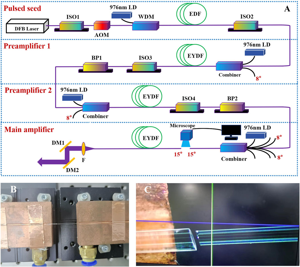
FIGURE 1. Structure of narrow-linewidth pulsed Er-doped fiber laser amplification. (A) Setup of the whole amplifier; (B) Photograph of the fiber butting; (C) Enlargement of the butt ends from microscope.
The measured average power curve of the high repetition rate EYDF multi-stage amplification system at different pulse durations is illustrated in Figure 2A. The average power declines as the pulse duration decreases under the same pump power due to a decrease in the proportion of the modulated signal light. A 16 W highest average power delivered from the last stage amplifier is realized at a 10 kHz repetition rate for 600 ns pulses when the launching pump power reaches 72 W, which corresponds to a 1.6 mJ pulse energy, 2.7 kW peak power, and about 21.2% slope efficiency. The optical-to-optical conversion efficiency of the entire fiber amplification system at 600 ns pulse duration is approximately 17.8%. Keeping the repetition rate unchanged, when the pulse duration declines to 308 ns, the average power drops to 12 W, calculating to a 1.2 mJ energy and 3.9 kW peak power. The SBS-free operation occurs at pulse durations of 600 and 308 ns by monitoring the reverse spectra through one of the pump input ends of the (6 + 1) × 1 combiner. Continue to decrease the pulse width to 148 ns, the SBS phenomenon has just appeared at the output power of 6.9 W. Thus, a 0.69 mJ output energy and a 4.9 kW peak power are realized, indicating that the SBS threshold power is about 4.9 kW. The 10 kHz pulse sequence is shown in Figure 2B, the time interval between adjacent pulse peaks is 100 µs. The optical spectrum of the signal beam at the highest power is collected through an optical spectrum analyzer (Yakogawa, AQ6370D) with a resolution of 0.02 nm, as illustrated in Figure 3. The signal peak corresponds to 1,551.15 nm with a SNR of about 36 dB, and there are no out-of-band ASE peaks around the 1,535 nm during the process of raising power. The inset represents the linear spectrum of the signal light at the 1,551.15 nm signal peak. The spectral half width is approximately 0.02 nm, constrained by spectrum analyzer resolution.
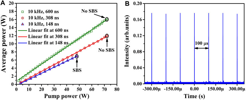
FIGURE 2. (A) Average power of Er-Yb co-doped multi-stage fiber amplification system; (B) Pulse sequence at 10 kHz.
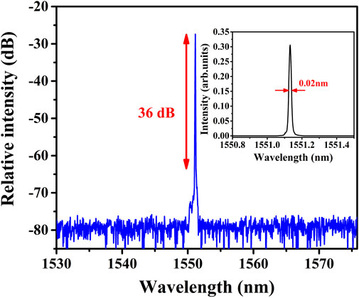
FIGURE 3. Signal spectra at the highest power. The inset is the linear spectrum of signal light at 1,551.1 nm.
When increasing average power to 6.9 W for a pulse duration of 148 ns at 10 kHz, the SBS effect is detected from the reverse spectrum, as displayed in Figure 4. It can be seen that the fundamental light wavelength and Stokes light wavelength emerge at 1,551.15 and 1,551.23 nm based on SBS effect. The corresponding frequency interval between the signal light and Stokes light is about 10 GHz, which is agreed with the Brillouin frequency shift of 1.55 µm laser in quartz fiber [25]. In addition, the onset of the SBS can be detected by the forward amplified pulse signal. The falling edge of the pulse begins to shake and becomes instable when SBS appears. A typical pulse profile at the onset of SBS is shown in the inset of Figure 4. In the experimental, the requirement for the power increase in the multi-stage amplifiers is the absence of the Stokes light wavelength at the reverse spectra and the pulse instability phenomenon.
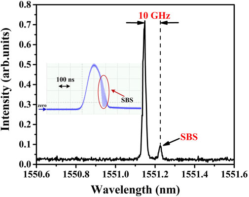
FIGURE 4. Reverse spectrum of the amplifier at the onset of SBS. The inset is temporal trace.
Pulse shaping technology for input electrical pulses of the AOM is crucial to compensate pulse steepening to boost pulse energy. Different input pulse shapes have different compensation capabilities. The influence of three electrical pulse shapes on the shapes of the output pulses is investigated under almost identical optical pulse half widths, as illustrated in Figure 5. The left of Figure 5 represents the input electrical pulse, and the right represents the amplified optical pulse. When the input pulse is a square wave with a full width of 370 ns, the rising time of amplified optical pulse is 47 ns, as displayed in Figure 5A. It is obvious that the leading edge of the output pulse experiences severe steepening, limiting the output energy boosting of the amplifier due to SBS caused by a high peak power. When the input pulse shape is a square-like wave with a full width of 474 ns and rising time of 270 ns, the rising time of the amplified optical pulse is 91 ns, as shown in Figure 5B, indicating that the phenomenon of pulse steepening has been alleviated. To further compensate for pulse steepening, a triangular-like wave with a slower rising edge for a full width of 400 ns is applied in input pulse, as illustrated in Figure 5C. The rising time of the amplified optical pulse is 122 ns. As a result, the pulse profile becomes symmetrical and pulse steepening is almost eliminated. For a given peak power, the laser pulses with slower rising edge and more symmetrical profile can achieve higher energy output.

FIGURE 5. Input electrical pulses (left) with different shapes and the corresponding amplified light pulses (right). (A) Input square wave; (B) Input square-like wave; (C) Input triangular-like wave.
Since the optical spectrum analyzer cannot meet the measurement demand for single-frequency light linewidth with MHz level, a heterodyne system that combines the CW DFB light and frequency-shifted amplified output light is constructed to characterize the half width of frequency spectrum of main amplifier. The beating signal recorded by a 1.5 µm photodetector (Thorlabs, DET08C/M) and a digital oscillator (Teledyne LeCroy, 813Zi-A). By applying a signal processing of fast Fourier transform (FFT) on the beating signal, a frequency-intensity spectrum is acquired, as shown in Figure 6. Therefore, at the highest average power, the linewidth of the single-frequency pulsed amplifier calculated by fitting the Lorentz function is about 1.02 MHz.
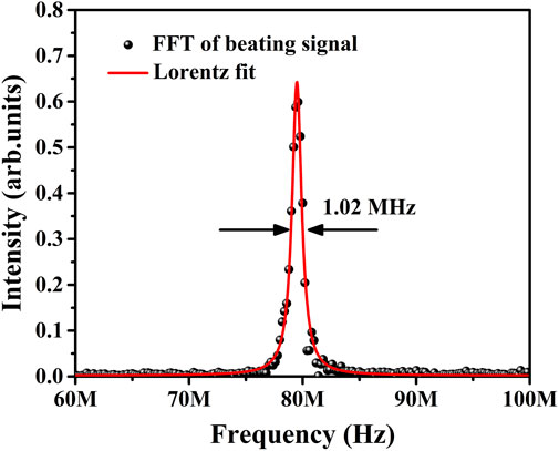
FIGURE 6. Frequency-intensity spectrum of the single-frequency pulsed light.
Table 1 summarizes the research progress of single-frequency EYDF MOPA system at 1.5 µm eye-safe wavelength. Obviously, the energy enhancement of 1.5 µm fiber amplifiers mainly relies on increasing the mode field area of active fibers. In particular, the MOPA system with high-gain and short-length phosphate glass fiber can also achieve high energy laser output [20]. In terms of the output characteristics of the MOPA system, relatively high average power and peak power at 10 kHz are realized in this work by using very-large-mode-area fibers.
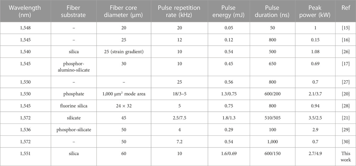
TABLE 1. Advances research of 1.5 μm single-frequency pulsed EYDF MOPA system.
In conclusion, we have implemented a 1.55 µm EYDF single-frequency multi-stage amplifier system, the main amplifier is composed of a very-large-mode-area fiber to suppress SBS. A highest average power of 16 W is achieved for a 600 ns pulse duration at 10 kHz, the corresponding energy, peak power, and slope efficiency are 1.6 mJ, 2.7 kW, and 21.2%, respectively. The peak power is scaled up to 4.9 kW for a pulse duration of 148 ns at the onset of SBS. The signal light is located at 1,551.15 nm with a SNR of about 36 dB, which is separated from the Stokes light by 10 GHz. Pulse shaping technology using a triangular-like wave with a slower rising edge is applied on the modulator to compensate the pulse steepening. The spectral half width retrieved from the beat frequency signal is approximately 1.02 MHz. This high average power, high peak power fiber MOPA system at 1.55 µm will be an excellent light source for laser lidar applications.
The raw data supporting the conclusion of this article will be made available by the authors, without undue reservation.
YW: Investigation, Writing–original draft. YL: Data curation, Writing–review and editing. DZ: Software, Writing–review and editing. CX: Visualization, Writing–review and editing. PL: Supervision, Validation, Writing–review and editing.
The author(s) declare financial support was received for the research, authorship, and/or publication of this article. This work was funded by the National Natural Science Foundation of China (NSFC) (62205008).
The authors declare that the research was conducted in the absence of any commercial or financial relationships that could be construed as a potential conflict of interest.
All claims expressed in this article are solely those of the authors and do not necessarily represent those of their affiliated organizations, or those of the publisher, the editors and the reviewers. Any product that may be evaluated in this article, or claim that may be made by its manufacturer, is not guaranteed or endorsed by the publisher.
The Supplementary Material for this article can be found online at: https://www.frontiersin.org/articles/10.3389/fphy.2023.1330573/full#supplementary-material
1. Canat G, Renard W, Lucas E, Lombard L, Le Gouët J, Durécu A, et al. Eyeshade high peak power pulsed fiber lasers limited by fiber nonlinearity. Opt Fiber Technol (2014) 20:678–87. doi:10.1016/j.yofte.2014.06.010
2. Kameyama S, Ando T, Asaka K, Hirano Y, Wadaka S. Compact all-fiber pulsed coherent Doppler lidar system for wind sensing. Appl Opt (2007) 46:1953–62. doi:10.1364/AO.46.001953
3. Philippov V, Sahu JK, Codemard C, Clarkson WA, Jang JN, Nilsson J, et al. All-fiber 1.15 mJ pulsed eye-safe optical source. Proc SPIE (2004) 5335:1–7. doi:10.1117/12.527451
4. Karlsson CJ, Olsson FÅA, Letalick D, Harris M. All-fiber multifunction continuous-wave coherent laser radar at 155 µm for range, speed, vibration, and wind measurements. Appl Opt (2000) 39:3716–26. doi:10.1364/AO.39.003716
5. Zhao Q, Wu Z, Zhang Z, Lin W, Li C, Guan X, et al. Stable actively Q-switched single-frequency fiber laser at 1.5 μm based on self-injecting polarization modulation. Opt Express (2018) 26:17000–8. doi:10.1364/OE.26.017000
6. Imaki M, Tanaka H, Hirosawa K, Yanagisawa T, Kameyama S. Demonstration of the 1.53-µm coherent DIAL for simultaneous profiling of water vapor density and wind speed. Opt Express (2020) 28:27078–96. doi:10.1364/OE.400331
7. Polynkin P, Polynkin A, Mansuripur M, Moloney J, Peyghambarian N. Single-frequency laser oscillator with watts-level output power at 1.5 μm by use of a twisted-mode technique. Opt Lett (2005) 30:2745–7. doi:10.1364/OL.30.002745
8. Zhang N, Li G, Qiao W, Xu R, Xuan H, Li T, et al. Investigations of the high-power, single-frequency, sub-microseconds, 1548-nm fiber laser based on the optical pulse modulation. J Lightwave Technol (2023) 41:4822–30. doi:10.1109/JLT.2023.3244867
9. Liao SK, Yong HL, Liu C, Shentu GL, Li DD, Lin J, et al. Long-distance free-space quantum key distribution in daylight towards inter-satellite communication. Nat Photon (2017) 11:509–13. doi:10.1038/NPHOTON.2017.116
10. Shun CM, Chan PW. Applications of an infrared Doppler lidar in detection of wind shear. J Atmos Ocean Tech (2008) 25:637–55. doi:10.1175/2007JTECHA1057.1
11. Henderson SW, Hannon SM. Advanced coherent lidar system for wind measurements. Proc SPIE (2005) 5887:108–17. doi:10.1117/12.620318
12. Zhang HM, Wu SH, Wang QC, Liu BY, Yin B, Zhai XC. Airport low-level wind shear lidar observation at Beijing capital international airport. Infrared Phys Techn (2019) 96:113–22. doi:10.1016/j.infrared.2018.07.033
13. Wu SH, Yin JP, Liu BY, Liu JT, Li RZ, Wang XT, et al. Characterization of turbulent wake of wind turbine by coherent Doppler lidar. Proc SPIE (2014) 9262:41–50. doi:10.1117/12.2069566
14. Inokuchi H, Akiyama T, Sasaki K. Flight demonstration of a long range onboard Doppler lidar. Proc 31st Congress Int Counc Aeronaut Sci (2018) 9:1–7.
15. Pearson GN, Eacock JR. Fiber-based coherent pulsed Doppler lidar for atmospheric monitoring. Proc SPIE (2002) 4484:51–7. doi:10.1117/12.452799
16. Bouteyre AD, Matthieu GC, Augere VB, Besson C, Goular D, Lombard L, et al. Pulsed 1.5-μm LIDAR for axial aircraft wake vortex detection based on high-brightness large-core fiber amplifier. IEEE J Sel Top Quant (2009) 15:441–50. doi:10.1109/JSTQE.2008.2010463
17. Lombard L, Bouteyre AD, Besson C, Augère B, Bourdon P, Durécu A, et al. Long range wind lidars based on novel high spectral brilliance all-fibered sources. Proc SPIE (2015) 9645:51–62. doi:10.1117/12.2197350
18. Wang X, Zhou P, Wang XL, Xiao H, Si L. 102 W monolithic single frequency Tm-doped fiber MOPA. Opt Express (2013) 21:32386–92. doi:10.1364/OE.21.032386
19. Shi W, Petersen EB, Leigh M, Zong J, Yao Z, Chavez-Pirson A, et al. High SBS threshold single-mode single-frequency monolithic pulsed fiber laser in the C-band. Opt Express (2009) 17:8237–45. doi:10.1364/OE.17.008237
20. Akbulut M, Kotov L, Wiersma K, Zong J, Li MH, Miller A, et al. An eye-safe, SBS-free coherent fiber laser LIDAR transmitter with millijoule energy and high average power. Photonics (2021) 8:15–7. doi:10.3390/photonics8010015
21. Lee W, Geng J, Jiang S, Yu AW. 1.8 mJ, 3.5 kW single-frequency optical pulses at 1572 nm generated from an all-fiber MOPA system. Opt Lett (2018) 43:2264–7. doi:10.1364/OL.43.002264
22. Vu KT, Malinowski A, Richardson DJ, Ghiringhelli F, Hickey LMB, Zervas MN. Adaptive pulse shape control in a diode-seeded nanosecond fiber MOPA system. Opt Express (2006) 14:10996–1001. doi:10.1364/oe.14.010996
23. Shi CD, Tian H, Fu SJ, Sheng Q, Shi Z, Jiang PH, et al. High-energy single-frequency pulsed fiber MOPA at 1064 nm based on a hybrid active-fiber. Opt Express (2022) 30:15575–82. doi:10.1364/oe.454703
24. Shi CD, Tian H, Shi W, Sheng Q, Zhang JX, Sun S, et al. High-power single-frequency narrow-linewidth nanosecond pulsed fiber laser based on triangle-shaped pulse. Proc SPIE (2021) 11665:116651B. doi:10.1117/12.2582898
25. Kobyakov A, Sauer M, Chowdhury D. Stimulated Brillouin scattering in optical fibers. Adv Opt Photon (2010) 2:1–59. doi:10.1364/aop.2.000001
26. Zhang X, Diao W, Liu Y, Liu J, Hou X, Chen W. Single-frequency polarized eye-safe all-fiber laser with peak power over kilowatt. Appl Phys B (2014) 115:123–7. doi:10.1007/s00340-013-5582-3
27. Akbulut M, Hwang J, Kimpel F, Gupta S, Verdun H. Pulsed coherent fiber lidar transceiver for aircraft in-flight turbulence and wake-vortex hazard detection. Proc SPIE (2011) 8037:80370R. doi:10.1117/12.883990
28. Canat G, Jetschke S, Unger S, Lombard L, Bourdon P, Kirchhof J, et al. Multifilament-core fibers for high energy pulse amplification at 15 μm with excellent beam quality. Opt Lett (2008) 33:2701–3. doi:10.1364/OL.33.002701
29. Philippov V, Codemard C, Jeong Y, Alegria C, Sahu JK, Nilsson J, et al. High-energy in-fiber pulse amplification for coherent lidar applications. Opt Lett (2004) 29:2590–2. doi:10.1364/OL.29.002590
Keywords: narrow linewidth, fiber amplifier, very-large-mode-area active fiber, high average power, pulse shaping
Citation: Wang Y, Li Y, Zhang D, Xiong C and Li P (2023) Pulse shaping, high average power narrow linewidth Er, Yb co-doped fiber amplifier. Front. Phys. 11:1330573. doi: 10.3389/fphy.2023.1330573
Received: 31 October 2023; Accepted: 16 November 2023;
Published: 28 November 2023.
Edited by:
Quan Sheng, Tianjin University, ChinaReviewed by:
Preeti Gupta, Leibniz Institute for Solid State and Materials Research Dresden (IFW Dresden), GermanyCopyright © 2023 Wang, Li, Zhang, Xiong and Li. This is an open-access article distributed under the terms of the Creative Commons Attribution License (CC BY). The use, distribution or reproduction in other forums is permitted, provided the original author(s) and the copyright owner(s) are credited and that the original publication in this journal is cited, in accordance with accepted academic practice. No use, distribution or reproduction is permitted which does not comply with these terms.
*Correspondence: Pingxue Li, cHhsaUBianV0LmVkdS5jbg==
Disclaimer: All claims expressed in this article are solely those of the authors and do not necessarily represent those of their affiliated organizations, or those of the publisher, the editors and the reviewers. Any product that may be evaluated in this article or claim that may be made by its manufacturer is not guaranteed or endorsed by the publisher.
Research integrity at Frontiers
Learn more about the work of our research integrity team to safeguard the quality of each article we publish.