 Xinyi Zhang
 Guoxing Lu1*
94% of researchers rate our articles as excellent or good
Learn more about the work of our research integrity team to safeguard the quality of each article we publish.
Find out more
ORIGINAL RESEARCH article
Front. Phys., 13 December 2023
Sec. Interdisciplinary Physics
Volume 11 - 2023 | https://doi.org/10.3389/fphy.2023.1304426
This article is part of the Research TopicOrigami-Inspired Metamaterials and MetastructuresView all 5 articles
In this study, the mechanical characteristics of the graded origami bellows were numerically investigated and experimentally validated. Two graded geometric parameters were considered: pre-folding angle (θ) and layer height (Le). The sensitivities of the deployment process and energy absorption efficiency of origami bellows to variations in θ and Le under quasi-static loading and dynamic loading were numerically investigated. Results show that the origami bellows with positive gradients exhibited progressive deployment process. More than one deformation mechanism was triggered during deployment, indicating a mixed non-rigid deployment mode. A large gradient of θ had a notable effect on the energy absorption efficiency. Both specific energy absorption (SEA) and mean tensile force (Pm) decreased as the gradient of θ increased. Although the gradient of Le was insensitive to the force response, the SEA decreased as the gradient of Le increased. The dynamic behavior of the graded models indicated that both the initial peak force and SEA were affected by the graded parameters. In general, the proposed graded origami bellows show a controllable deployment process and a stable force response under axial tension.
Thin-walled tubes, due to their exceptional mechanical characteristics, lightweight, long-stroke distance, and low cost, have been widely employed as energy absorption (EA) devices in many applications involving crushing in the field of aerospace, transportation, and automobiles [1].
In addition to the applications involving the thin-walled tubes under crushing, applications of thin-walled tubes under tension have been concerned as well. Bellows joints, regarded as a type of thin-walled tubes, are utilized to connect ends of pipelines to absorb the energy generated by the relative movement in pipelines [2, 3]. Other scenarios requiring resistance to tension can be found in applications such as safety ropes, arresting barricade, and aircraft carrier arresting cables [4, 5]. Hence, it is expected that thin-walled tubes can be employed as EA devices resisting tension.
Origami tubes with certain patterns, such as doubly pleated [4], Kresling [6], and Tachi–Miura patterns [7], have been demonstrated to exhibit deployable behavior [8], multi-stable behavior [9], and energy absorption behavior [10, 11]. For example, Zhang et al. [4] experimentally and numerically investigated the quasi-static axial deployment behavior and energy absorption performance of origami bellows under tension. They found that a smooth force response without excessive initial force, followed by a high mean tensile force in the models with reasonable designs, was obtained. Studies have shown that the deployment mode, which has a significant effect on the EA behavior of origami tubes, is mainly determined by their crease patterns. Origami tubes with Kresling and modified Miura patterns have been experimentally demonstrated to experience a non-rigid deployment process during axial loading by Reid et al [12]. This indicates that in such tubes, plastic deformation occurs more in material than in tubes that deploy rigidly; this greater deformation area enhances EA efficiency. Overall, origami bellows are a good candidature as an EA device under tension. However, the uniformity of the stacking layers of the abovementioned origami tubes leads to a limited number of application scenarios.
With growing requirements for lightweight construction and safety in thin-walled structures, a plethora of studies have recently proposed thin-walled tubes and metamaterials with graded material properties [13], wall thickness [14, 15], and structural geometries [16]. Among these graded parameters, those with the graded structural geometries have relatively low cost and high manufacturability compared with those with graded parent materials [17]. Graded tubes and metamaterials have been numerically and experimentally demonstrated to exhibit programmable mechanical properties, and as a result, energy efficiency is effectively improved. Studies have shown that graded tubes with reasonable designs have higher efficiency in EA under crushing when compared with the conventional uniform tube. These graded tubes were developed based on conventional square tubes and circular tubes [18–21].
Recently, origami tubes with graded geometric parameters under axial quasi-static loading have been demonstrated to have better energy absorption capacity than their uniform counterparts. As well as being affected by the material selected, mechanical characteristics of a tube depend mainly on its crease pattern. Investigations of origami tubes as EA devices with graded geometric parameters are numerically and experimentally conducted [16, 22, 23]. For instance, Waal et al. [24] proposed an origami-based graded honeycomb tube. The quasi-static axial crushing behavior of the graded honeycomb tube exhibited a progressive failure, resulting in a lower initial peak force and higher EA when compared with the counterpart re-entrant honeycomb. Ma et al. [23] investigated the EA performance of a hexagonal origami crash box with graded pre-folding angle and graded layer height under quasi-static axial loading. They concluded that introducing graded parameters effectively enhances energy absorption capacity. However, they are insensitive to the SEA of the crash box. Xie et al. [22] proposed the graded origami tube by considering three types of graded geometric parameters: the dihedral angle, the number of units, and the combinations of them. The numerical results regarding the axial crushing behavior of the graded tubes showed that various peak forces occurred at different deformation stages. By reasonably varying both dihedral angles and the number of units of tubes, these peak forces gradually increased, resulting in an graded mechanical behavior. However, the effects of gradient parameters on deployment and energy absorption behavior of origami tubes under tension have not been investigated yet.
In this paper, the mechanical characteristics in terms of deployment behavior and EA performance of graded origami bellows are investigated. The remainder of this paper is organized as follows: Section 2 presents the geometric design of uniform origami bellows and graded origami bellows. Section 3 provides the details about the fabrication process of prototype specimens, properties of annealed materials, and experimental results. Section 4 presents the finite element method and results. The details of effects of graded geometric parameters in terms of pre-folding angle and layer height on the deployment process and EA of origami bellows are provided in Section 5. Section 6 presents the conclusion.
The graded origami bellows were developed from uniform origami bellows with a hexagonal cross section. The geometry of the crease pattern of typical origami bellows is shown in Figure 1A, in which the dashed lines and solid lines represent valley folds and mountain folds, respectively. A single-folded layer and the corresponding top view are shown in Figures 1B, C, respectively. The geometry of the crease pattern of the origami bellows can be defined by four parameters: long horizontal mountain length a, short horizontal valley crease length b, oblique angle α, and unit width 2h. In addition, some parameters of the folded layer including pre-folding angle θ, spatial angle 2β, layer height Le, rotation angle φ, layer diameter D, and projection angle
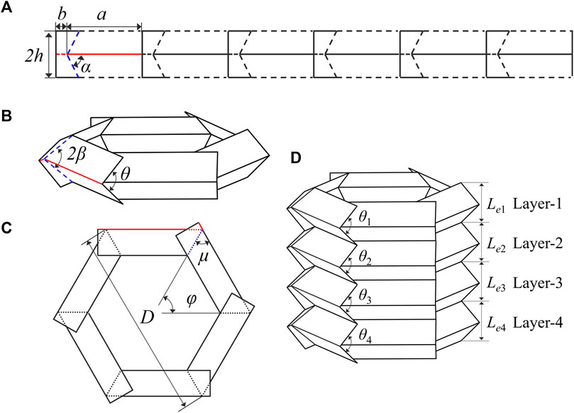
FIGURE 1. Geometry of the origami bellows: (A) one-layer crease pattern; (B) a single-layer origami bellows; (C) top view of (B); and (D) a four-layer graded origami bellows.
A completely closure bellows requires that
Moreover, the following equation should be satisfied to avoid interfering among units:
The geometry of a graded origami bellows with four layers is shown in Figure 1D. Here, we focus on two graded geometric parameters:
Then,
For the origami bellows with graded Le but identical θ,
where
A multi-layer graded origami bellows can be built by stacking several layers axially, provided that the side length of adjacent layers is identical. The experimental specimens and finite element models are named according to their layer stacking order from top to bottom. Moreover, gθ and gh denote graded θ and graded Le, respectively, and u denotes the uniform model. Thus, for instance, specimen named gθ-44-52-60-68-76 had a graded pre-folding angle, and its pre-folding angles in each layer from top to bottom were 44°, 52°, 60°, 68°, and 76°. Specific energy absorption (SEA), defined as the energy absorption per unit mass and mean tensile force (Pm), defined as the energy absorption divided by effective tensile displacement (
where
The displacement corresponding to the maximum value of f was considered the effective tensile displacement δe.
A parent material aluminum 1060 sheet with a wall thickness of 0.2 mm was adopted in this study to fabricate specimens. Uniform origami bellows u-60-60-60-60-60-60 and graded origami bellows gθ-44-52-60-68-76 were fabricated. It should be noted that due to experimental conditions and efficiency constraints, the uniform sample in this study comprises six layers, which differ from the graded sample. In our previous study [4], it has been demonstrated that the number of layers is insensitive to EA of uniform origami bellows. Additionally, the validations of experiments are mainly performed in this section. Therefore, the uniform sample with six layers is accepted. The dimensions of the uniform origami bellows are a = 38 mm, b = 3 mm, h = Le = 11 mm, and θ = 60°. These origami bellows consisted of six patterned pieces with six units in each. Six unfolded pieces were first obtained using waterjet cutting, and one example is shown in Figure 2B. However, the untreated parent material exhibited a low ductility that led to cracking along overlapping creases. Therefore, to enhance the ductility of the parent material, a complete annealing process, as shown in Figure 3, was conducted. The parent material was put into a furnace when its inside temperature was 50°C and then was annealed at 350°C for 100 min. Next, the annealed material was removed from the furnace when its inside temperature had cooled down to 50°C. Finally, the annealed material was cooled down to the room temperature of approximately 25°C. The heating and cooling rates of the furnace are set according to its own requirements. The sequential stamping method [26] was adopted in this study to gradually form required patterns on the pieces. Molds with different pre-folding angles decreasing from 140°, with an interval of 20°, to 60° were 3D-printed using acrylonitrile butadiene styrene (ABS) material. The patterned pieces were obtained using a total of five pairs of molds, each one stamped individually.
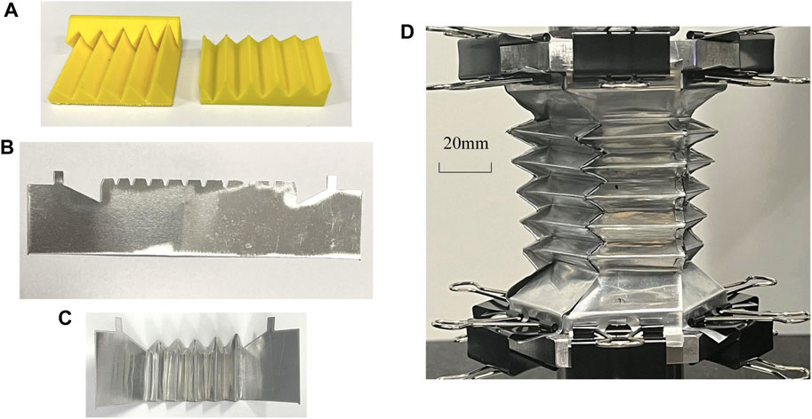
FIGURE 2. Fabrication of graded origami bellows: (A) female mold (left) and male mold (right) with desired graded pre-folding angles; (B) a water-jetting piece before stamping; (C) a patterned piece after stamping; and (D) a completed origami bellows with variation in the pre-folding angle.
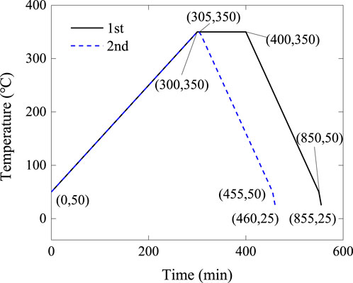
FIGURE 3. Annealing and cooling process for waterjet-cut pieces (following the first curve), patterned pieces (following the second curve), and dog-bone samples (following the first and then the second curves). The black solid line and blue dashed line refer to the first time annealing process and the second time annealing process, respectively.
The dimensions of graded origami bellows specimen gθ-44-52-60-68-76 are Le = 11 mm, a = 38 mm, θi values of each unit from top to bottom in a patterned piece are 44°, 52°, 60°, 68°, and 76°, and the corresponding hi values are 8.93, 9.83, 11, 12.55, and 14.68 mm. The patterns on one piece were formed unit by unit due to complicated geometry. The pre-folding angle of each pair of molds for units is as follows: unit molds with θ values of 140°, 120°, 100°, 80°, and 60° were used to form θ1 = 44°. For θ2 = 52° and θ3 = 60°, unit molds with θ values of 140°, 120°, 100°, and 80° were employed. For θ4 = 68°, unit molds with θ values of 140°, 120°, 100°, and 80° were employed. For θ5 = 76°, unit molds with θ values of 140°, 120°, and 100° were adopted. The final patterned pieces for the graded origami bellows were formed using the molds with desired θ in each unit, as shown in Figure 2A.
All patterned pieces were then placed into the furnace at 350°C for 5 min to release any residual stress. Gorilla clear glue with a shear strength of 1.24 N/mm2 was used in this study to glue the six patterned pieces together to obtain complete origami bellows. It should be noted that the shear strength of the glue may vary depending on the surfaces to which it is applied. In this instance, the shear strength of the bond between two aluminum 1060 surfaces was specifically measured under room temperature conditions of 25°C. The graded specimen is taken as an example, and its prototype is shown in Figure 2D. It should be noted that after removing residual stress, the toothed surfaces of each annealed patterned piece should be folded at 180° to be glued to adjacent pieces, leading to new residual stress around the folding area. These residual stresses are considered to have little effect on the mechanical behavior of origami bellows due to the negligible plastic deformation occurring in the overlapping folding areas.
A quasi-static tensile test was performed using the experimental setup. An example of the graded specimen setup is shown in Figure 2D. The specimen was glued between the fixtures. During the tensile tests, the top fixture moved upward at 2 mm min−1 to ensure a quasi-static loading condition. At the same time, the bottom fixture was fixed. The clips on the fixtures were not removed in order to protect the glued areas from debonding. A camera was used to capture and monitor the tensile and deployment process of the origami bellows.
Three dog-bone samples designed based on the standard ASEM E8/E8M-16a were adopted to measure the material properties of the annealed material. The dog-bone samples underwent the annealing and cooling process, as shown in Figure 3. The annealed dog-bone samples were then annealed at 350°C for 5 min for consistency with the overall annealing procedures for the patterned pieces. A universal testing machine with an electronic extensometer was used to conduct the tensile test. The loading speed of the test was 2 mm/min. A true stress–strain curve obtained from the tensile results is shown in Figure 4. The average material properties of the final annealed aluminum 1060 sheets were obtained as follows: Young’s modulus E = 16,677 MPa, density ρ = 2,700 kg/m3, Poisson’s ratio v = 0.3, yield stress σY = 32.5 MPa, and ultimate strength σu = 114.5 MPa.
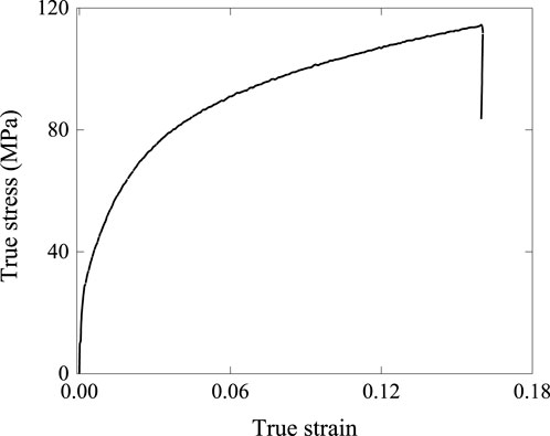
FIGURE 4. True stress–strain curve of annealed Al 1060 dog-bone samples after the twice-annealing process.
The sequences of the deformation process of the uniform specimen are provided in Figure 5A. Upon tension, a significant tensile displacement was observed at the transition parts between the specimen and fixtures. As displacement increased, the top and bottom layers primarily deployed, due to the motion of the transition parts. At the same time, the other layers experienced slight tensile displacements. The deformation process of units in the same layer was assumed to be uniform. With the increase in the tensile displacement, the deployment gradually spread to the middle layers until all layers had completely deployed, which indicates an asynchronous deployment mode. Since the original origami bellows had a rigid structure, non-rigid deformation involving both surface and crease bending was expected. However, from the local deformation around the fold vertexes of the uniform bellows, unclear traveling plastic hinge lines were formed, possibly influenced by imperfect manufacturing processes and the discontinuous surfaces.
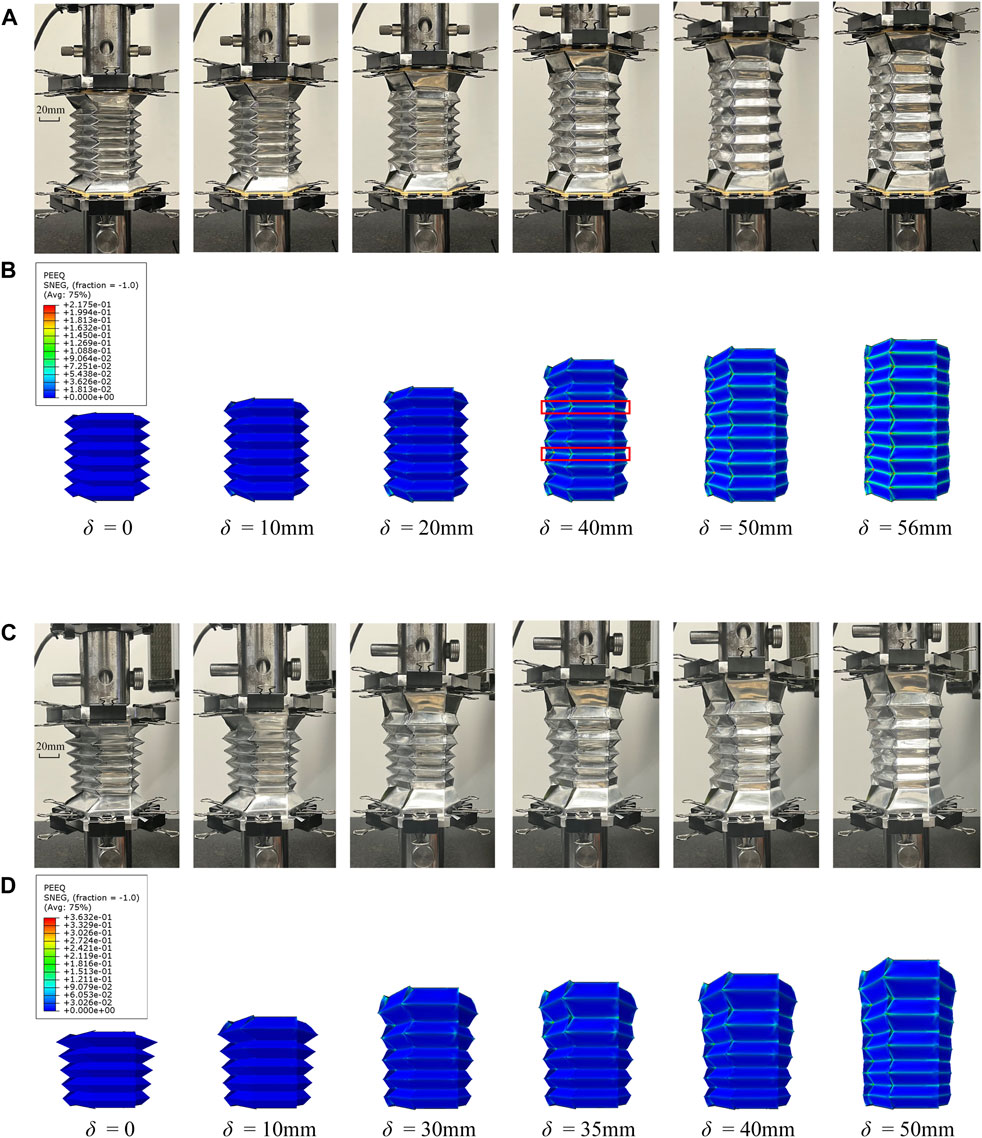
FIGURE 5. Sequences of the deformation process of specimens and the corresponding FEA models: experimental sequences of deformed configurations of (A) uniform origami bellows specimen and (B) graded origami bellows specimen. (C,D) Corresponding deformation process presented in terms of equivalent plastic strain (PEEQ) contours.
The axial force–displacement curves obtained from the experimental results show that a smooth response without excessive initial peak force was obtained, as illustrated in Figure 6A. The curve consists of three stages: an initial linear stage with force increasing during a small displacement, followed by a sloped stage characterized by a gradual increase in force, and then a complete deployment stage in which the force experiences a sharp increase. The energy efficiency versus tensile displacement curves is shown in Figure 6B. The effective tensile displacement of the uniform specimen was 47.5 mm. The corresponding Pm was calculated as 99.3 N and the SEA as 0.24 J·g−1.
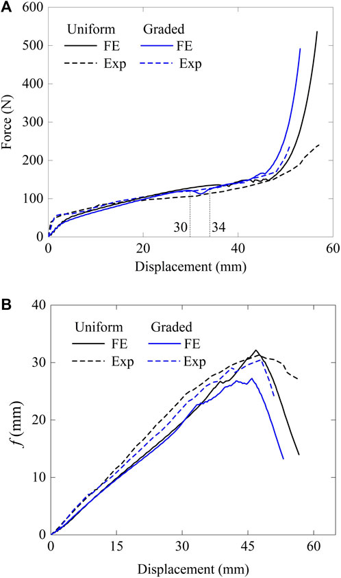
FIGURE 6. Comparison curves of experimental results and finite element results: (A) force versus displacement curves and (B) energy efficiency versus tensile displacement curves.
The sequences of the deployment process of the graded specimen are shown in Figure 5C. As in the deployment process of the uniform bellows, both the transition parts deployed first, resulting in the boundary layers being deployed. As the tensile displacement increased, the top layer, with the smallest pre-folding angle, experienced a significant deployment. As the tensile displacement increased, the bellows was gradually deployed from the layer with the smallest pre-folding angle to the layer with the largest pre-folding angle. In other words, an ordered deployment process progressively moved from the top layer to the bottom layer. The explanation for this is that layers with smaller pre-folding angles require less energy to deploy, and plastic deformation tends to be triggered at the lowest energy requirement. The experiment demonstrated that introducing a graded pre-folding angle into origami bellows effectively changes the deployment process of their layers.
The force–displacement curve for the graded specimen is shown in Figure 6A. The entire curve exhibits smoothness without excessive initial peak force. The curve for the uniform bellows is shown by the black dashed line. The two curves have the same shape until the displacement reaches approximately 20 mm. However, beyond this point, the reaction force of the graded specimen surpassed that of the uniform specimen. This phenomenon can be attributed to the gradual increase in the initial θi to more than 60° of the successive deploying layers in the graded specimen, while θ = 60° was identical in each layer in the uniform specimen. As demonstrated in the previous study [4], the tensile reaction force increases with the pre-folding angle. Therefore, during the layers deploying, the force response of the graded specimen became larger than that of the uniform specimen in the latter part of the curve.
The finite element model of origami bellows under axial quasi-static tension was built using the commercial software program Abaqus/Explicit 6.14-4. The nodes on the long horizontal edges of the top half of the top layer were given a uniform tensile displacement. The nodes on the long horizontal edges of the bottom half of the bottom layer were fixed. All the above nodes were constrained in rotational degrees of freedom. The bellows were meshed with the linear shell element S4R with a size of 0.8 mm. To avoid interfacing between overlapped surfaces during deployment, a general contact was defined under hard contact conditions. The friction coefficient was set to 0.3 [26]. To ensure a quasi-static loading condition, the ratio of artificial energy to internal energy was kept below 5% in all cases. The loading velocity was set to 0.3 m/s. The material properties of the finite element analysis (FEA) model were set to the parameters measured in the tensile tests of the dog-bone samples.
The sequences of the deployment process of the uniform origami bellows obtained from FEA are shown in Figure 5B. Influenced by the loading boundaries, the end layers mainly deployed, while the other layers experienced relative slight deformation. When tensile displacement δ increased to 20 mm, plastic deformation primarily occurred at the folding vertex of each unit due to incompatible geometry. As δ increased, the other layers deployed in a random order. At the same time, plastic strain was observed along the folding lines of the units in the deploying layer. The plastic deformation significantly formed between two adjacent layers due to the deployment of the connection area. For instance, at δ = 40 mm, the connection areas between the second and third layers and the fourth layer and fifth layers were undergoing deployment. A significant plastic strain was observed along the horizontal valley folding lines enclosed in red rectangles, as shown in Figure 5B. Moreover, it can be observed that the layers exhibited a non-rigid deployment mode characterized by crease and surface bending. At a displacement of 50 mm, all layers completely deployed. A comparison of the experimental and FEA results for the entire deployment process demonstrates good agreement.
The force–displacement curve of graded origami bellows as obtained from FEA is shown in Figure 6A. It can be found that the force response increased smoothly with a small fluctuation presented before dentification. The fluctuations were not found in the experimental results, approximately due to the discontinuous surface and imperfect fabrication. The effective tensile displacement of the uniform origami bellows in FEA was 46.8 mm. The corresponding mean tensile force was 101.8 N—this represents a 2.5% difference compared with the experimental result. Overall, there is good agreement between the FEA and experimental results of the uniform origami bellows under tension.
The equivalent plastic strain (PEEQ) contours of graded origami bellows are shown in Figure 5D. Unlike the uniform origami bellows, the graded origami bellows experienced an ordered deployment. In the beginning, upon axial tension, the boundary layers significantly deployed. As the displacement increased, the deployment displacement of the top layer became larger than that of the bottom layer due to larger h and smaller θ of the top layer. Meanwhile, as shown in Figure 6A, the force on the graded bellows was slightly lower than that on the uniform bellows at first (at δ = 0 mm–25.8 mm). As the displacement increased to 30 mm, the area between the top layer and the second layer began to deploy. The pre-folding angle of this area was 48° (which is less than the meanwhile onset deploying area in the uniform bellows), resulting in a drop in force along the curve (at δ = 32.5 mm). This phenomenon can be explained by the variation in pre-folding angles among the layers of the graded bellows. Afterwards, when δ increased from 34 to 45.9 mm, the pre-folding angles of the successively deploying areas in the graded bellows were larger than those in the uniform bellows, resulting in a greater force slope than that of the uniform bellows. When δ reached 50 mm, complete deployment was achieved. An illustration of the local deformation mechanism of deformed graded origami bellows is shown in Figure 7. The dashed and solid yellow lines represent the initial inclined creases and the formed traveling plastic hinge lines, respectively. A non-rigid deployment mode, characterized by gradually decreasing swapping areas of the traveling hinge lines from the top to the bottom, was generated. In the graded origami bellows described here, h of the layers gradually decreased from the top layer to the bottom layer, resulting in each layer having a different deformation mechanism. This significant observation demonstrated that the graded origami bellows exhibited a mixed non-rigid deployment mode. The mean tensile force obtained from the FEA was 99.3 N, which has an 8.8% difference compared to the experimental result.
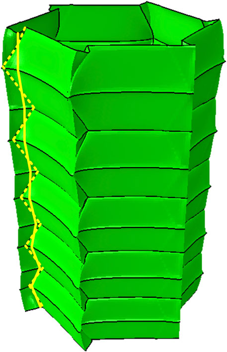
FIGURE 7. Illustration of the local deformation mechanism of the graded origami bellows, where the dashed yellow lines and the solid yellow lines refer to initial inclined creases and formed traveling plastic hinge lines, respectively.
In summary, the finite element model was validated by the corresponding experiments. Both experimental and FEA results show that introducing the graded geometric parameters can change the deployment process. However, it appears to have no significant effect on the EA performance.
A uniform origami bellows with θ of 60° was used as the basis to create graded origami bellows with variations in θ gradients of 2°, 4°, 6°, and 8°. The height of each layer was 11 mm as that in the uniform bellows. The average θ was 60° in all models. In each model, θ increased uniformly from the top layer to the bottom layer, indicating a positive gradient. The illustrations of the geometries of the representative graded models are shown in Figure 8. Numerical results have demonstrated that the values of a and b are insensitive to the mechanical response of the origami bellows, as detailed in the Supplementary Material. Therefore, the effect of the lengths of a and b can be reasonably ignored.
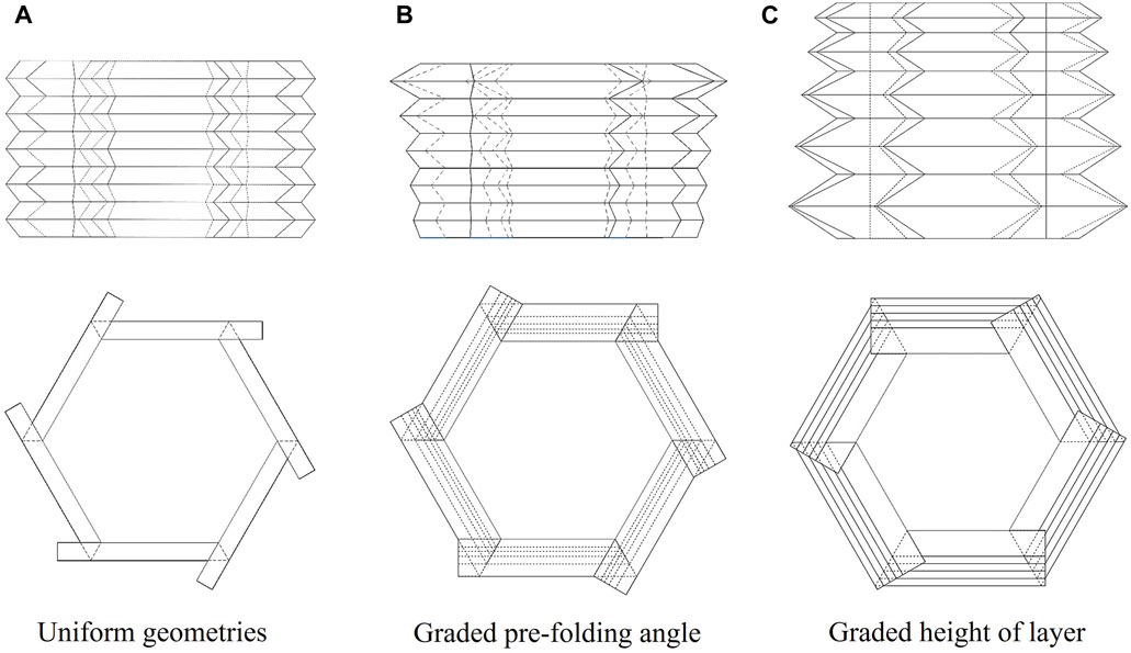
FIGURE 8. Illustrations of main views (in top) and top views (in bottom) of representative graded models. The dashed lines represent invisible areas. (A) Uniform model u-90-90-90-90-90, (B) model with graded pre-folding angle gθ-50-70-90-110-130, and (C) model with graded height of layer gh-7-9-11-13-15.
Dimensionless displacement was used by dividing the tensile displacement by its effective displacement to ensure the same tensile scale for the curves, facilitating comparisons. The force versus dimensionless displacement curves of graded origami bellows with average θ of 60° are shown in Figure 9A. It can be observed that within a narrow range of variation in θ among layers, all curves have a similar shape. When δ/δe changed from 0 to 0.64, force response slightly decreased as the gradient increased. There was a little difference among the curves when δ/δe fell within the range of 0.64–1. During this stage, the adjacent area with different θ values deployed. The uniform origami bellows exhibited some uniform fluctuations due to their layers having the same pre-folding angle θ. For the graded origami bellows, an increase in the variation in θ led to an increased amplification of these fluctuations. The graded origami bellows exhibited the largest initial fluctuation because the smallest θ was deployed. As the displacement increased, the fluctuation amplitude gradually decreased, resulting in a smoother curve. The geometric parameters and EA values of the different models are summarized in Table 1. It is evident that the EA performance shows minimal sensitivity to θ within the small gradient range of 2°–8°.
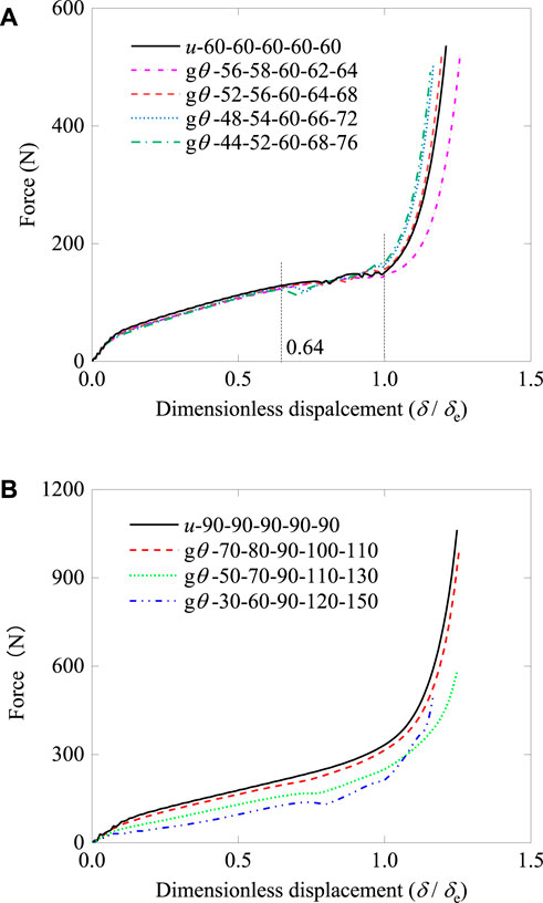
FIGURE 9. Force versus dimensionless displacement curves. Force–displacement curves of graded and uniform origami bellows. (A) Average pre-folding angles θ = 60° and (B) θ = 90°.
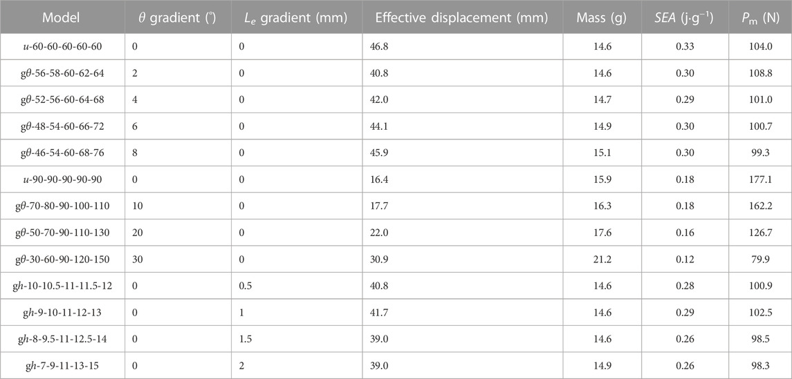
TABLE 1. Energy absorption results of uniform and graded origami bellows under quasi-static loading.
To extensively understand the effects graded θ, graded origami bellows with large variations in θ of 10°, 20°, and 30° were created based on u-90-90-90-90-90. In the uniform model, θ = 90°, h = 7.78 mm, a = 52.7 mm, and b = 10.3 mm. Figures 11A, B show the PEEQ contours of the axial tensile process of u-90-90-90-90-90 and gθ-50-70-90-110-130, respectively. It indicates that a positive variation in θ leads to a sequential deployment that starts from the top layer and progress downward to the bottom layer. In contrast, the uniform origami bellows exhibited a uniform deployment process. In both instances, plastic deformation initially manifested at the folding vertices and eventually propagated along their creases.
Figure 9B shows the force–displacement curves of origami bellows with a wide range of θ gradients. It can be observed that, as the gradient increased, the response force decreased. This phenomenon arises from the fact that the first layer of the bellows with the highest gradient had the smallest pre-folding angle; hence, the top layer deploys first leading to the lowest response force. Although the initial pre-folding angles in the other layers are large, the energy efficiency can only be improved within a small displacement. The EA results of the graded models that were based on u-90-90-90-90-90 are listed in Table 1. It can be observed that both SEA and mean force decreased as the gradient increased. Moreover, the amplitude of this decrease became more pronounced as the gradient increased.
Additionally, the EA behavior of origami bellows with a graded pre-folding angle under dynamic loading at 10 m/s was numerically investigated. Model u-90-90-90-90-90 is still taken as the basis line. Strain rate effect is neglected in the simulations. The comparison results of the force–displacement curves of different graded models are shown in Figure 10. The plateau force decreases as the gradient and all cases exhibit a large initial peak force due to the effect of dynamic loading. To evaluate the tensile force efficiency (TFE) of graded origami bellows under dynamic, the TFE is calculated as follows:
where Pmax is the initial peak force of the force response. The calculation results of energy absorption are listed in Table 2. It can be found that introducing graded pre-folding angle effectively increases TFE. However, similar to EA under quasi-static behavior, SEA decreases as the gradient increases.
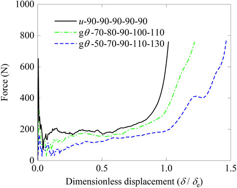
FIGURE 10. Force versus dimensionless displacement curves of origami bellows with a graded pre-folding angle under dynamic loading at 10 m/s.
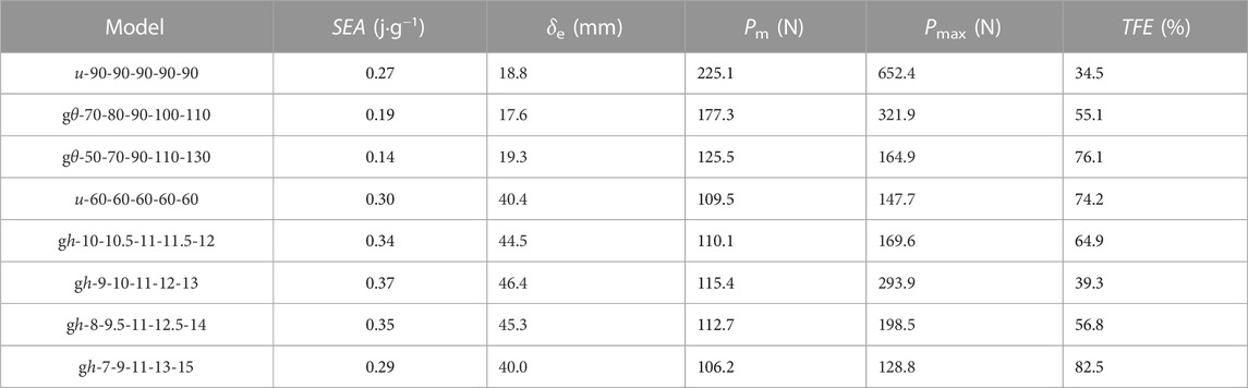
TABLE 2. Energy absorption results of uniform and graded origami bellows under dynamic loading at 10 m/s.
It can be found that the energy absorbed by traveling plastic hinges and toroidal surfaces is relevant to unit width 2h. Therefore, graded layer height is expected to contribute significantly to the EA of the origami bellows. Here, the EA capacity of origami bellows with graded layer height is numerically investigated. Model u-60-60-60-60-60 with h = 11 mm was used as the base model to create other four graded models. The positive gradients in Le varied from 0.5 to 2 mm, while bellow height L remained constant at 55 mm and θ at 60°. Taking gh-8-9.5-11-13.5-15 as an example, its PEEQ contours, shown in Figure 11C, presented a sequential deployment from the bottom to the top. This was because the layer height decreased from the bottom to the top, leading to an increase in the force required for deformation.
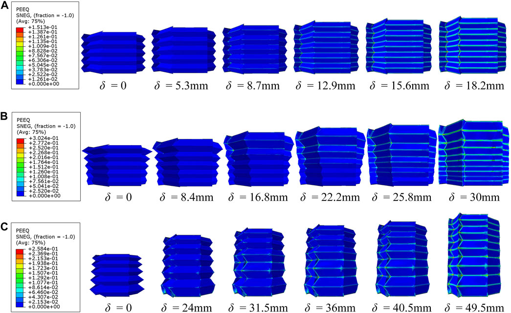
FIGURE 11. Sequences of deformation process in terms of equivalent plastic strain (PEEQ) contours of (A) uniform model u-90-90-90-90-90, (B) graded model gθ-50-70-90-110-130 with variations in pre-folding angle, and (C) graded model gh-8-9.5-11-12.5-14 with variations in layer height.
The force–tensile displacement curves of these models shown in Figure 12 presented similar shapes. The force gradually increased when displacement was between 0 and 28.5 mm, without generating excessive peak force. Between tensile displacement of 28.5 and 42.9 mm, fluctuations formed due to the deployment of each adjacent area. As displacement continued to increase, force increased sharply, indicating complete deployment of all layers. All models showed approximately identical total EA due to having the same area under the curves. However, the EA results listed in Table 1 indicate that the SEA of the models with graded Le was smaller than that of the uniform model. This can be explained by models with larger layer height gradients having greater mass, resulting in lower SEA. Moreover, the comparison among all models with graded layer heights showed that SEA decreased as the gradient increased.
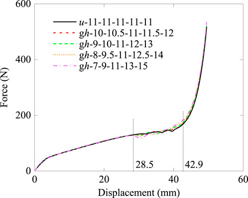
FIGURE 12. Force versus displacement curves of the origami bellows with the graded height of layers under quasi-static loading.
The mechanical response of the origami bellows with graded layer heights under dynamic loading at 10 m/s was investigated as well. Figure 13 shows the force against displacement curves from the finite element simulations. It can be observed that the origami bellows with different gradients in Le show different initial peak forces. Additionally, force responses at the early deformation stage and the latter half of the plateaus force are different. The EA calculation results are summarized in Table 2. With an increase in the gradient value, both Pm and SEA initially rise and then decline. However, TFE exhibits a reverse trend, decreasing and then increasing with the gradient overall. Compared with quasi-static behavior, the graded layer height proves to be more responsive to the dynamic behavior of origami bellows.
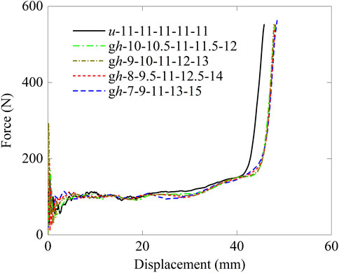
FIGURE 13. Force versus displacement curves of the origami bellow with the graded height of layers under dynamic loading at 10 m/s.
In this paper, origami bellows with positive gradients in pre-folding angle and layer height were designed. The axial tensile behavior and EA behaviors of the graded origami bellows under quasi-static loading and dynamic loading were numerically investigated. Three conclusions are summarized as follows.
First, both experimental results and numerical results showed that the force–tensile displacement curves of graded origami bellows exhibited a smooth curve without excessive initial peak force. A good agreement between experimental and numerical results is obtained.
Second, introducing the positive gradients of θ and Le into the origami bellows influenced the deployment behavior of the bellows. A progressive deployment process characterized by deploying from the top layer to the bottom layer was observed. On the contrary, for the uniform origami bellows, the random and uniform processes were triggered by different geometric parameters.
Finally, a small range of variation from 2° to 8° in θ has been found, showing a slight effect on the reaction force and EA efficiency. A large variation within the range from 10° to 30° leads to a decrease in both Pm and SEA, provided that the initial Le is identical. Although the gradient of Le being insensitive to the force–displacement curve, SEA decreased as the gradient value increased. The dynamic response of the graded models revealed that the graded parameters influenced both the initial peak force and SEA.
Further modifications of graded models will be designed to explore the effects of the graded parameters on the deployment behavior and EA capacity of the origami bellows under tension.
The original contributions presented in the study are included in the article/Supplementary Material; further inquiries can be directed to the corresponding author.
XZ: conceptualization, data curation, formal analysis, investigation, methodology, software, and writing–original draft. GL: conceptualization, methodology, supervision, and writing–review and editing. SW: project administration, resources, supervision, and writing–review and editing. YD: funding acquisition, project administration, supervision, and writing–review and editing.
The author(s) declare that financial support was received for the research, authorship, and/or publication of this article. This research was financially supported by the Australian Department of Industry Innovation and Science under the Automotive Engineering Graduate Program (AEGP) (AEGP000019) for YD and Australian Research Council Discovery Grant (DP210103323) for GL.
The authors declare that the research was conducted in the absence of any commercial or financial relationships that could be construed as a potential conflict of interest.
All claims expressed in this article are solely those of the authors and do not necessarily represent those of their affiliated organizations, or those of the publisher, the editors, and the reviewers. Any product that may be evaluated in this article, or claim that may be made by its manufacturer, is not guaranteed or endorsed by the publisher.
The Supplementary Material for this article can be found online at: https://www.frontiersin.org/articles/10.3389/fphy.2023.1304426/full#supplementary-material
1. Lu G, Yu TX. Energy absorption of structures and materials. Cambridge, UK: Woodhead Publishing Limited (2003).
2. Xiang XM, Lu G, Li ZX, Lv Y. Finite element analysis and experimental study on a bellows joint. Eng Struct (2017) 151:584–98. doi:10.1016/j.engstruct.2017.08.034
3. Cai J, Xu Y, Feng J. Geometric analysis of a foldable barrel vault with origami. J Mech Des (2013) 135(11). doi:10.1115/1.4025369
4. Zhang X, Wang S, Durandet Y, Palanisamy S, Lu G. Energy absorption behavior of origami bellows under tension. Int J Mech Sci (2023) 246:108143. doi:10.1016/j.ijmecsci.2023.108143
5. Ishida S, Ahmad NB, Oka K. Numerical analysis on rigidity of cylindrical honeycomb cores under radial loads. J Adv Simulation Sci Eng (2020) 7(1):189–200. doi:10.15748/jasse.7.189
6. Cai J, Zhang Y, Xu Y, Zhou Y, Feng J. The foldability of cylindrical foldable structures based on rigid origami. J Mech Des (2016) 138(3). doi:10.1115/1.4032194
7. Miura K, Tachi T. Synthesis of rigid-foldable cylindrical polyhedral. Symmetry Art Sci (2010) 204–13.
8. Li M, Zhou Z, Hao B, Yu C, Chen Y, Ma J. Design and deformation analysis of an inflatable metallic cylinder based on the Kresling origami pattern. Thin-walled Struct (2023) 188:110859. doi:10.1016/j.tws.2023.110859
9. Cai J, Deng X, Zhou Y, Feng J, Tu Y. Bistable behavior of the cylindrical origami structure with Kresling pattern. J Mech Des (2015) 137(6):061406. doi:10.1115/1.4030158
10. Ma J, Hou D, Chen Y, You Z. Quasi-static axial crushing of thin-walled tubes with a kite-shape rigid origami pattern: numerical simulation. Thin-Walled Structures (2016) 100:38–47. doi:10.1016/j.tws.2015.11.023
11. Song J, Chen Y, Lu G. Axial crushing of thin-walled structures with origami patterns. Thin-walled Struct (2012) 54:65–71. doi:10.1016/j.tws.2012.02.007
12. Reid A, Lechenault F, Rica S, Adda-Bedia M. Geometry and design of origami bellows with tunable response. Phys Rev E (2017) 95(1):013002. doi:10.1103/physreve.95.013002
13. Karbasian H, Tekkaya AE. A review on hot stamping. J Mater Process Technol (2010) 210(15):2103–18. doi:10.1016/j.jmatprotec.2010.07.019
14. Sun G, Tian X, Fang J, Xu F, Li G, Huang X. Dynamical bending analysis and optimization design for functionally graded thickness (FGT) tube. Int J Impact Eng (2015) 78:128–37. doi:10.1016/j.ijimpeng.2014.12.007
15. Zhang X, Wen Z, Zhang H. Axial crushing and optimal design of square tubes with graded thickness. Thin-walled Struct (2014) 84:263–74. doi:10.1016/j.tws.2014.07.004
16. De Waal L, Lu G, Zhang J, You Z. Dynamic behaviour of graded origami honeycomb. Int J Impact Eng (2021) 157:103976. doi:10.1016/j.ijimpeng.2021.103976
17. Xu F, Zhang X, Zhang H. A review on functionally graded structures and materials for energy absorption. Eng Structures (2018) 171:309–25. doi:10.1016/j.engstruct.2018.05.094
18. Nagel GM, Thambiratnam DP. A numerical study on the impact response and energy absorption of tapered thin-walled tubes. Int J Mech Sci (2004) 46(2):201–16. doi:10.1016/j.ijmecsci.2004.03.006
19. Hou S, Han X, Sun G, Long S, Li W, Yang X, et al. Multiobjective optimization for tapered circular tubes. Thin-walled Struct (2011) 49(7):855–63. doi:10.1016/j.tws.2011.02.010
20. Avalle M, Chiandussi G. Optimisation of a vehicle energy absorbing steel component with experimental validation. Int J Impact Eng (2007) 34(4):843–58. doi:10.1016/j.ijimpeng.2006.02.001
21. Baykasoglu C, Cetin MT. Energy absorption of circular aluminium tubes with functionally graded thickness under axial impact loading. Int J Crashworthiness (2015) 20(1):95–106. doi:10.1080/13588265.2014.982269
22. Xie R, Hou D, Ma J, Chen Y, You Z. Geometrically graded origami tubes. In: Proceedings of ASME 2016 International Design Engineering Technical Conferences and Computers and Information in Engineering Conference. Volume 5B: 40th Mechanisms and Robotics Conference; 21-24 August 2016; Charlotte, North Carolina, USA. ASME (2016). V05BT07A010.
23. Ma J, Dai H, Shi M, Yuan L, Chen Y, You Z. Quasi-static axial crushing of hexagonal origami crash boxes as energy absorption devices. Mech Sci (2019) 10(1):133–43. doi:10.5194/ms-10-133-2019
24. De Waal L, You Z. Graded origami honeycomb tube for energy absorption. In: Proceedings of ASME 2019 International Design Engineering Technical Conferences and Computers and Information in Engineering Conference. Volume 5B: 43rd Mechanisms and Robotics Conference; 18-21 August 2019; Anaheim, California, USA. ASME (2019). V05BT07A040.
25. Yuan H, Pikul JH, Sung CR. Programmable 3-D surfaces using origami tessellations. In: Proceedings of the 7th International Meeting on Origami in Science, Mathematics and Education; 4-7 September 2018; Oxford, UK. St Albans, UK: Tarquin (2018). p. 893–906.
Keywords: graded origami bellows, quasi-static behavior, dynamic behavior, energy absorption, non-rigid deployment, axial tension
Citation: Zhang X, Lu G, Wang S and Durandet Y (2023) Mechanical characteristics of graded origami bellows under axial tension. Front. Phys. 11:1304426. doi: 10.3389/fphy.2023.1304426
Received: 29 September 2023; Accepted: 23 November 2023;
Published: 13 December 2023.
Edited by:
Yang Li, Wuhan University, ChinaReviewed by:
Zhejian Li, Guangzhou University, ChinaCopyright © 2023 Zhang, Lu, Wang and Durandet. This is an open-access article distributed under the terms of the Creative Commons Attribution License (CC BY). The use, distribution or reproduction in other forums is permitted, provided the original author(s) and the copyright owner(s) are credited and that the original publication in this journal is cited, in accordance with accepted academic practice. No use, distribution or reproduction is permitted which does not comply with these terms.
*Correspondence: Guoxing Lu, Z2x1QHN3aW4uZWR1LmF1
Disclaimer: All claims expressed in this article are solely those of the authors and do not necessarily represent those of their affiliated organizations, or those of the publisher, the editors and the reviewers. Any product that may be evaluated in this article or claim that may be made by its manufacturer is not guaranteed or endorsed by the publisher.
Research integrity at Frontiers
Learn more about the work of our research integrity team to safeguard the quality of each article we publish.