- 1Wenzhou Institute, Hangzhou Dianzi University, Wenzhou, China
- 2School of Electronics and Information, Hangzhou Dianzi University, Hangzhou, China
- 3School of Electrical and Electronic Engineering, The University of Western Australia, Crawley, WA, Australia
Traditional binary combinational logic circuits are generally obtained by cascading multiple basic logic gate circuits, using more components and complicated wiring. In contrast to the binary logic circuit design in this method, ternary combinational logic circuit implementation is more complicated. In this paper, a ternary circuit design method that does not require cascading basic ternary logic gates is proposed based on a tri-valued memristor, which can directly realize specific logic functions through a series connection of memristors. The ternary encoder, ternary decoder, ternary comparator, and ternary data selector are implemented by this method, and the effectiveness of the circuits is verified by LTspice simulations.
1 Introduction
Traditional digital systems are built on binary numbers, where only two levels are considered, namely, “0” and “1.” However, with the rapid development of modern information technology and the increasing integration of digital systems, interconnection limitations have become one of the main challenges in implementing the binary logic in the nano-scale circuit design [1]. Interconnect lines cause increased latency, noise, and power consumption in the system. In multi-valued logic (MVL), a single signal line carries more information, which can effectively reduce the number of interconnecting lines and solve the interconnection problem in binary digital systems [2]. After the calculation demonstration in [3], it can be seen that when the base is e, the complexity and cost of the multi-valued system are the lowest and 3 is the integer closest to e. Therefore, compared with binary logic, ternary logic has significant advantages. In 1840, the British mathematician and inventor Thomas Fowler first proposed the concept of a ternary computer, but the relevant details have long been lost. Glusker studied and sorted it, and elaborated the relevant concepts of ternary logic and ternary computer in [4] in 2005. Although the same number of binary signals are easier to process than ternary signals, ternary signals can carry more information, which can effectively improve the efficiency of information transmission and storage. Therefore, compared with binary logic, ternary logic has stronger information processing capabilities and can solve some complex and cumbersome problems in binary logic.
Memristor is a nonlinear nano-component with many excellent properties such as stable resistive performance, low power consumption, and compatibility with traditional CMOS technology. In particular, the circuit realized by the memristor can have both operation and storage functions, so a memristor is considered to be a strong competitor to replace traditional silicon chips and continue Moore’s law. Compared with traditional digital logic circuits using CMOS, memristor-based digital logic circuits can effectively reduce the area and power consumption of the circuit [5–9]. At present, there are still few research studies on ternary logic based on the memristor, and most of them need to realize corresponding functions by memristors combined with complementary metal–oxide semiconductor (CMOS). In 2016, Khalid designed a basic ternary logic gate using a circuit structure similar to MRL (hybrid CMOS/memristive logic gate) [10], which reduced the number of components. In 2020, Zhang designed flexible logic circuits based on spintronic memristors and CMOS switches to implement basic unbalanced logic gates with non-volatility, good load capacity, and constant voltage input and output without signal degradation [11]. In the same year, Wang designed ternary AND gates, OR gates, NOT gates, and maximum and minimum circuits by utilizing the compatibility of memristors and CMOS, and achieved an order of magnitude improvement in data density; the switching speed of the memristor is reduced by a factor of about 13 [12]. However, the aforementioned circuits require CMOS devices to work together, which leads to more circuit area and power consumption, as well as more complex operation steps and the amount of running power supply. In addition, some of the ternary logic circuits are designed by the memristor combined with the carbon nanotube field-effect transistor (CNTFET). In 2018, basic ternary logic gates, ternary decoders, 2-bit adders, and standard ternary inverters based on memristors and CNTFETs were proposed [13,14]. In 2019, Soliman proposed a systematic method for constructing a 2-bit ternary function based on the concept of the memristive threshold logic [15]. A 2-bit ternary adder and multiplier are implemented using VTEAM memristors and Stanford CNTFET transistor models. In the same year, Chen fabricated a memristor device based on nano-columnar crystalline ZnO thin films and used it to realize a complete set of ternary logic and a ternary multiplier unit [16]. Nevertheless, the logic variables of these circuits are voltage, and the memristors are only used as a computing unit rather than a storage unit. Therefore, these designs have the problems of signal degradation and loss of power-off information.
Due to the lack of actual ternary components corresponding to ternary logic, the promotion of ternary logic in practical applications is not smooth. Based on the asymmetric piecewise linear memristive mathematical model [17] extended by Chua on the basis of the voltage-controlled odd-symmetric piecewise linear memristive model in 2015, Wang’s team first proposed the concept of the tri-valued memristor in 2019, obtained tri-valued and multi-valued memristor models on this asymmetric piecewise linear memristor model, and realized a new chaotic circuit based on the tri-valued memristor model [12]. In [18], a method for realizing ternary basic logic gates based on tri-valued memristors is proposed. The designed logic gates do not need to use other CMOS devices, and the power consumption of the circuit is lower. As a multi-valued memristor, the tri-valued memristor can exhibit three different resistance states without using any additional devices to represent “0,” “1,” and “2” in ternary logic, and the application of tri-valued memristors to digital logic circuits can further reduce circuit power consumption and the circuit area, which improves the storage density. In addition, a tri-valued memristor provides a non-traditional computing architecture, that is, combines information storage and processing, which create favorable conditions for the realization of ternary logic circuits.
The rest of this paper is as follows: Section 2 explains the process of constructing a voltage-controlled tri-valued memristor, and the threshold characteristics and pinched hysteresis loop of this memristor are analyzed. Section 3 proposes a tri-value circuit design method using the resistance state of the memristor to represent the logic value. This method does not require cascading the basic tri-value logic gates and allows specific logic functions to be implemented directly through series and parallel connections of the memristors. Concretely, the ternary combinational logic gate circuits based on a tri-valued memristor include a ternary encoder, a decoder, a comparator, and a data selector, and the designed circuit is verified by LTspice. Section 4 gives the summary of this paper.
2 A tri-valued memristor built by two common binary memristors
Ternary logic is a multivalued logic with three different logic states. The tri-valued memristor is a crude element which exhibits three different states (resistances) matching “0,” “1,” and “2” in the ternary logic without using any additional devices. In this paper, the resistances of the tri-valued memristor are used as the logic state variables, where RH, RM, and RL are used to represent logics “0,” “1,” and “2”. The voltage threshold tri-valued memristor explained in this paper and its threshold characteristics are introduced as follows.
2.1 Modeling of a tri-valued memristor
In 2021, Wang proposed a voltage threshold tri-valued memristor model that has the characteristics of simple structure and clear principle. The model parameters can be modified according to the actual application requirements [18]. In [19], an implementation method of connecting two tri-valued memristors in series and parallel to obtain a multi-valued memristor was proposed. As a result, a voltage-controlled tri-valued memristor model is obtained in this paper by connecting two voltage-controlled binary memristors in parallel, and the resulting tri-valued memristor model is used to design ternary combinational logic circuits. It is also proved that the tri-valued memristor model in [18] can be realized using the binary memristor through the circuit structure.
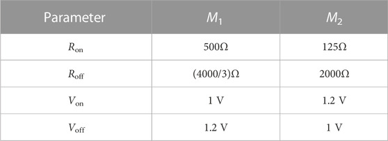
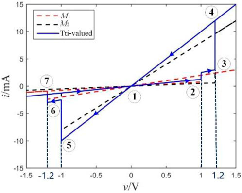
In 2015, Knowm Inc. company designed and produced a voltage threshold binary memristor called the Knowm memristor. In this paper, by modifying the expression of G(v) of the Knowm memristor from G(v) = v/Ron +(1- v)/Roff to G(v) = IF (v < 0.5, 1/Roff, 1/Ron), a better threshold binary memristor model is obtained. Based on this model, we obtained a tri-valued memristor by putting two Knowm memristors in parallel, as shown in Figure 1, with parameters shown in Table 1. The v-i curves of two single memristors (M1 and M2) and the tri-valued memristor with three distinct resistance states are shown in Figure 2.
2.2 Characteristics of the tri-valued memristor
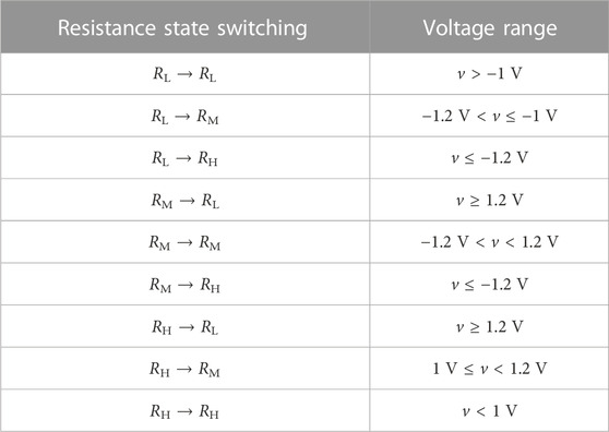
The tri-valued memristor mentioned previously has voltage threshold characteristics, and its two threshold voltages are vth1 = 1 V and vth2 = 1.2 V, respectively. RL, RM, and RH correspond to three different resistance states of the model. According to the characteristics of the tri-valued memristor, voltages with different amplitudes (applied to the positive electrode of the memristor) will be used to initialize the memristor and implement the update of the memristor resistance value in the subsequent logic gate design. Specifically, when the voltage v ≥ 1.2 V, the memristor switches from any resistance state to RL. When 1 V ≤ v < 1.2 V, if the resistance state of the memristor is RH at this time, it will switch to RM; otherwise, it will remain unchanged. When -1 V < v < 1 V, the memristor will continue to maintain its original state. When −1.2 V < v ≤ −1 V, if the resistance state of the memristor is RL at this time, it will switch to RM; otherwise, it will not change. When v ≤ −1.2 V, the memristor switches from any resistance state to RH. Table 2 summarizes the voltage range required for the resistance state switching of the tri-valued memristor. The symbol “→” indicates that the resistance state on the left side is switched to that on the right side of the symbol.
In order to verify the threshold characteristics of the tri-valued memristor model, the voltage signals v = t and v = -t are applied to the memristor models with initial states of RH and RL, respectively, and the LTspice simulation results, as shown in Figure 3, are obtained, which indicate that the resistance switching process of the memristor is consistent with Table 2, proving that the tri-valued memristor built exhibit the threshold characteristics.
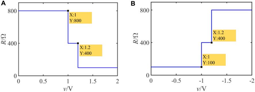
FIGURE 3. Relationship between the input voltage and the resistance of the tri-valued memristor; (A) the initial resistance is RH, and the input voltage is v = t; (B) the initial resistance value is RL, and the input voltage is v = -t.
2.3 Analysis of the pinched hysteresis loop of the tri-valued memristor
Figure 2 shows the trajectory of the pinched hysteresis loop obtained by applying the voltage v = 2sin (2πt) to the tri-valued memristor. The starting point of the pinched hysteresis loop, as shown in Figure 2, is ①; at this time, the resistances of M1 and M2 are both Roff, so the state of the tri-valued memristor at point ① is the initial state RH. Before reaching point ②, the voltage value across the memristor will not exceed the threshold voltage 1V, so the state of the memristor will not change. When point ② is reached, since the input voltage exceeds the threshold voltage 1V, it exceeds the threshold voltage Von of M1, and the resistance of M1 is switched to Ron, while the resistance of M2 remains unchanged. At this time, the resistance of the tri-valued memristor is set to RM.
At point ③, the voltage across the memristor reaches the threshold voltage of 1.2 V; at this time, the threshold voltages Von of M1 and M2 are exceeded at the same time, and the resistances of M1 and M2 are both switched to Ron; the resistance of the tri-valued memristor is set to RL. On the trajectory before reaching point ④, the voltage continues to increase, but the resistance of the tri-valued memristor will remain at RL. Along with the applied voltage decrease, from points ④ to ⑤, although the threshold voltage 1 V is crossed at this stage, the state of the memristor will not change because the resistance of the tri-valued memristor is RL during this period. When point ⑤ is reached, the voltage across the memristor reaches the threshold voltage −1 V, it exceeds the threshold voltage Voff of M2, and the resistance of M2 is switched to Roff, while the resistance of M1 remains unchanged, making the tri-valued memristor set to RM again. As the input voltage further decreases, reaching point ⑥, the voltage across the memristor exceeds the threshold voltage −1.2 V; at this time, the threshold voltages Voff of M1 and M2 are exceeded at the same time, and the resistances of M1 and M2 are both switched to Roff, making the tri-valued memristor set to RH again. Then, the input voltage reaches peak point ⑦ and begins to increase, during which the resistance of the tri-valued memristor will not change until it returns to the initial point ① to start the next cycle.
Overall, the pinched hysteresis loop of the tri-valued memristor model shows the characteristics that the resistance decreases with the increase in the forward voltage, and the resistance increases with the increase in the negative voltage. It is worth noting that the change law of the resistance value of this tri-valued memristor model is consistent with the change law of the resistance value shown by the HP memristor. So this tri-valued memristor model can be used to research on the application of multivalued memristors manufactured in the method of an HP memristor.
3 Ternary combination logic gates design
In this section, a series of ternary combinational logic circuits with memristor resistance as the logic state variable will be proposed. Specifically, it includes a ternary encoder, ternary decoder, ternary comparator, and ternary data selector, and the effectiveness of the designed ternary combinational logic gate will be verified by LTspice simulation.
3.1 Ternary encoder
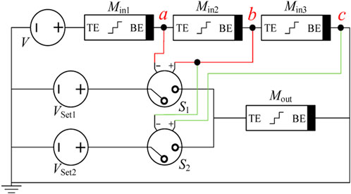
In the traditional binary or multivalued encoder, the circuit structure of the encoder is composed of cascaded basic logic gates, and the circuit structure is relatively complex. In this paper, a ternary encoder circuit based on the tri-valued memristor is proposed, which does not require cascading basic ternary logic gates. The circuit consists of three input memristors, one output memristor, and a corresponding number of voltage-controlled switches, and can realize the function of converting three channels of binary signals into one channel of ternary signals. The truth table of the designed 3-line–1-line ternary encoder is shown in Table 3, where X0, X1, and X2 are input signals, and Y is the output signal.
Figure 4 shows the circuit structure of a 3-line to 1-line ternary encoder based on tri-valued memristors. Among them, Min1, Min2, and Min3 are input memristors, Mout is the output memristor, and the initial resistance value of Mout is RH. The magnitudes of the output voltages of the DC voltage sources Vset1 and Vset2 are 1.1 and 1.3 V, respectively, which are used to complete the operations of setting “1” and setting “2”to Mout. S1 and S2 are voltage-controlled switches, which are turned on when the applied control voltages Vba and Vcb across Min2 and Min3 exceed their threshold voltages. After evaluation, the threshold voltages of S1 and S2 are set to satisfy that only one of these two switches is turned on or none of the switches is turned on (the output memristor maintains the initial value) under different inputs to realize the encoding function of the ternary encoder.
The operation of the encoder is driven by an excitation voltage source V, and its working process can be divided into two stages: the first stage is the initial stage where V outputs initial voltage VInit, which is used to measure the initial resistance state of each memristor. The second stage is the running stage, and in this stage, V will output running voltage VRun to complete the encoding operation. The initial voltage VInit must meet two conditions to complete the operation of measuring the initial state of the memristor: the first condition is to ensure that the voltage division of each input memristor does not exceed the threshold voltages vth1 and vth2 of the memristor when VInit is input. Otherwise, the resistance state of the input memristor will be changed; The second condition is that when VInit is input, the divided voltages Vba and Vcb on Min2 and Min3 would not exceed the threshold voltages of S1 and S2; otherwise, the resistance of the output memristor will change in the initial stage, which will cause the encoding result not correct under the running voltage VRun. Here, the only demand on VRun is to ensure that the voltage division of each input memristor does not exceed the threshold voltages vth1 and vth2 of the memristor when VRun works as an input. Based on the aforementioned rules, the initial voltage VInit and the operating voltage VRun of the ternary encoder are determined as 1.5 and 1.2 V, respectively. The operation stage of the 3-line–1-line ternary encoder designed in this paper can be divided into the following three situations:
(1) When the input logic is “100,” namely, Min1 = 400Ω, Min2 = 800Ω, and Min3 = 800Ω, according to the input voltage division calculation, Vba = Vcb = −0.48 V can be obtained. In the circuit, switches S1 and S2 need not be turned on at the same time to ensure the output logic “0,” so the threshold voltages of switches S1 and S2 must be greater than −0.48 V.
(2) When the input logic is “010,” namely, Min1 = 800Ω, Min2 = 400Ω, and Min3 = 800Ω, Vba = −0.24V and Vcb = −0.48 V can be produced at this moment based on the input voltage division computation. To assure the output logic “1,” switches S1 must be switched on and S2 need to turn off, so the threshold voltage of switches S1 must be less than −0.24 V and S2 must be more than −0.48 V.
(3) When the input logic is “001,” namely, Min1 = 800Ω, Min2 = 800Ω, and Min3 = 400Ω, the corresponding output logic should be “2.” In this case, the input voltage yields Vba = −0.48V and Vcb = −0.24 V, so the switch S1 need to be turned off and S2 must be switched on, which force the threshold voltage of switches S1 must be greater than −0.48 V and S2 must be less than −0.24 V.
Through the aforementioned analysis, it can be obtained that the range of the threshold voltages of S1 and S2 should be between −0.48, and −0.24 V to complete the function of the encoding circuit, so −0.3 V is chosen as the threshold voltages of both S1 and S2 at the end.
The ternary encoder circuit is built using LTspice, and the simulation results are shown in Figure 5. It can be observed that when the inputs are “100,” “010,” and “001”, the logic values of the output memristor are “0,” “1,” and “2,” which is consistent with the truth table of the ternary encoder, which proves the rationality of the designed ternary encoder circuit.

FIGURE 5. LTspice simulation results of the ternary encoder: (A) input as (1,0,0), (B) input as (0,1,0), and (C) input as (0,0,1).
3.2 Ternary decoder
Decoding is the reverse operation of encoding, and the function of the ternary decoder is to convert one ternary signal into three binary signals. Table 4 shows the truth table of the ternary decoder, where X represents the input of the ternary decoder, and Y0, Y1, and Y2 represent the outputs of the ternary decoder. It is worth noting that the valid logic values output by Y0, Y1, and Y2 can be either logic “1” or logic “2” according to actual needs, and in this paper, we take logic “1” as an example to design the ternary decoder.
Figure 6 shows the 1-line to 3-line decoder circuit based on tri-valued memristors and voltage-controlled switches. The resistance state of the memristor Min is used to represent the logic value of the input variable X. The initial resistance values of Mout1, Mout2, and Mout3 are all RH, which represent the logic values of the output variables Y0, Y1, and Y2, respectively. The voltage source Vset1 outputs 1.1 V to set each of the output memristor as logic “1.” The auxiliary resistor R is a key component in the circuit, and it helps realize more voltage division cases in the circuit. Without this resistor, the negative pole of Min would be grounded directly so that the voltage source V will be applied directly to Min. During the resistance state of Min changing, the divided voltage on it will always be equal to the power voltage V, which means the three input conditions cannot be distinguished, resulting in the inability to complete the decoding function. The value of R needs to be between the high resistance value and the low resistance value of the tri-valued memristor; in this part, R is selected as 400Ω. Similar to the 3–1 encoder circuit, the ternary decoder work in two stages, which are the initial stage with V=VInit = 0.5 V and running stage V = VRun = 1.2 V, respectively.
In the decoder design, if only one voltage-controlled switch is connected to each output memristor in the circuit, there is no guarantee that only one branch of each output is selected through. For example, each output memristor is connected to only one voltage-controlled switch, whose control voltage is the voltage across Min. In Case 1, when Min = RL, the switch with the smallest threshold voltage will be turned on. In Case 2, when Min = RM, the switch with the minimum and middle threshold voltages will be both turned on. In Case 3, when the resistance value of Min is the maximum value, that is, Min = RH, all three switches will be turned on, which do not guarantee that only one switch is turned on at each case. Therefore, in this design, we connect two voltage-controlled switches to each output memristor to ensure that under different input conditions, only one output memristor is connected to the voltage source Vset1 so that the corresponding output memristor can be set to RM.
In Figure 6, the control voltage of switches S1, S3, and S5 is the divided voltage Vbc on the resistor R. The control voltages of S2, S4, and S6 are the divided voltage Vab on the memristor Min. In the ternary decoder circuit design process, an operating voltage is first selected; then, by analyzing the voltage division under different inputs, the threshold voltage of switches S1–S6 is set to meet the command above as 0.3, 0.7, 0.5, 0.5, 0.9, and 0.2 V, respectively.
According to the specific resistance state of Min, the circuit operation stage of the ternary decoder can be summarized into the following three situations under the threshold voltage of switches S1–S6 set previously:
(1) When the input is logic “0,” that is, Min = 800Ω, at this time, Vbc = 0.4V and Vab = 0.8V, all of the switches S1, S2, S4, and S6 are turned on, and S3 and S5 are turned off, so only the output memristor Mout1 is set to 400Ω. The other two output memristors remain in their initial status. The logic gate output is “100.”
(2) When the input is logic “1,” Min = 400Ω. Vbc = Vab = 0.6 V. Switches S1, S3, S4, and S6 are all on, S3 and S5 are turned off, and only the output memristor Mout2 can be set to 400Ω. So the output of the logic gate is “010.”
(3) When the input is logic “2,” that is, Min = 100Ω, then Vbc = 0.96V and Vab = 0.24 V. Switches S1, S3, S5, and S6 are all on, and S2 and S4 are turned off, while the output memristor Mout3 is set to 400Ω; the other memristors will not change, so we obtain the outputs of the logic gate as “001.”
Similarly, the ternary decoder is simulated and verified using SPICE, as shown in Figure 7. When the inputs are “0,” “1,” and “2”, the corresponding outputs are “100,” “010,” and “001,” respectively. The function of converting one ternary signal into three binary signals is realized, which confirms the effectiveness of the designed 1-line–3-line ternary decoder circuit.

FIGURE 7. LTspice simulation results of the ternary decoder, (A) input “0,” (B) input “1,” and (C) input “2.”
3.3 Ternary comparator
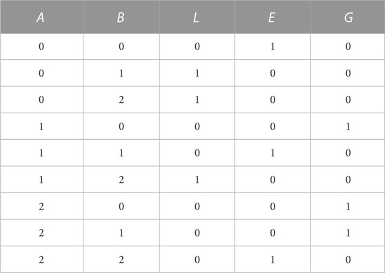
In digital logic circuits, it is often necessary to compare the magnitude of two numbers, and the circuit that completes this logic function is called a numerical comparator. For a one-bit ternary comparator, its input is two ternary numbers, and the output is the result of the comparison of the two numbers. The truth table of the one-bit ternary comparator is shown in Table 5, where A and B are the two input ternary numbers, and L, E, and G represent the three output binary numbers. L, E and G are valid when output logic “1,” representing A < B, A = B, and A > B, respectively.
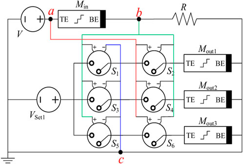
As shown in Figure 8, the one-bit ternary comparator consists of two input memristors, three output memristors, two voltage sources, and six voltage-controlled switches. Input variables A and B are represented by the resistances of Min1 and Min2, and the resistances of Mout1, Mout2, and Mout3 are used to represent variables L, E, and G. The initial resistances of Mout1, Mout2, and Mout3 are all RH. Similar to the decoder circuit, each output memristor in the circuit is connected with two switches to ensure that only one output memristor is connected to the voltage source Vset1 during the operation phase of the circuit. The two output voltages VInit and VRun of the voltage source V are 0.5V and 1 V, respectively, and Vset1 outputs 1.1 V for the operation of “1.”
In Figure 8, the control voltages of switches S1, S3, and S5 are Vbc across Min2, and Vab cross Min1 is used to control S2, S4, and S6. The threshold voltages of S1–S6 are 0.1, 0.6, 0.4, 0.4, 0.6, and 0.1 V, respectively. According to the specific logic states of Min1 and Min2, the specific operation of the ternary comparator in the running phase can be summarized as follows:
(1) If A < B, there are three cases of input resistances of Min1 and Min2, namely, (800Ω, 400Ω), (800Ω, 100Ω), and (400Ω, 100Ω). The divided voltages Vab and Vbc of Min1 and Min2 are (0.67 V, 0.33 V), (0.89 V, 0.11 V), and (0.8 V, 0.2 V). In the aforementioned three cases, all the switches S1, S2, S4, and S6 are turned on, and S3 and S5 are turned off. Therefore, only the output memristor Mout1 is set to 400Ω. The resistance of the other two output memristors remains unchanged, and the ternary comparator output is “100.”
(2) If A = B, the input resistances of Min1 and Min2 are the same, that is, (800Ω, 800Ω), (400Ω, 400Ω), and (100Ω, 100Ω). If Vab = Vbc = 0.5 V, at this time, switches S1, S3, S4, and S6 are all on, and S2 and S5 are turned off. Thus, only Mout2 is set to 400Ω, and the corresponding logic gate output is “010.”
(3) If A > B, there are also three cases of input resistance of Min1 and Min2, namely, (400Ω, 800Ω), (100Ω, 800Ω), and (100Ω, 400Ω). Vab and Vbc are (0.33 V, 0.67 V), (0.11 V, 0.89 V), and (0.2 V, 0.8 V). Switches S1, S3, S5, and S6 are all on, and S2 and S4 are turned off, which corresponds to the output memristor of Mout3, which is set to 400Ω; Mout1 and Mout2 remain RH. At this point, the output of the logic gate is “001.”
Figure 9 shows the LTspice simulation results of the ternary comparator. When the logic value of Min1 is less than that of Min2, Mout1, which is corresponding to the variable “L,” is set to logic “1.” Similarly, when the logic value of Min1 is equal to that of Min2, Mout2 corresponding to the variable “E” will output “1.” When the logic value represented by Min1 is greater than Min2, the output memristor Mout3, which represents the variable G, outputs the effective resistance value “1.” The simulation results are consistent with the truth table of the ternary comparator, which verifies the effectiveness of the designed one-bit ternary comparator circuit.
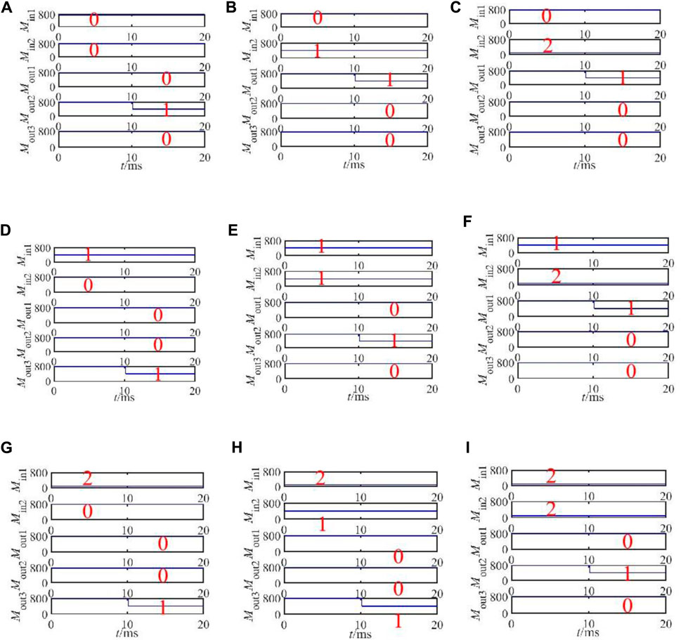
FIGURE 9. LTspice simulation results of the ternary comparator: (A) input as (0, 0), (B) input as (0, 1), (C) input as (0, 2), (D) input as (1, 0), (E) input as (1, 1), (F) input as (1, 2), (G) input as (2, 0), (H) input as (2, 1), and (I) input as (2, 2)
3.4 Ternary data selector
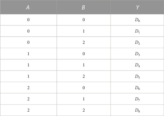
In the process of digital signal transmission, sometimes, it is necessary to select one from a group of data, and then, a logic circuit called data selector or multiplexer is used. The traditional binary data selector can select one data from four data through two address signals, while the ternary data selector based on the tri-valued memristor can select one output from nine data through two address signals. The truth table of the 9-out-of-1 ternary data selector is shown in Table 6, where A and B are two address signals, and Y outputs the data selected by the address signal.
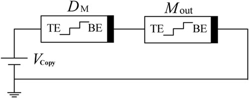
Before designing the ternary data selector circuit, a ternary copy gate needs to be introduced, whose function is to copy the information from the data memristor to the output memristor. The circuit structure is shown in Figure 10, which consists of an operating voltage source V, a data memristor DM, and an output memristor Mout. Among them, V outputs the operating voltage Vcopy, and the initial resistance of Mout is RH. According to the different input logic, it can be divided into the following three cases:
(1) If DM = 800Ω and the logic is “0,” the voltage of Mout should be less than 1 V to ensure Mout remain its initial resistance, which demand the divided voltage of Mout meets (800/1600)*Vcopy <1V, that is, Vcopy<2 V.
(2) If DM = 400Ω and the logic is “1,” to ensure Mout change from RH to RM, the divided voltage of Mout should be between 1 V and 1.2 V, so the divided voltage of Mout should satisfy the condition of ‘1 V< (800/1200)*Vcopy<1.2 V’, that is, 1.5 V ≤ Vcopy<1.8 V.
(3) If DM = 100Ω and the logic is “2,” Mout need to change from RH to RL, which needs to meet the condition of Vcopy≥1.35 V.
Combining the three aforementioned situations, the operating voltage of the ternary copy gate circuit must satisfy 1.5 V ≤ Vcopy<1.8 V. So we choose 1.6 V as the operating voltage of the copy gate, and the specific voltage division between the data memristor and the output memristor is shown in Table 7.

TABLE 7. Specific voltage division of each memristors in the calculation stage of the ternary copy gate.
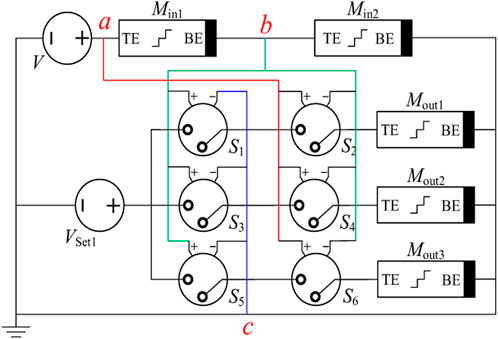
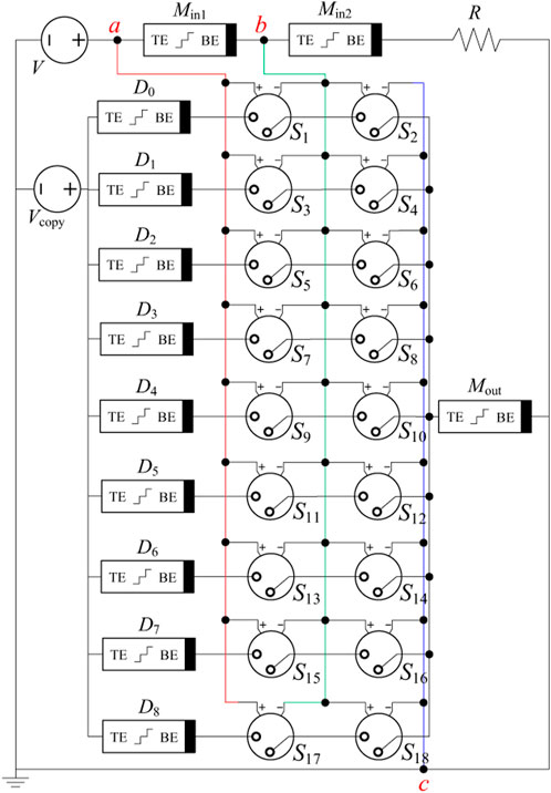
The circuit structure of the 9-out-of-1 ternary data selector based on tri-valued memristors is shown in Figure 11, where the input memristors Min1 and Min2 store two address signals A and B, and the data memristors D0–D8 store, respectively, nine channels of known ternary data. Mout outputs the data Di (i = 0, 1, 2,
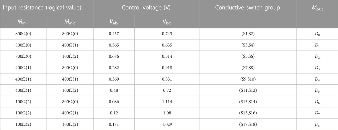
For convenience, switches S1–S18 are divided into nine groups. Each group is called a switch group, which is expressed as (S1, S2) ∼ (S17, S18), and each switch group is turned on only when two switches in the switch group are turned on at the same time. The threshold voltages of S1–S18 are set to 0.4, 0.73, 0.5, 0.6,0.6, 0.5, 0.2, 0.9, 0.3, 0.8, 0.47, 0.7, 0.05, 1.1, 0.1, 1.05, 0.15, and 1 V. Table 8 lists the situation of conductive switch groups and the output of Mout under different inputs of the 9-out-of-1 ternary data selector. According to the specific logic states of Min1 and Min2, the specific operation of the ternary data selector in the running phase can be summarized as follows. In this paper, the input logic “00” and “01” are taken as examples for detailed analysis. The analysis process of other inputs is the same, and the description will not be repeated here.
(1) The input logic is “00,” that is, Min1 = 800Ω and Min2 = 800Ω. Vab = 0.457V and Vbc = 0.743 V can be obtained by voltage division calculation. At this time, only S1 and S2 will be closed at the same time among the nine switch groups. Then, memristors D0 and Mout are connected in series for the copy operation, and the logic gate outputs the data stored in D0.
(2) The input logic is “01,” that is, Min1 = 800Ω, Min2 = 400Ω, Vab = 0.565V, and Vbc = 0.635 V. Only S3 and S4 are turned on at the same time among the nine switch groups. So the memristor pair D1 and Mout will be connected in series for the copy operation, and the logic gate outputs the data stored in D1.
The 9-out-of-1 ternary data selector is simulated using LTspice software, in which the data memristors D0–D8 store nine channels of ternary signals, and its resistance value and corresponding logic value are D0 = 800Ω (“0”), D1 = 400Ω (“1”), D2 = 100Ω (“2”), D3 = 800Ω (“0”), D4 = 400Ω (“1”), D5 = 100Ω (“2”), D6 = 100Ω (“2”), D7 = 400Ω (“1”), and D8 = 800Ω (“0”). The simulation results under different combinations of address signals are shown in Figure 12, which shows the data selection results of the 9-out-of-1 ternary data selector. The resistance values of Min1 and Min2 are the input address signals, and the resistance value of Mout is the output signal. When the inputs are “00,” “01,” “02,” “10,” “11,” “12,” “20,” “21,” and “22,” the ternary signals stored in D0, D1, D2, D3, D4, D5, D6, D7, and D8 are outputs, which are consistent with the output of the ternary data selector in Table 6, and verify the effectiveness of the designed ternary data selector circuit.
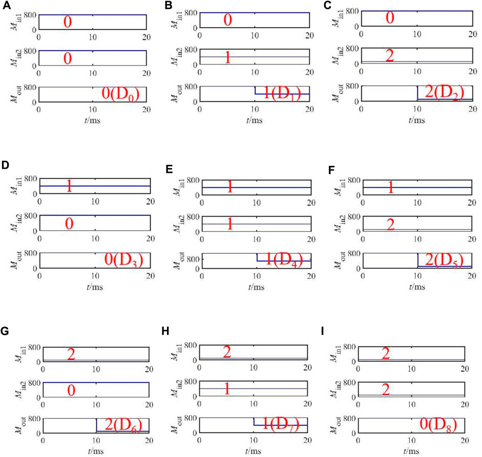
FIGURE 12. LTspice simulation result of the ternary data selector: (A) input as (0, 0), (B) input as (0, 1), (C) input as (0, 2), (D) input as (1, 0), (E) input as (1, 1), (F) input as (1, 2), (G) input as (2, 0), (H) input as (2, 1), and (I) input as (2, 2).
4 Conclusion
This paper presents a design method of the ternary combinational logic gate circuit based on a tri-valued memristor and realizes the ternary encoder, ternary decoder, ternary comparator, and ternary data selector with the resistance of the tri-valued memristor as the logic state variable. First, a voltage threshold tri-valued memristor is introduced, and the threshold characteristics of the tri-valued memristor are analyzed in detail. Second, using the tri-valued memristor, a series of complex combinational logic circuits with the resistance of the memristor as the logic state variable are designed, respectively, and the implementation principle of each gate is analyzed in detail. Finally, the effectiveness of the designed combinational logic gate circuits is verified by LTspice circuit simulation. Compared with the existing binary or ternary combinational logic gate circuits, the ternary combinational logic gate circuit based on the tri-valued memristor proposed in this paper does not need to be realized by cascading basic logic gates and can be realized only by a small number of tri-valued memristors and voltage-controlled switches. In addition, the logic gate designed by this method can not only perform logic operations but also store logic values.
Data availability statement
The original contributions presented in the study are included in the article/Supplementary Material; further inquiries can be directed to the corresponding author.
Author contributions
X-JL: validation, writing–review and editing, methodology, and writing–review and editing. X-YW: writing–review and editing, data curation, conceptualization, funding acquisition, investigation, methodology, project administration, and supervision. PL: writing–review and editing, data curation, and investigation. HI: visualization, and writing–review and editing. Z-QC: visualization, and writing–review and editing.
Funding
The author(s) declare financial support was received for the research, authorship, and/or publication of this article. This work was supported by the National Natural Science Foundation of China (Grant No. 61871429), the Natural Science Foundation of Zhejiang Province, China (Grant No. LY18F010012), and the Project of Ministry of Science and Technology of China (Grant No. D20011).
Conflict of interest
The authors declare that the research was conducted in the absence of any commercial or financial relationships that could be construed as a potential conflict of interest.
Publisher’s note
All claims expressed in this article are solely those of the authors and do not necessarily represent those of their affiliated organizations, or those of the publisher, the editors, and the reviewers. Any product that may be evaluated in this article, or claim that may be made by its manufacturer, is not guaranteed or endorsed by the publisher.
References
1. Hamedani SG, Moaiyeri MH. Impacts of process and temperature variations on the crosstalk effects in sub-10 nm multilayer graphene nanoribbon interconnects. IEEE Trans Device Mater Reliability (2019) 19(4):630–41. doi:10.1109/TDMR.2019.2937789
2. Khezeli MR, Moaiyeri MH, Jalali A. Analysis of crosstalk effects for multiwalled carbon nanotube bundle interconnects in ternary logic and comparison with Cu interconnects. IEEE Trans Nanotechnology (2016) 16(1):107–17. doi:10.1109/TNANO.2016.2633460
3. Hurst . Multiple-valued logic—Its status and its future. IEEE Trans Comput (1984) 100(12):1160–79. doi:10.1109/TC.1984.1676392
4. Glusker M, Hogan DM, Vass P. The ternary calculating machine of Thomas Fowler. IEEE Ann Hist Comput (2005) 27(3):4–22. doi:10.1109/MAHC.2005.49
5. Talati N, Gupta S, Mane P, Kvatinsky S. Logic design within memristive memories using memristor-aided loGIC (MAGIC). IEEE Trans Nanotechnology (2016) 15(4):635–50. doi:10.1109/TNANO.2016.2570248
6. Thangkhiew PL, Datta K. Scalable in-memory mapping of Boolean functions in memristive crossbar array using simulated annealing. J Syst Architecture (2018) 89:49–59. doi:10.1016/j.sysarc.2018.07.002
7. Thangkhiew PL, Gharpinde R, Datta K. Efficient mapping of Boolean functions to memristor crossbar using MAGIC NOR gates. IEEE Trans Circuits Syst Regular Pap (2018) 65(8):2466–76. doi:10.1109/TCSI.2018.2792474
8. Wald N, Kvatinsky S. Understanding the influence of device, circuit and environmental variations on real processing in memristive memory using Memristor Aided Logic. Microelectronics J (2019) 86:22–33. doi:10.1016/j.mejo.2019.02.013
9. Min F, Xue L. Routes toward chaos in a memristor-based Shinriki circuit. Chaos: Interdiscip J Nonlinear Sci (2023) 33(2):023122. doi:10.1063/5.0126900
10. Khalid M, Singh J. Memristor based unbalanced ternary logic gates. Analog Integrated Circuits Signal Process. (2016) 87:399–406. doi:10.1007/s10470-016-0733-1
11. Zhang H, Zhang Z, Gao M, Luo L, Duan S, Dong Z, et al. Implementation of unbalanced ternary logic gates with the combination of spintronic memristor and CMOS. Electronics (2020) 9(4):542. doi:10.3390/electronics9040542
12. Wang XY, Zhou PF, Eshraghian JK, Lin CY, Iu HHC, Chang TC, et al. High-density memristor-CMOS ternary logic family. IEEE Trans Circuits Syst Regular Pap (2020) 68(1):264–74. doi:10.1109/TCSI.2020.3027693
13. Soliman NS, Fouda ME, Radwan AG. Memristor-CNTFET based ternary logic gates. Microelectronics J (2018) 72:74–85. doi:10.1016/j.mejo.2017.12.008
14. Mohammed MU, Vijjapuram R, Chowdhury MH. “Novel CNTFET and memristor based unbalanced ternary logic gate”, In 2018 IEEE 61st International Midwest Symposium on Circuits and Systems (MWSCAS) (2018). IEEE, 1106–9. doi:10.1109/MWSCAS.2018.8623845
15. Soliman N, Fouda ME, Alhurbi AG, Said LA, Madian AH, Radwan AG. Ternary functions design using memristive threshold logic. Ieee Access (2019) 7:48371–81. doi:10.1109/ACCESS.2019.2909500
16. Chen QL, Liu G, Tang MH, Chen XH, Zhang YJ, Zheng XJ, et al. A univariate ternary logic and three-valued multiplier implemented in a nano-columnar crystalline zinc oxide memristor. RSC Adv (2019) 9(42):24595–602. doi:10.1039/c9ra04119b
17. Chua L. Everything you wish to know about memristors but are afraid to ask. Handbook of Memristor Networks (2019) 89–157. doi:10.1007/978-3-319-76375-0_3
18. Wang X, Zhang X, Gao M. A novel voltage-controlled tri-valued memristor and its application in chaotic system. Complexity (2020) 2020:1–8. doi:10.1155/2020/6949703
19. Li P, Wang X, Zhang X, Eshraghian JK, Lu HHC. Spice modelling of a tri-state memristor and analysis of its series and parallel characteristics. IET Circuits, Devices Syst (2022) 16(1):81–91. doi:10.1049/cds2.12086
Keywords: tri-valued memristor, ternary encoder, ternary decoder, ternary comparator, ternary data selector
Citation: Li X-J, Wang X-Y, Li P, Iu HHC and Cheng Z-Q (2023) Ternary combinational logic gate design based on tri-valued memristors. Front. Phys. 11:1292336. doi: 10.3389/fphy.2023.1292336
Received: 11 September 2023; Accepted: 27 September 2023;
Published: 12 October 2023.
Edited by:
Chunbiao Li, Nanjing University of Information Science and Technology, ChinaCopyright © 2023 Li, Wang, Li, Iu and Cheng. This is an open-access article distributed under the terms of the Creative Commons Attribution License (CC BY). The use, distribution or reproduction in other forums is permitted, provided the original author(s) and the copyright owner(s) are credited and that the original publication in this journal is cited, in accordance with accepted academic practice. No use, distribution or reproduction is permitted which does not comply with these terms.
*Correspondence: Xiao-Yuan Wang, eW91eXVhbi0wMjEzQDE2My5jb20=
 Xiao-Jing Li1,2
 Xiao-Yuan Wang
 Herbert H. C. Iu
