- 1Raytron Technology Co Ltd., Chengdu, China
- 2Norla Institute of Technical Physics, Chengdu, China
In the past decade, the automotive light detection and ranging (LiDAR) has been experiencing a rapid expansion stage. Many researchers have been involved in the research of LiDARs and have installed it in vehicles as a means of enhancing autopilot capabilities. Compared with a traditional millimeter wave radar, LiDARs have many advantages such as the high imaging resolution, long measurement range, and the ability to reconstruct 3D information around the vehicle. These features make LiDARs one of the crucial research hotspots in the field of autopilot. The basic principles of LiDARs are the same as those of a laser rangefinder. The distance information can be obtained by locating the echo instant corresponding to the laser emission moment. But if the interval between two adjacent laser pulses is extremely narrow, the regions of the light emission and echo will be overlapped. Therefore, a range ambiguity will occur and the distance information calculation process will become abnormal. Besides, the high resolution of LiDARs is also characterized by its extremely high emissions frequency. Whilst the information about the surrounding environment of an automotive car can be retrieved more accurately, it means that the possibility of range ambiguity is also increasing at the same time. In this paper, we propose an algorithm for solving the range ambiguity problem of the LiDARs based on the concept of classification and can be accelerated by the FPGA approach, for the first time in the field of an automotive LiDAR. The algorithm can be performed by employing a single wavelength pulsed laser and can be specifically optimized for the demands of field programmable gate arrays (FPGAs). While guaranteeing the high resolution of LiDARs, the attenuation of the measurement ability should exceed due to the occurrence of range ambiguity. It can also match the demand for the processing speed of large amounts of point cloud information data. Through controlling the cost of the whole device, the performance of the LiDAR can be greatly improved. The result of this paper might provide a bright future of automotive LiDARs with the high data processing efficiency and the high resolution at the same time.
1 Introduction
Light Detection and Ranging (LiDAR) is a detection system that uses laser as a transmitter to detect various targets and gather information such as target distance, position, and reflectivity to create a ranging point cloud. LiDAR is widely used in areas such as autopilot, topographic mapping, and traffic monitoring due to its advantages of high measurement resolution, long measuring distance, and the ability to acquire the depth of detected objects [1].
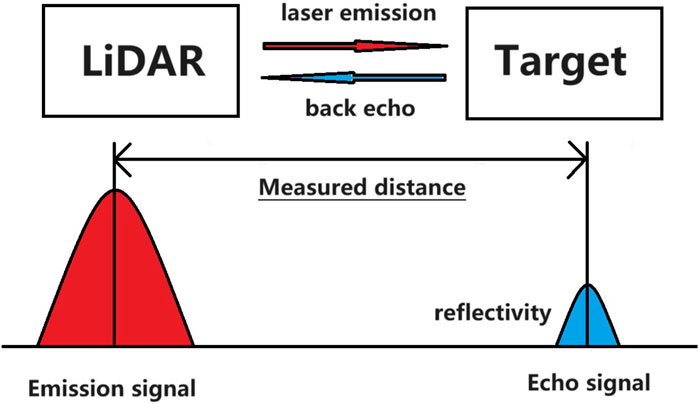
LiDAR is a derivative technology application of laser ranging technology, which primarily uses the time-of-flight (TOF) algorithm to probe objects [2]. The process involves emitting a laser pulse, which then travels through the air for a certain period of time before hitting the target and reflecting. The returning signal is captured by the receiving antenna, and the time difference between the emission signal and the return signal is calculated to measure the distance. The reflectivity information of the target is also calculated based on the pulse width of the return signal waveform, as shown in Figure 1.
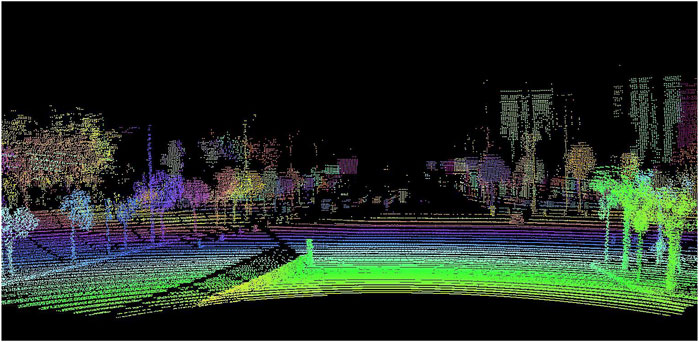
Automotive LiDAR technology is based on rangefinders, where an additional scanning device is added to direct each emitted laser pulse signal toward a specific area within the imaging field of view. The echo signals generated by the light pulse are collected, allowing for the determination of distance information for a specific location within the imaging field using a TOF algorithm. As the scanning device rotates rapidly, distance information for every pixel point inside the entire imaging field can be obtained over a brief period. By recording the imaging coordinates aimed by the scanner at each emission of laser and mapping the corresponding distance information onto the emission coordinates repeatedly, the point cloud imaging process for the entire imaging region can be completed [3], as shown in Figure 2. The main advantage of this method is its ability to acquire vast amounts of information within a short time frame, greatly enhancing the efficiency and precision. Furthermore, due to its reliance on the TOF algorithm, it offers high accuracy and reliability, making it a trustworthy measuring method.
The performance of LiDAR systems is influenced by two critical factors: the frequency of the laser emission and the speed of the scanning mechanism. Both factors contribute to determining the spacing between each scanned point, commonly referred to as the point cloud resolution. If the speed of the scanning mechanism remains constant, then the frequency of the laser emission directly impacts the resolution of the point cloud. In other words, the higher the frequency of the laser emission, the higher the resolution of the point cloud. High resolution means a more detailed image, capable of capturing more details, thus extracting environmental information more fully. Therefore, the performance of LiDAR systems improves as the emission frequency increases. The emission frequency f of the laser points for LiDAR can be expressed as
where V represents the field of view, F represents the frame rate, Line represents the number of scan lines, Resolution represents the resolution, and Channel represents the number of channels. Typically, mainstream automotive LiDAR today has scanning line counts exceeding 100. Taking an example of automotive LiDAR with a 120-degree scanning field of view, a frame rate of 10 frames per second, four channels for parallel scanning, a horizontal resolution of 0.1, and 134 scanning lines, calculations show that the device’s laser emission frequency happens to be approximately 400 kHz.
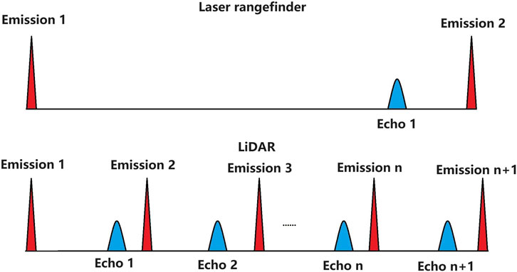
The high-speed scanning requirements of LiDAR are ensured by increasing the emission frequency of the laser to above 400 kHz, although its high emission frequency may also cause some problems at the same time. The emission frequency of 400 kHz causes the range of a single emission to be only 375 m, and the range of 500 kHz further declines to 300 m. The range capability of the 1,550 nm LiDAR transceiver system can easily exceed 400 m, and targets outside the effective range still contain additional information on traffic conditions, which is an important part of autopilot driving and cannot be discarded [4]. A comparison between the effective ranges of the LiDAR and the laser rangefinder is shown in Figure 3.
Echoes that exceed the effective range will be captured equally by the receiving system, causing the LiDAR to incorrectly recognize the echo from the last as the current laser emission. In this case, the distance value is incorrect and will affect the calculation procedure of the next range, significantly limiting the telemetry performance of LiDAR and introducing numerous ghost noises into the point cloud, which causes misjudgment by the autopilot driving algorithms and affects the safety of driving [5, 6]. Such a problem of failing to distinguish the corresponding emission of the echo is generally described as range ambiguity.
After solving the problem of range ambiguity, the application of point cloud obtained by automotive LiDAR will be significantly enhanced. First, it can break through the distance limitation of single-point ranging and provide a wider detection range for the autonomous driving system of the vehicle. Second, by improving the number of effective ranging points at long distances, it can provide more detailed judgment data for autopilot algorithms, thereby realizing earlier discovery of potential risks in the surrounding environment and enhancing the safety of vehicle autonomous driving. Therefore, solving the problem of distance ambiguity in laser radars has significant implications for enhancing the safety and reliability of car autonomous driving. It not only contributes to protecting the personal safety of drivers but also enhances people’s awareness of autonomous driving safety, indirectly promoting widespread use and development of car autonomous driving.
Range ambiguity in LiDAR is notably solved by adding specially coded information to the laser emission. Aircraft telemetry LiDAR uses multi-wavelength lasers alternately emitting and finally fusing imaging of each wavelength information [7]. However, due to the complex structure and high cost of multi-wavelength laser transceiver systems, it is difficult to be applied to automotive LiDAR [8]. SLAM LiDAR uses a rotating mechanism to perform cyclic circumferential sweeping in a short period, and the ambiguity distance is solved using the method of correlating the front and rear frames. Automotive Lidar has high real-time imaging requirements, and the same target point in the front and back frames may undergo large displacements, which cannot be correlated and computed using this method [9, 10].
Laser pulse cluster sequence coding is also utilized to solve the range ambiguity problem [11, 12]. A pulse cluster signal is emitted in a short period, and the correspondence between the emitted pulses and the echo signals is distinguished by recognizing the pulse sequence. Yet, it will seriously reduce the peak power of the laser pulse, leading to a decline detection capability of the core metric of LiDAR. Frequency-modulated continuous wave (FMCW) modulates the laser emission frequency to solve the distance ambiguity [13, 14], but it is still not the optimal solution for automotive LiDAR due to its immaturity and unreliability.
Above all, the current automotive LiDAR solution needs to take cost, maturity, and other issues into account, and because its scanning principle has many limitations for solving the range ambiguity problem, a comparison between the options is shown in Table 1. Therefore, solving the problem of range ambiguity at a high emission frequency while using a single-wavelength pulsed laser is one of the priority contents of LiDAR design. The processing speed of the algorithm for the continuous burst data of LiDAR also needs to be considered to avoid data jamming or lagging [15, 16].
In this paper, a range ambiguity classification algorithm based on a single-wavelength pulsed laser and accelerated by an FPGA platform is proposed for the first time in the field of automotive LiDAR [17–19]. This method can accomplish the solution of the range ambiguity problem by encoding the trigger signal with a pulsed laser. The algorithm is considered to be suitable for FPGA system transplantation, and it is convenient to be implemented in FPGA and can satisfy the demand for high-speed point cloud data processing by establishing pipeline processing. The algorithm is transplanted to the automotive LiDAR system for traffic evaluation. After the algorithm calculation, the LiDAR’s ranging ability is significantly improved, and the edge of the long-distance target is notable, without any blocking or jamming in the processing of point cloud data. It excellently satisfies the algorithm design requirements and solves the range ambiguity problem.
2 Modeling and simulation of laser interval coding
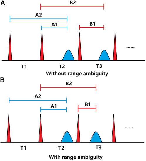
The essence of range ambiguity is that the laser emission frequency is too high, causing the effective range of a single laser emission to become too short to accommodate the echo signal from a farther target. Assuming that the emission point K corresponds to the echo, there are two circumstances: the echo EK can be accommodated by the Kth effective range, and the echo EK will be present before the (k+1) emission instant, without range ambiguity at this point. On the contrary, when the echo EK appears after the (k+1) emission instant, range ambiguity will have occurred. These two situations are illustrated in Figure 4.
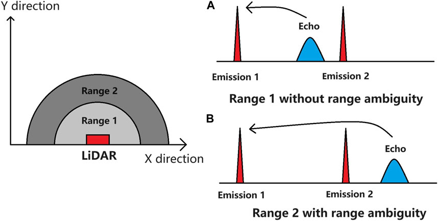
FIGURE 4. Relationship between effective range and range ambiguity. (A) Without range ambiguity area; (B) with range ambiguity area.
To solve the range ambiguity and obtain the real distance value, it is necessary to judge the echo data and whether the ambiguity occurs. The crux of this algorithm is to discriminate ambiguous echoes through a unique design of the emission interval coding. Assuming that the minimum value of the laser trigger interval is T1 and considering the equal incremental value by N, then the laser trigger interval can be expressed as
where k represents the kth light emission.
For better illustration, the range ambiguity has been simplified to within the two emission intervals. Calculation of a single ranging result yields two sets of data, the first of which is the ranging value belonging to (k+1) emission, and the second belongs to the kth emission. There is a difference between those two sets of data in the time interval code N. Assuming that the same target will be hit by at least two laser beams, the range data resulting from the two beams should be the same, which means that the two ranging results will be correlated. Therefore, four sets of range ambiguity data will be generated between the two ranging points: the range1 data A1 and range2 data A2 of the first point A and the range1 data B1 and range2 data B2 of the second point B, as shown in Figure 5.
It can be seen in Figure 5 that there exists the following equation:
Without range ambiguity, the echoes of A and B points will be kept in their respective intervals, due to the encoding of the emission interval, so that A1 = B1 and A2 ≠ B2. When range ambiguity occurs, the real ranging values of points A and B at this time should be added to the last emission interval because of the existence of interval coding, so that A1 ≠ B1 and A2 = B2. Considering that there is a certain error in measurement, the ranging values of A and B points cannot be exactly equal, assuming that there is a threshold Lim < emission interval difference N, and the following ambiguity judgment criteria are considered:
By employing this method, the measurement data between each range are effectively distinguished, and the problem of range ambiguity can be solved.
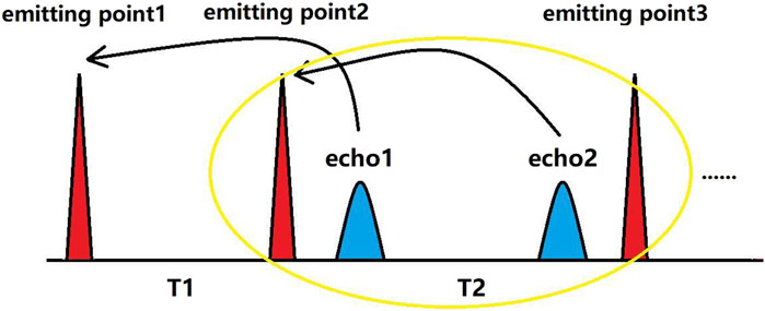
In the actual LiDAR application, there are large numbers of noise signals, multiple target echoes, and radar interference, which will lead to the existence of multiple echoes in the same interval of laser-emitting. In the process of resolving the range ambiguity, the best situation is that each light-emitting interval contains only one echo signal, in which the difficulty for the algorithm to judge the echo information is the minimum. It is very difficult to solve the range ambiguity problem if the data in which multiple-echo overlapping occurs. Noise signals and multiple echoes are related to the actual measurement target, and the signals generated by this process are beyond control. However, the multiple echoes due to distance ambiguity can be avoided by the design of encoding with laser intervals. According to the characteristics of the incremental encoding, when the echo of the T1 interval cannot be accommodated by T1, while the T2 interval echo can be accommodated due to the increase in the T2 interval, then there will be two echoes at the same interval T2, as shown in Figure 6. Such a situation that occurs when the echoes occupy the region between the minimum and maximum values of the interval coding, in which the interval coding is constantly changing, is called code overlapping.
The frequency of multiple-echo overlapping can be used to evaluate the merit of laser emission interval codes, and attempts should be made to avoid their occurrence, ensure the accuracy of range ambiguity resolution, and prevent the resolution method from being too complex to satisfy FPGA implementation [20]. Since there are numerous combinations of codes, it is necessary to construct a simulation model of laser interval codes and range ambiguity to simulate the possible situation of multi-echo overlapping in the actual procedure. In this paper, the MATLAB simulation process can be divided into two steps: the first step is to traverse the echo data of the designed laser emitting interval codes and statistically select the best code from the traversal results according to the aforementioned superiority criteria. The second step is to analyze the range ambiguity of the optimal code, design a decoding algorithm that complies with FPGA, and transplant it into the LiDAR system to verify the effectiveness and reliability of the algorithm.
The hardware of LiDAR generally determines its effective range capability to be approximately 400 m, and the laser emitting interval center frequency to be approximately 600 kHz. The minimum value is not less than 500 kHz, and the maximum value is not larger than 700 kHz to satisfy the demand of the point cloud resolution requirement by the autopilot. According to the assumption that the minimum echo distance without range ambiguity is approximately 210 m (emission frequency 700 kHz) and the range capability of LiDAR is limited to 400 m, the range can be simply divided into range1 and range2. In the actual situation, a target with at least three ranging points is generally considered a valid target; hence, three data with a certain error jitter are generated each time as the simulation input. The simulation of different emitting interval codes according to the aforementioned conditions is described in the following paragraph.
First, a temporal sequential space containing multiple cycles of which interval codes need to be verified is established. Subsequently, each emission instant corresponding to the interval will be numbered and recorded. Finally, three sets of data representing the same valid target are continuously generated until the entire 400 m range is traversed, and the occurrence of multiple-echo overlapping within each code will be recorded.
Setting the threshold value Lim at 4.5 m, the range ambiguity can be solved by setting the interval coding above 81.3 ns. For the codes’ flapping position, which are more likely to have multiple-echo overlapping, and the whole 400 m valid detection range, the simulation of the six designed codes has been undertaken 10,000 times. The statistics of the number of occurrences of echoes overlapping are shown in Table 2.
From the simulation results, it can be seen that under the same threshold and without changing the coding sequence, only modifying the coding interval time will not have a significant effect on the frequency of multi-echo overlapping. With codes Ⅰ or Ⅱ, multi-echo overlapping will occur frequently when the coding interval is increasing. In code Ⅲ, multi-echo overlapping occurs within the range from 1,550 to 1950 ns using a decreasing code, although the reduction of multi-echo overlapping frequency is limited due to the large flapping amplitude of the interval code. By reducing the flapping amplitude of the code, code Ⅳ makes the probability of occurrence of multi-echo overlapping decrease by approximately 20.4% compared with code Ⅲ, which proves that the flapping amplitude when the code is increasing is one of the important factors affecting the occurrence of multi-echo overlapping.
Based on the aforementioned conclusions, code Ⅴ has been designed, which is loop-backed to ensure that the amount of flapping at the time of coding increase is minimized, and it can be seen that the occurrence of multi-echo overlapping is decreased again by approximately 15.2%. Subsequently, within the range allowed by the threshold Lim, the coding interval is compressed to 50 ns to obtain code Ⅵ. Compared with the simple incremental sequence codes Ⅰ and Ⅱ, code Ⅵ reduces the multi-echo overlapping probability by approximately 71.5%, which effectively improves the reliability of the range ambiguity solution.
Finally, code Ⅵ is selected as a sample to generalize the range ambiguity that occurs during the simulation and to design an algorithm that can be utilized in the LiDAR platform according to the demands of FPGA.
3 Implementation of the algorithm with FPGA acceleration
Different from embedded systems, FPGA can readily implement parallel data processing and ensure strict control of data processing delay [21–23]. FPGA is commonly used to accelerate the processing of large amounts of data and in systems with strict speed requirements. However, its complexity, inflexibility, and long development cycle require advanced consideration of specific FPGA implementation when designing an algorithm. For the automotive LiDAR range ambiguity algorithm in this article, the following aspects are considered:
1) FPGA development is more complicated compared to embedded systems, so it is necessary to simplify the complexity of FPGA algorithms as much as possible to shorten the development cycle and verification difficulties.
2) FPGA internal resources are valuable, so it is unable to cache too much data in the whole process to ensure real-time and resource requirements.
3) FPGA internal data processing timing requirements without the block of pathways and the abnormal transmission.
4) When FPGA is a LiDAR central control chip, it is necessary to consider the data information that can be generated or transmitted to facilitate the utilization of the algorithm before the design.
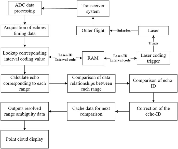
LiDAR requires FPGA to provide a constant width pulse signal as the laser trigger signal, and the interval of the trigger pulse is controlled by the counting logic of FPGA. Therefore, it is possible to number each trigger pulse signal as laser-ID, which will be the index of the RAM, and the corresponding emission interval of each laser-ID also will be stored in the RAM. By searching the RAM, FPGA will be able to obtain each range length corresponding to each laser trigger. FPGA will update the laser-ID once when generating a trigger signal, and according to the time sequence relationship between the echo signal and the trigger signal, the echo number (echo-ID) corresponding to the measurement interval will be able to be obtained. Without range ambiguity, the echo-ID of the echo signal should correspond to the same laser-ID; when range ambiguity occurs, the echo-ID needs to be corrected to the real laser-ID.
In the process of implementing the classification algorithm, the algorithm architecture is designed by caching the two points and outputting the third point, and FPGA needs to obtain the interval code, laser-ID, and echo-ID for comparison in the classification algorithm. Finally, the echo ranging value and the echo-ID will be corrected according to the comparison results, so that the real range value after solving the range ambiguity can be obtained. Combining the aforementioned analysis with the simulation results in the previous chapter, the classification of the distance ambiguity of code Ⅵ has been conducted, and the corresponding echo-ID correction method has been determined according to various classification cases. After generalization, 10 different classification cases are shown in Table 3.
FPGA can implement this classification comparison easily. After obtaining the echo timing value, FPGA also required to complete the read RAM to find the interval codes, calculate the three multi-range values, three multi-range value comparisons, three laser-ID comparisons, classification table lookup, three echo-ID corrections, and ranging result output process, which will consume a long clock processing cycle. The data processing process of the algorithm is shown in Figure 7.
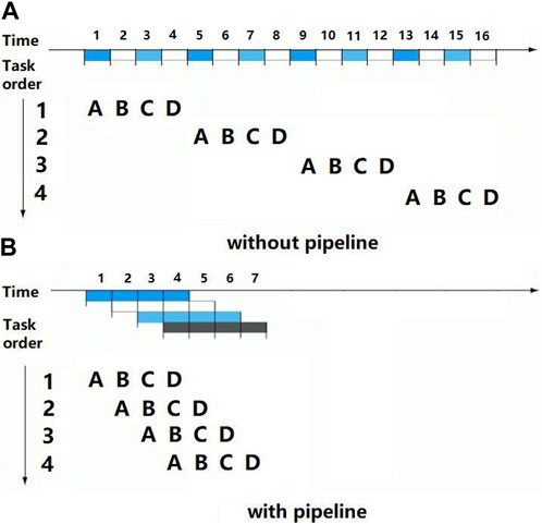
When using a simple timing processing logic, FPGA needs to ensure that the input data remain constant before completing the whole set of processes; otherwise, the output data will be anomalous. In addition, LiDAR may use multi-channel scanning, which means that the same laser emitting may generate multiple range points at the same time. The data that have to be processed at the same time will be considerably increased, and the FPGA data processing speed must be further enhanced. The pipeline is a technique that can be employed to enhance the data throughput of FPGA, the main idea being to decompose a repetitive process into several sub-processes, each of which is implemented by a dedicated functional segment. Multiple processes are staggered in time and pass through each functional segment sequentially, so that each sub-process can be carried out in parallel with other sub-processes, as shown in Figure 8.
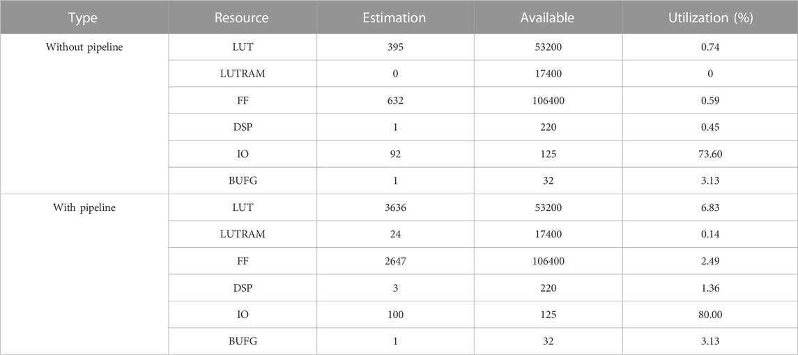
As can be seen, the pipeline architecture can effectively solve the problem of inefficiency in serial data computation, but it occupies more resources of FPGA, such as LUT, DSP, and RAM. Therefore, it is necessary to compare the resource occupancy of the pipelined operation to assess its feasibility. The resource occupation of the pipeline processing is shown in Table 4 after the completion of the classification range ambiguity algorithm processing process using Xilinx 7020 FPGA. Compared to the resources of the whole FPGA, the resource consumption is still within an acceptable limit, and the algorithm is still able to employ a pipeline procedure.
According to the table, the pipeline processing increases the LUT resource consumption by 10 times and the FF resource consumption by four times compared to the consumption before adding the pipeline. However, the resource consumption remains within an acceptable limit, and the algorithm is still able to employ a pipeline procedure.
The classification range ambiguity algorithm based on the pipeline architecture has been successfully transplanted to the automotive LiDAR system and verified through a vehicle traffic test. As shown in Figure 9A, the LiDAR’s ranging capability is limited to 300 m without the algorithm. With the algorithm, the LiDAR platform’s range capability can exceed the limitation of 300 m, and the building target can still be detected at 480 m, as shown in Figure 9B.
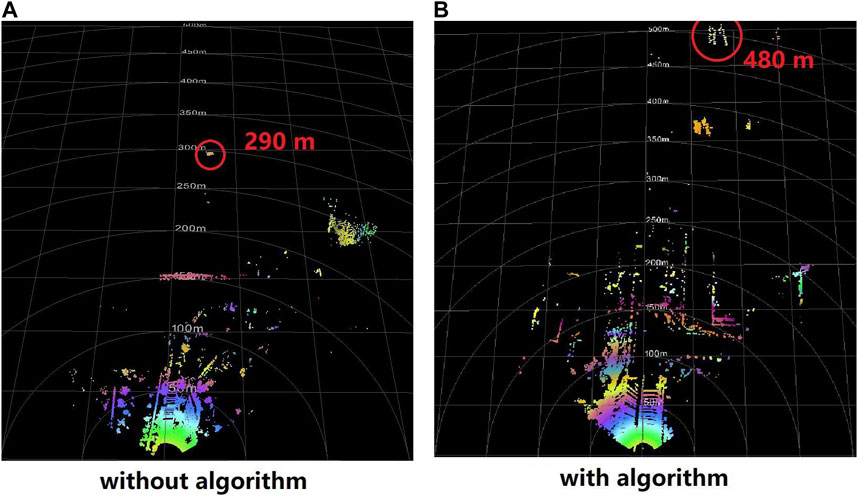
FIGURE 9. Comparison of the classification range ambiguity algorithm. (A) Without algorithm; (B) with algorithm.
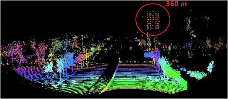
As can be seen in Figure 10, the edges of the target’s point cloud at a longer distance are still sharp and clear, which meets the recognition requirements of the autopilot algorithm perfectly. In conclusion, the range ambiguity problem of automotive LiDAR is effectively solved by the algorithm in this article.
4 Conclusion
A classification range ambiguity algorithm for automotive LiDAR has been proposed in this paper, which is designed to work with an FPGA platform for data processing acceleration. The algorithm has been analyzed and compared with different laser interval coding methods through simulation, and the timing and resource requirements of FPGA have been taken into consideration for its design. To improve the data processing efficiency, a pipeline architecture has been employed for the FPGA platform implementation of the algorithm. The algorithm has been tested in a traffic scenario, and it has helped LiDAR solve the range ambiguity problem and improve its long-distance measurement capability while maintaining high resolution.
The proposed algorithm not only enhances the performance of LiDAR but also provides a reference for exploring the combination of LiDAR and FPGA. In future research, the pulse width, amplitude, emission interval coding, and other information of the pulsed laser can be integrated to improve the echo extraction ability in the multi-echo overlapping area and combined with the parallel processing characteristics of FPGA to improve the performance and flexibility of the algorithm, achieving better point cloud performance and stronger data processing capability.
Data availability statement
The original contributions presented in the study are included in the article/Supplementary Materials; further inquiries can be directed to the corresponding author.
Author contributions
HL: writing–original manuscript and writing–review and editing. SX, LZ, JZ, SW, and YW: writing–review and editing.
Funding
The authors declare that no financial support was received for the research, authorship, and/or publication of this article.
Conflict of interest
Authors HL, SX, LZ, JZ, and SW were employed by Raytron Technology Co., Ltd.
The remaining author declares that the research was conducted in the absence of any commercial or financial relationships that could be construed as a potential conflict of interest.
Publisher’s note
All claims expressed in this article are solely those of the authors and do not necessarily represent those of their affiliated organizations, or those of the publisher, the editors, and the reviewers. Any product that may be evaluated in this article, or claim that may be made by its manufacturer, is not guaranteed or endorsed by the publisher.
References
1. Roriz R, Cabral J, Gomes T. Automotive LiDAR technology: a survey. IEEE Trans Intell Transportation Syst (2022) 23(7):6282–97. doi:10.1109/TITS.2021.3086804
2. Liu J, Sun Q, Fan Z, Jia Y. TOF lidar development in autonomous vehicle. In: 2018 IEEE 3rd Optoelectronics Global Conference (OGC); 04-07 September 2018; Shenzhen, China (2018). p. 185–90. doi:10.1109/OGC.2018.8529992
3. Sohn K, Bernardi A, Neiroukh OR. Effects of input resolution on LIDAR pedestrian localization using deep learning. In: 2021 International Conference on Electronics, Information, and Communication (ICEIC); 31 January 2021 - 03 February 2021; Jeju, Korea (South) (2021). p. 1–4. doi:10.1109/ICEIC51217.2021.9369736
4. Li Y, Ibanez-Guzman J. Lidar for autonomous driving: the principles, challenges, and trends for automotive lidar and perception systems. IEEE Signal Process. Mag (2020) 37(4):50–61. doi:10.1109/MSP.2020.2973615
5. Srivastava AK, Singhal A, Sharma A. Analysis of lidar-based autonomous vehicle detection technologies for recognizing objects. In: 2023 6th International Conference on Information Systems and Computer Networks (ISCON); 03-04 March 2023; Mathura, India (2023). p. 1–5. doi:10.1109/ISCON57294.2023.10112089
6. Roy D, Li Y, Jian T, Tian P, Chowdhury K, Ioannidis S. Multi-modality sensing and data fusion for multi-vehicle detection. IEEE Trans Multimedia (2023) 25:2280–95. doi:10.1109/TMM.2022.3145663
7. Hanto D, Pratomo H, Rianaris A, Setiono A, Sartika S, Syahadi M, et al. Time of flight lidar employing dual-modulation frequencies switching for optimizing unambiguous range extension and high resolution. IEEE Trans Instrumentation Meas (2023) 72:1–8. doi:10.1109/TIM.2023.3235450
8. Rieger P. Range ambiguity resolution technique applying pulse-position modulation in time-of-flight scanning lidar applications. Opt Eng (2014) 53(6):061614. doi:10.1117/1.OE.53.6.061614
9. Volpin F, Chiodini S, Fortuna S, Valmorbida A, Pertile M. 360-deg FOV scanning LiDAR versus non-repetitive scanning LiDAR: a rover navigation experiment. In: 2023 IEEE 10th International Workshop on Metrology for AeroSpace (MetroAeroSpace); 19-21 June 2023; Milan, Italy (2023). p. 470–5. doi:10.1109/MetroAeroSpace57412.2023.10189983
10. Lu H, Pang Y, Li Z, Chen B. An automatic range ambiguity solution in high-repetition-rate airborne laser scanner using priori terrain prediction. IEEE Geosci Remote Sensing Lett (2015) 12(11):2232–6. doi:10.1109/LGRS.2015.2461441
11. Fersch T, Alam MF, Weigel R, Koelpin A. A FPGA correlation receiver for CDMA encoded LiDAR signals. In: 2017 13th Conference on Ph.D. Research in Microelectronics and Electronics (PRIME); 12-15 June 2017; Giardini Naxos - Taormina, Italy (2017). p. 289–92. doi:10.1109/PRIME.2017.7974164
12. Zang Y, Chen H, Yang S, Chen M. High accuracy non ambiguity ToF lidar system based on pseudo-random noise code and phase detection method. In: 2019 Optical Fiber Communications Conference and Exhibition (OFC); 03-07 March 2019; San Diego, CA, USA (2019). p. 1–3.
13. Hwang S, Jang J, Park K. Note: continuous-wave time-of-flight laser scanner using two laser diodes to avoid 2π ambiguity. Rev Sci Instrum (2013) 84(8):086110. doi:10.1063/1.4819260
14. Thakur S, Zele R. Frequency to digital converter based on rational approximation technique for FMCW LiDAR receiver. In: 2022 International Conference on Electrical, Computer, Communications and Mechatronics Engineering (ICECCME); 16-18 November 2022; Maldives, Maldives (2022). p. 1–6. doi:10.1109/ICECCME55909.2022.9988621
15. Zhou G, Zhang H, Xu C, Zhou X, Liu Z, Zhao D, et al. A real-time data acquisition system for single-band bathymetric LiDAR. IEEE Trans Geosci Remote Sensing (2023) 61:1–21. doi:10.1109/TGRS.2023.3282624
16. Zhang X, Huang X. Real-time fast channel clustering for LiDAR point cloud. IEEE Trans Circuits Syst Express Briefs (2022) 69(10):4103–7. doi:10.1109/TCSII.2022.3185228
17. Sugiura K, Matsutani H. A universal LiDAR SLAM accelerator system on low-cost FPGA. IEEE Access (2022) 10:26931–47. doi:10.1109/ACCESS.2022.3157822
18. Queralta JP, Yuhong F, Salomaa L, Qingqing L, Gia TN, Zou Z, et al. FPGA-Based architecture for a low-cost 3D lidar design and implementation from multiple rotating 2D lidars with ROS. In: 2019 IEEE SENSORS; 27-30 October 2019; Montreal, QC, Canada (2019). p. 1–4. doi:10.1109/SENSORS43011.2019.8956928
19. Wang Z, Xu L, Li D, Zhang Z, Li X. Online multi-target laser ranging using waveform decomposition on FPGA. IEEE Sensors J (2021) 21(9):10879–89. doi:10.1109/JSEN.2021.3060158
20. Yu M, Shi M, Hu W, Yi L. FPGA-based dual-pulse anti-interference lidar system using digital chaotic pulse position modulation. IEEE Photon Technol Lett (2021) 33(15):757–60. doi:10.1109/LPT.2021.3093109
21. Han ZJ, Tang X, Wu ZM, Xia GQ. A real-time and anti-interference lidar based on field programmable gate array. In: 2021 19th International Conference on Optical Communications and Networks (ICOCN); 23-27 August 2021; Qufu, China (2021). p. 1–3. doi:10.1109/ICOCN53177.2021.9563654
22. Sun T, Liu Y, Wang Y. Design and implementation of a high-speed lidar data reading system based on FPGA. In: 2019 IEEE International Conference on Real-time Computing and Robotics (RCAR); 04-09 August 2019; Irkutsk, Russia (2019). p. 322–7. doi:10.1109/RCAR47638.2019.9044143
Keywords: automotive Light Detection and Ranging, range ambiguity, laser, FPGA acceleration, autopilot
Citation: Li H, Xiang S, Zhang L, Zhu J, Wang S and Wang Y (2023) A range ambiguity classification algorithm for automotive LiDAR based on FPGA platform acceleration. Front. Phys. 11:1290099. doi: 10.3389/fphy.2023.1290099
Received: 06 September 2023; Accepted: 06 November 2023;
Published: 22 November 2023.
Edited by:
Yaping Dan, Shanghai Jiao Tong University, ChinaReviewed by:
Abhishek Sharma, Guru Nanak Dev University, IndiaHanyang Zhuang, Shanghai Jiao Tong University, China
Copyright © 2023 Li, Xiang, Zhang, Zhu, Wang and Wang. This is an open-access article distributed under the terms of the Creative Commons Attribution License (CC BY). The use, distribution or reproduction in other forums is permitted, provided the original author(s) and the copyright owner(s) are credited and that the original publication in this journal is cited, in accordance with accepted academic practice. No use, distribution or reproduction is permitted which does not comply with these terms.
*Correspondence: You Wang, eW91d2FuZzIwMDdAYWxpeXVuLmNvbQ==
 Haoyu Li
 Sihua Xiang1