- 1College of Electronics and Information Engineering, Sichuan University, Chengdu, Sichuan, China
- 2China Space Sanjiang Group Co., LTD., Wuhan, Hubei, China
This study employs the power spectrum inversion method to generate the phase screens of atmospheric turbulence over the sea, the theoretical model of the vortex beam array emitted by a focusing system through anisotropic non-Kolmogorov maritime atmospheric turbulence was built. The propagation characteristics of the vortex beam array were investigated theoretically and compared to those of the Gaussian beam array. The results show that the vortex beam array is less affected by turbulence and exhibits stronger resistance to the turbulence. On this basis, using the evaluation parameters including the relative beam width and the beam wander, the influences of various parameters of the vortex beam array and atmospheric turbulence, such as topological charge, beamlet width, number of beamlets, anisotropy factor, and power law, on its propagation characteristics through anisotropic non-Kolmogorov maritime atmospheric turbulence were studied extensively. The results can provide a useful reference for the applications of the vortex beam array in optical communication through the maritime atmosphere.
1 Introduction
Vortex beams, known for their distinctive wavefront structure and well-defined photon orbital angular momentum, have been widely used in various fields such as space optical communication, optical information processing, quantum information encryption, and biomedical applications. However, the presence of atmospheric turbulence introduces random perturbation in the phase of the beam, leading to adverse effects such as beam spreading and beam wander. These effects inevitably degrade the beam quality and reduce the amount of received energy, thereby limiting the practical applications of laser beams. Fortunately, beam combining has emerged as an effective approach to increase laser power and mitigate atmospheric turbulence [1]. In recent years, researchers have investigated the propagation characteristics of vortex beam arrays in terrestrial atmospheric turbulence based on their unique properties. Chen et al. [2] compared the beam wander of a single Airy vortex beam with that of an array of Airy vortex beams, revealing that the beam wander of the Airy vortex beam array is relatively small. Liu et al. [3] studied the propagation characteristics of a radial phased-locked partially coherent flat-topped vortex beam array in a non-Kolmogorov medium, analyzed the evolution of the optical intensity under different turbulence conditions, and calculated the complex coherence of the beam array at the receiving plane. Luo et al. [4] investigated the propagation and spreading of the radial vortex beam array in turbulence and analyzed the evolution of the optical field. Li et al. [5] explored the centroid wander of the radial Airy vortex beam array in slant atmospheric turbulence and investigated the effects of the topological charge, zenith angle, and outer scale of turbulence on beam wander.
Nevertheless, with the rapid development of information technology and the increasing demand in military and scientific research, the influence of atmospheric turbulence on the optical communication performance of lasers through maritime atmospheric turbulence has attracted increasing attention. However, unlike the terrestrial environment, the propagation characteristics of laser beams through maritime atmospheric turbulence exhibit some significant differences due to the combined effects of temperature and humidity fluctuations in the maritime atmosphere. Consequently, discussions regarding the propagation characteristics of laser beams through maritime atmospheric turbulence have been conducted [6–16]. However, most of the research studies have focused on the different types of laser beams, such as Gaussian beams and various vortex beams, with limited studies on vortex beam arrays. In particular, the propagation characteristics of vortex beam arrays through anisotropic non-Kolmogorov maritime atmospheric turbulence by a focusing emission system have not been discussed yet.
In this paper, the power spectrum inversion method is used to generate random phase screens conforming to the non-Kolmogorov spectrum through Fourier transform. Combined with the non-adaptive phase screen algorithm, the propagation characteristics of vortex beam arrays through anisotropic non-Kolmogorov maritime atmospheric turbulence were numerically simulated and analyzed. Furthermore, the effects of the topological charge, beamlet width, number of beamlets, anisotropy factor, and power law on the relative beam width and beam wander were studied in detail.
2 Basic theory
2.1 Beam model
We assume that a radial vortex beam array is composed of N equal Laguerre–Gaussian (LG) beams, which are symmetrically arranged on a ring with a radius R, and the separation angle between two adjacent LG beams is θ0. The beam waist is denoted as w0, and for the nth beam, its position on the coordinate plane can be described as (an and bn). Here, the centrifugal parameter an = Rcosθn, bn = Rsinθn, θn = nθ0, θ0 = 2π/N, and n = 1, 2, 3,···, N.
To establish the propagation model for the LG vortex beam array through maritime atmospheric turbulence, the laser spots underwent degradation after passing through maritime atmospheric turbulence with a focusing lens along the z-axis. It is particularly important to note that the aperture D is the total focal aperture of the radial array beam, which remains constant. The LG vortex beam array is inscribed on the focal aperture. The schematic diagram of the radial distribution beam array and its propagation model through maritime atmospheric turbulence is given in Figure 1.
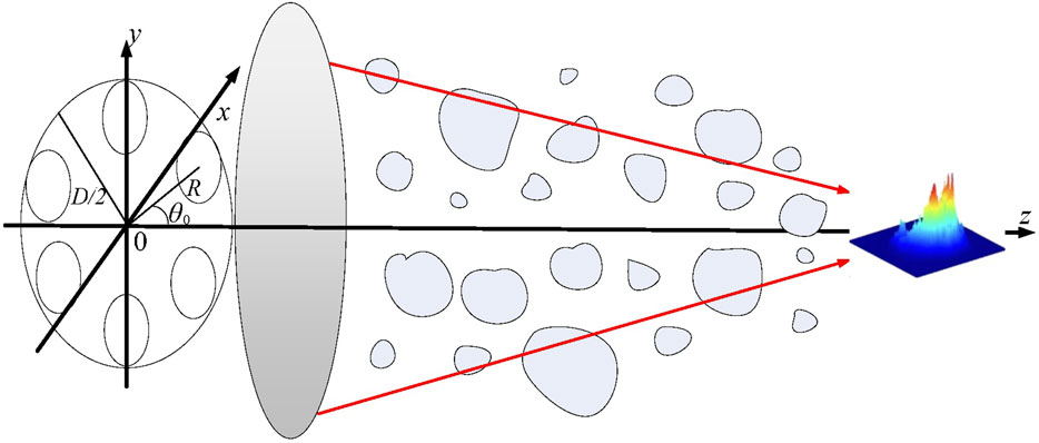
FIGURE 1. Propagation of the LG vortex beam array through maritime atmospheric turbulence using a focusing lens system with focal aperture D.
The initial field distribution of a single LG vortex beam on the z = 0 plane is given as follows:
where r and θ represent the radial and azimuthal coordinates, respectively. eimθ denotes the helical phase,
2.2 Anisotropic oceanic atmospheric turbulence spectrum model
Assuming that anisotropy only exists in the plane perpendicular to the propagation direction of the beam (z-axis), the anisotropic non-Kolmogorov turbulence spectrum through maritime atmospheric turbulence can be expressed as [17]
where α represents the spectral power law index, which can also be called the power law; A(α) denotes the constant that ensures the consistency between the refractive index structure function and the corresponding power spectrum;
Based on the aforementioned equations, we can see that the only difference in the expression of the turbulence power spectrum is the values of the parameters a1 and a2. Consequently, the propagation characteristics of focused beams through maritime atmospheric turbulence and terrestrial atmospheric turbulence are generally similar, with the exception that the results of the beam wander and relative beam width may vary. To simulate the propagation of optical fields through maritime atmospheric turbulence, the spectrum inversion method is employed to generate random phase screens that decrease in size with the increase in propagation distance. The numerical simulation is carried out with the use of the multi-phase screen method combined with subharmonic low-frequency compensation applied to the phase screens. The schematic diagram of the numerical simulation of beam propagation, with smaller phase screens with increase in the propagation distance, is shown in Figure 2.
When performing numerical simulations for the propagation of the laser beam in the atmosphere, the commonly used multi-layer phase screen method assumes equal phase screen widths and grid spacing on each phase screen. However, with respect to the propagation of focused beams, the spot radius becomes smaller upon propagation, resulting in a decrease in the proportion of the spot occupying the computational grid. Setting the phase screen widths and grid spacing to the same size as the emission plane will lead to a decrease in the sampling points of the spot, limiting the ability to adequately describe the spot. To accurately simulate the intensity distribution on the focal plane, non-adaptive coordinate transformation can be performed based on the initial spot size and the spot size at the focal plane. For the focal beam system discussed in this manuscript, we assume that the initial spot radius is denoted as a and the Airy beam radius at the focus is R (R = 0.61zƒλ/a). When calculating the light field distribution at z = zƒ, due to turbulence-induced beam spreading, the beam diameter Dƒ can be taken as a multiple of the Airy beam radius, i.e., Dƒ = kR, where the value of k depends on the turbulence intensity. Generally, stronger turbulence results in greater beam spreading and further a larger value of k. Therefore, selecting an appropriate value of k ensures that the spot at the focus is centered on the screen. In this paper, appropriate values for D0 and Df are set, and the widths and grid spacing of each phase screen are adjusted during the propagation. This allows for wider phase screen widths and grid spacing in areas with larger spots and narrower ones in areas with smaller spots, while maintaining a constant total number of computational grids (N × N) on each phase screen.
As shown in Figure 2, based on the initial spot radius at z = 0 and the spot radius at the focal length zf, the initial phase screen size D0 and the focal plane phase screen size Df are set. According to the geometric relationship, the coordinate transformation scale factor B(z) at the z plane is
where
Then, the relationship between the transformed field u′ and the original field u is
The propagation equation is
After solving the optical field u′(x′, y′, z′) numerically on the phase screen in the coordinate system (x, y, z) using the multi-phase screen method according to Eq. 4, the solution in the original coordinate system u(x, y, z) is obtained based on Eq. 3.
3 Results and discussion
The values of the simulation parameters are shown in Table 1. Unless otherwise specified, the parameters are set as follows: the refractive index structure parameter
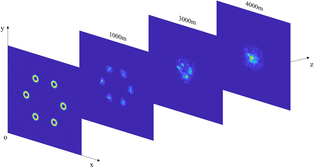
Using a self-developed four-dimensional simulation program, the effects of different topological charges, beamlet waist widths, the number of beamlets on the relative beam width, and the beam wander of the radial vortex beam array are analyzed. The evolution of the light field distribution through the anisotropic non-Kolmogorov atmospheric turbulence is shown in Figure 3.
Due to the refraction caused by large-scale turbulent vortices, the central position of the received beam randomly changes, resulting in beam wander. This phenomenon affects the stability and reliability of laser applications. The change in the centroid position of the beam spot is usually used to describe the beam wander. The centroid position of the beam spot is defined as follows [21]:
where ρ is the position vector at any position on the receiving plane, z is the beam propagation distance, and
When the beam propagates through the maritime atmosphere, it also undergoes beam spreading due to the influence of the atmospheric medium. The second-order moment beam width is considered to be the most rigorous according to the ABCD law. The definition of the second-order moment beam width [22, 23] is
The beam spreading through the maritime atmosphere is influenced by both free-space diffraction and non-Kolmogorov turbulence. In order to intuitively evaluate the ability of array beams to suppress the turbulence spreading effect, the relative beam width is used for description:
where the relative second-order moment beam width wr is defined as the ratio of the second-order moment beam width wturb transmitted through the turbulent atmosphere to the second-order moment beam width wfree at the same propagation distance in free space.
3.1 Influences of laser array parameters
By utilizing the parameters mentioned previously, numerical simulation was carried out to illustrate the influences of laser array parameters. The typical results are shown in Figures 4–6.
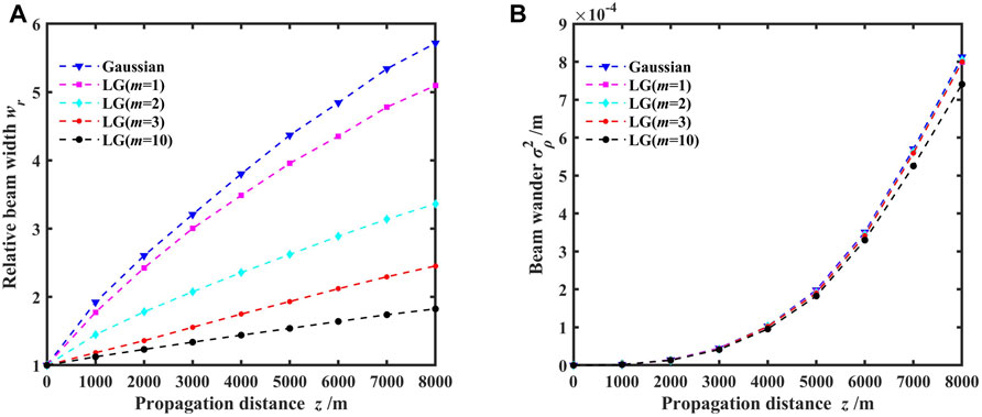
FIGURE 4. Variations of the relative beam width and beam wander for different propagation focal planes with topological charges; (A) relative beam width and (B) beam wander.
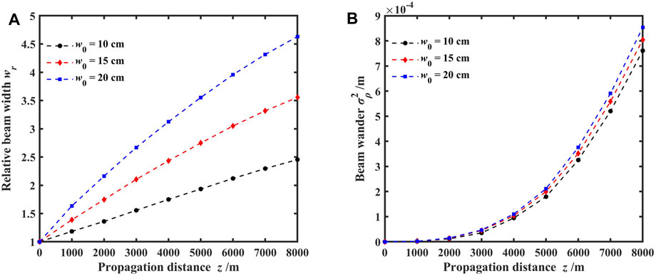
FIGURE 5. Variations of the relative beam width and beam wander for different propagation focal planes with varying beamlet waist widths; (A) relative beam width and (B) beam wander.
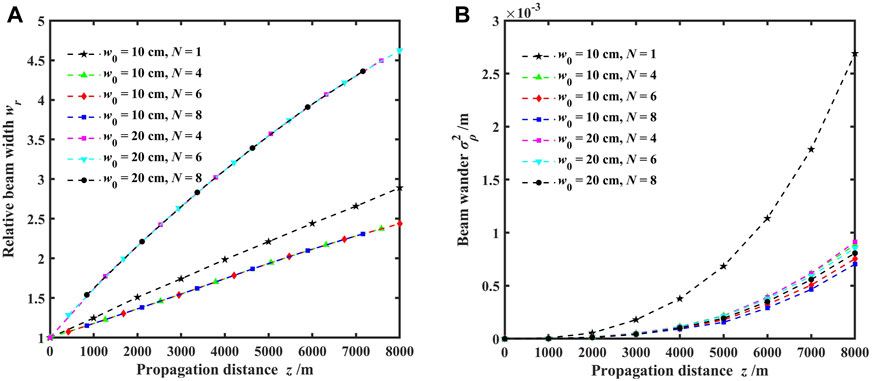
FIGURE 6. Variations of the relative beam width and beam wander for different propagation focal planes with varying numbers of array beams; (A) relative beam width and (B) beam wander.
Figure 4 shows the variations of the relative beam width and beam wander for different propagation focal planes with topological charges. The topological charges of the vortex beam array were set to 1, 2, 3, and 10, with the case of the topological charge of 0 corresponding to Gaussian beam arrays. It is evident from Figure 3 that as the propagation distance through the maritime atmosphere increases, the beam spreading and beam wander of vortex beam arrays also increase. This is because of the increased turbulence intensity and its impact on the beam with increasing propagation distance. Figure 4A shows that larger topological charges result in smaller relative beam widths at the same focal plane. Notably, the relative beam width is smallest for a topological charge of 10, indicating that vortex beams possess better resistance to turbulence and superior propagation capabilities compared to a Gaussian beam. Figure 4B shows a slight impact of topological charge on beam wander, except when the topological charge reaches 10, resulting in a decrease in beam wander with increasing propagation distance. This reveals that the topological charge has a limited effect on the beam wander.
Figure 5 depicts the variations of the relative beam width and beam wander for different propagation focal planes with beamlet waist widths. The initial beam waist widths of the beamlets were set to 10, 15, and 20 cm. Figure 5A demonstrates that the relative beam width increases with increasing propagation distance for each focal plane, indicating that the beam spreading caused by turbulence becomes more pronounced with greater propagation distance. Additionally, as the initial beam waist width of the beamlets increases from 10 to 20 cm, the relative beam width at the same focal plane also increases, signifying the influence of the initial beam waist width on beam spreading at the focal plane. The effect can be attributed to the diffraction effects of the beam, with a larger initial beam waist width leading to a larger relative beam width and more severe beam spreading at the focal plane due to turbulence. Figure 5B shows an appropriately exponential increase in beam wander with propagation distance. Initially, the initial beam waist width of the beamlets has a slight impact on the beam wander at the focal plane. However, as the propagation distance increases, larger initial beam waist widths result in an increased beam wander. This suggests that a larger initial beam waist width corresponds to a smaller circular radius R when the focal aperture is fixed, and smaller circular radii are more susceptible to the effects of turbulence. Furthermore, the variation in the initial beam waist width has limited impact on the beam wander at the focal plane.
Figure 6 demonstrates the variations of the relative beam width and beam wander for different propagation focal planes with the numbers of array beams. The numbers of array beams were set to 4, 6, and 8, with initial beam waist widths of the beamlets set to 10 and 20 cm. Figure 6A reveals that the number of array beams has a slight impact on the relative beam width at the focal plane, whereas the initial beam waist width of the beamlets has a more significant influence. Larger initial beam waist widths result in more severe beam spreading and larger relative beam widths at the focal plane, consistent with the analysis presented in Figure 5A. Figure 6B demonstrates that both the number of array beams and the initial beam waist width of the beamlets have limited effect on the beam wander at the focal plane. Simulation results indicate that even when the beam propagates up to 8 km, the beam wander remains at the millimeter level. Furthermore, when compared to a single vortex beam (N = 1), the vortex beam array exhibits significantly reduced relative beam width and beam wander, indicating that the vortex beam array possesses a better turbulence mitigation effect [24–27].
3.2 Influences of atmospheric turbulence parameters
We also discuss the propagation properties of the vortex beam array affected by the maritime atmospheric turbulence parameters.
Figure 7 presents the variations of the relative beam width and beam wander for different power laws with turbulence intensities and turbulence properties. The turbulence intensities are set to 1 × 10⁻¹⁴ m3−α, 5 × 10⁻¹⁵ m3−α, and 1 × 10⁻¹⁵ m3−α. Here, the focal plane position is set as 4.5 km.
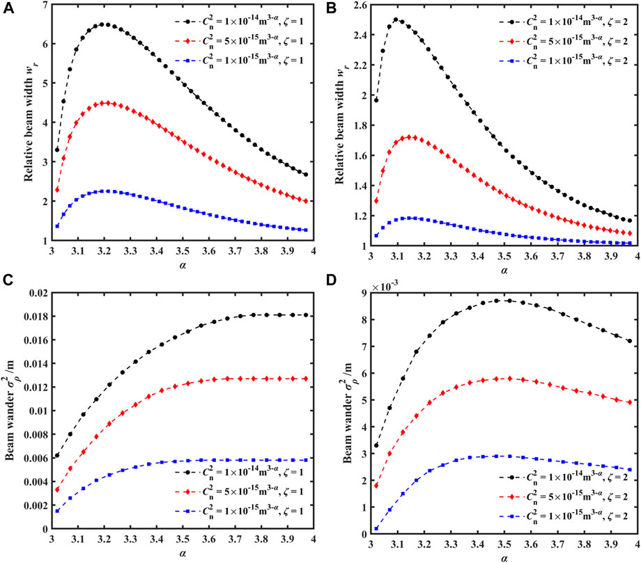
FIGURE 7. Variations of the relative beam width and beam wander for different power laws with turbulence intensities and turbulence properties; (A) isotropic relative beam width, (B) anisotropic relative beam width, (C) isotropic beam wander, and (D) anisotropic beam wander.
Figures 7A, B show that as the turbulence intensity increases, the beam expansion at the same focal plane becomes more severe, resulting in a larger relative beam width. With the increase of the power law α, the relative beam width initially increases rapidly, reaches a peak, and then decreases with further increase of α. According to Ref. [26], the turbulence parameter first increases and then decreases with variation in the power law. Consequently, over a sufficiently long propagation distance, the beam width expansion is primarily affected by the strength of non-Kolmogorov turbulence. Therefore, the relative beam width increases and then decreases with variation in the power law, just like the turbulence parameter. For the case of isotropic maritime atmospheric turbulence with ζ = 1, the extremum of the relative beam width occurs approximately α = 3.2. However, for the anisotropic maritime atmospheric turbulence with ζ = 2, the extremum of the relative beam width occurs between 3.1 and 3.2. Particularly, in the case of strong turbulence and small α, the variation of the relative beam width with α is more pronounced in anisotropic turbulence compared to isotropic turbulence. It is worth noting that when the array beam propagates through anisotropic maritime atmospheric turbulence, the relative beam width at the focal plane is smaller than that through isotropic turbulence, indicating that anisotropy leads to an uneven distribution of turbulence intensity, resulting in the reduced impact of the turbulence on the beam expansion.
Figure 7C shows that in the case of isotropic turbulence (ζ = 1), the beam wander at the focal plane increases with the increase of the power law and then tends to be a constant value. The stronger the turbulence, the larger the beam wander. With the increase of the power law α from 3 to 4, the beam wander corresponding to α = 3 increases from 0.002 to 0.006 m, and the beam wander corresponding to α = 4 increases from 0.006 to 0.018 m. The strength of turbulence directly affects the reception quality of optical communication. Unlike the propagation of beam arrays in isotropic turbulence, the beam wander increases to a maximum value and then slowly decreases with the increase of the power law α, as shown in Figure 7D. Moreover, it can be seen that the beam wander through anisotropic turbulence is smaller than that through isotropic turbulence. Therefore, finding a “window” with weaker turbulence for emission and designing a reasonable layout for laser emission paths are important in practical applications.
Figure 8 shows the variations of the relative beam width and beam wander with the power law α when the anisotropy factors are ζ = 1 (isotropic turbulence), ζ = 2, ζ = 4, and ζ = 8 in the propagation of array beams through anisotropic non-Kolmogorov maritime atmospheric conditions. In simulations, the refractive index structure parameter
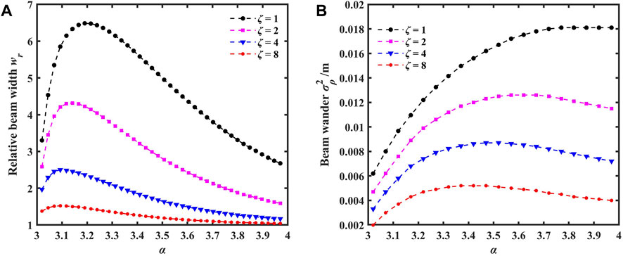
FIGURE 8. Variations of the relative beam width and beam wander for different power laws with anisotropy factors; (A) relative beam width and (B) beam wander.
The power law α corresponding to the extremum point varies with different anisotropy factors ζ, and as the anisotropy factor increases, the α corresponding to the extremum point becomes smaller. It should be pointed out that in the case of isotropic turbulence, the power law α has a greater impact on beam expansion, whereas in the case of anisotropic turbulence, its impact is relatively smaller. Similarly, from Figure 8B, it can be observed that the beam wander of the array beam in isotropic turbulence is the largest. This is because anisotropy affects the distribution of turbulence intensity, and the stronger the anisotropy, the more uneven the distribution of turbulence intensity, resulting in a reduced impact of turbulence on both the beam expansion and the beam wander and further leading to a decrease in the relative beam width and beam wander. Moreover, the influence of the power law α on the beam wander increases slowly and the larger the power law α, the less significant its effect on the beam wander.
4 Conclusion
Using numerical integration methods and the anisotropic maritime atmospheric turbulence spectrum with non-adaptive phase screens, the propagation characteristics of the LG vortex beam array through the maritime atmosphere at different focal planes were analyzed and compared with that of the Gaussian beam array. The results show that compared to the Gaussian beam array, the LG vortex beam array is less affected by turbulence and exhibits stronger resistance to the turbulence. Turbulence intensity has a significant impact on both beam expansion and beam wander at the focal plane, particularly as the propagation distance increases. Weak turbulence has a slight influence on the relative beam width and beam wander, whereas the anisotropy factor plays a crucial role. A smaller anisotropy factor results in larger relative beam width and beam wander at the focal plane. These findings hold valuable implications for the application of vortex beams by a focusing system in various fields, including optical communication and laser engineering in the maritime atmosphere.
Data availability statement
The raw data supporting the conclusion of this article will be made available by the authors, without undue reservation.
Author contributions
HY: writing–original draft, writing–review and editing, conceptualization, data curation, and methodology. BY: conceptualization, data curation, investigation, writing–review and editing, and writing–original draft. HH: data curation, investigation, methodology, and writing–review and editing. ZZ: methodology, writing–review and editing, conceptualization, and investigation. BZ: conceptualization, methodology, supervision, and writing–review and editing.
Funding
The author(s) declare that financial support was received for the research, authorship, and/or publication of this article. The project was supported by the National Key Research and Development Program of China (2021YFC2202203) and the National Natural Science Foundation of China (grant no. 61905167).
Conflict of interest
Author HY was employed by the China Space Sanjiang Group Co., Ltd.
The remaining authors declare that the research was conducted in the absence of any commercial or financial relationships that could be construed as a potential conflict of interest.
Publisher’s note
All claims expressed in this article are solely those of the authors and do not necessarily represent those of their affiliated organizations, or those of the publisher, the editors, and the reviewers. Any product that may be evaluated in this article, or claim that may be made by its manufacturer, is not guaranteed or endorsed by the publisher.
References
1. Lu F, Zhao D, Liu CB, et al. Influence of non-Kolmogorov atmospheric turbulence on scintillation of Gaussian array beams. Infrared Laser Eng (2016) 45(7):071101. doi:10.3788/IRLA201645.0711001
2. Cheng Z, Chu XC, Zhao SH, Deng BY, Zhang XW. Study of the drift characteristics of airy vortex beam in atmospheric turbulence. Chin J Lasers (2015) 42(12):1213002. doi:10.3788/CJL201542.1213002
3. Liu HL, Lü YF, Xia J, Chen D, He W, Pu XY. Radial phased-locked partially coherent flat-topped vortex beam array in non-Kolmogorov medium. Opt Express (2016) 24(17):19695–712. doi:10.1364/OE.24.019695
4. Luo CK, Lu F, Miao Z, Han XE. Propagation and spreading of radial vortex beam array in atmosphere. Acta Optica Sinica (2019) 39(6):0601004. doi:10.3788/AOS201939.0601004
5. Li Y, Chu XC, Tang HL, Zhao SH, Qi Z, Xu Y, et al. Effectiveness and safety of bivalirudin in elderly patients with coronary artery disease undergoing percutaneous coronary intervention: a real-world study. Laser & Infrared (2022) 52(10):1448–55. doi:10.1002/ccd.30099
6. Zhang F, Zhang MM, Hu YY, et al. Propagation properties of Ince-Gaussian beams in oceanic turbulence. Appl Laser (2022) 42(11):92–8. doi:10.14016/j.cnki.Jgzz.2022.06.013
7. Zhang YW, Wang MJ. Intensity and phase characteristics of anomalous vortex beams in stratified ocean turbulence. Laser J (2022) 43(6):13–8. doi:10.14016/j.cnki.Jgzz.2022.06.013
8. Lu TF, Kai NZ, Zhi JW, Yong XL. Propagation properties of elliptical vortex beams in turbulent ocean. Chin Opt (2020) 13(2):323–32. doi:10.3788/co.20201302.0323
9. Zhang YH, Teng FL, Yong XL, et al. Intensities of non-uniformly polarized beams in the oceanic turbulence. Laser Tech (2020) 44(3):310–4. doi:10.7510/jgjs.Issn.1001-3806.2020.03.007
10. He FT, Fang W, Zhang JL, et al. Analysis of the transmission characteristics of Hank-Bessel beam in anisotropic ocean turbulence. Opto-Electronic Engineeering (2020) 47(6):190591. doi:10.12086/oee.2020.190591
11. Tian B, Liu YX, Gao ZH, et al. Propagation of partially coherent double-vortex beam in the oceanic turbulence. J Optoelectronics·Laser (2019) 30(3):317–25. doi:10.1016/j.optlastec.2012.01.011
12. Zhang KN, Liu YX, Pu J, et al. Scintillation index of vortex beams propagating in oceanic turbulent. Chin J Laser (2019) 46(7):0705001. doi:10.3788/CJL201946.0705001
14. Research on the propagation characteristics of anomalous vortex beams in ocean turbulence[D].2022
16. Ge X, Wang B, Guo C. Beam broadening of vortex beams propagating in turbulent atmosphere. Acta Optica Sinica (2016) 36(3):0301002. doi:10.3788/AOS201636.0301002
17. Analysis of optical waves propagation characteristics in anisotropic maritime atmospheric turbulence[D].2018
18. Grayshan KJ, Vetelino FS, Young CY. A marine atmospheric spectrum for laser propagation. Waves Random Complex Media (2008) 18(1):173–84. doi:10.1080/17455030701541154
19. Andrews LC, Phillips RL. Laser beam propagation through random media [M]. SPIE Optical Engineering Press (2005).
20. Ma L. Study on the effect of Non-Kolmogorov turbulence on the performance of free-space optical communication system[D] (2023).
21. Klyaskin VI, Kon AI. On the displacement of spatially-bounded light beams in a turbulent medium in the Markovian-random-process approximation. Radiophysics Quan Electron (1974) 15(9):1056–61. doi:10.1007/BF01031824
22. Chen XW, Li XQ, et al. Turbulence distance of partially coherent flat-topped beams in non-Kolmogorov turbulence. High Power Laser Part Beams (2015) 27(1):33–8. doi:10.11884/HPLPB201527.011004
23. Ji XL. Influence of atmospheric turbulence on the spreading and drectionality of radial Gaussian array beams. Acta Physica Sinica (2010) 59(1):692–8. doi:10.7498/aps.59.692
24. Gbur G, Tyson RK. Vortex beam propagation through atmospheric turbulence and topological charge conservation. J Opt Soc America A (2008) 25(1):225–30. doi:10.1364/JOSAA.25.000225
25. Lu F, Zhao D, Liu CB, Han Xiang′e 韩. Influence of non-Kolmogorov atmospheric turbulence on scintillation of Gaussian array beams. Infrared Laser Eng (2016) 45(7):0711001. doi:10.3788/IRLA201645.0711001
26. Huang YP, Gao ZH, Zhang B. Propagation properties based on second-order moments for correlated combination partially coherent Hermite-Gaussian linear array beams in non-Kolmogorov turbulence. J Mod Opt (2013) 60(10):841–50. doi:10.1080/09500340.2013.816381
Keywords: vortex beam array, phase screen, focusing system, maritime atmosphere, relative beam width, beam wander
Citation: Yu H, Yang B, Hu H, Zhong Z and Zhang B (2023) Propagation characteristics of the vortex beam array through anisotropic non-Kolmogorov maritime atmospheric turbulence. Front. Phys. 11:1277132. doi: 10.3389/fphy.2023.1277132
Received: 14 August 2023; Accepted: 12 October 2023;
Published: 03 November 2023.
Edited by:
Yi Xiang, Xidian University, ChinaReviewed by:
Chaoliang Ding, Luoyang Normal University, ChinaShashi Prabhakar, Physical Research Laboratory, India
Copyright © 2023 Yu, Yang, Hu, Zhong and Zhang. This is an open-access article distributed under the terms of the Creative Commons Attribution License (CC BY). The use, distribution or reproduction in other forums is permitted, provided the original author(s) and the copyright owner(s) are credited and that the original publication in this journal is cited, in accordance with accepted academic practice. No use, distribution or reproduction is permitted which does not comply with these terms.
*Correspondence: Bin Zhang, emhhbmdiaW5mZkBzb2h1LmNvbQ==
 Hong Yu1,2
 Bowen Yang
 Hanyin Hu
 Zheqiang Zhong

