- Key Laboratory of All Optical Network and Advanced Telecommunication Network, Ministry of Education, Institute of Lightwave Technology, School of Electronic and Information Engineering, Beijing Jiaotong University, Beijing, China
In recent years, 2-μm band lasers have developed rapidly due to their wide range of usage. It is a challenging problem to realize the synchronization of multi-wavelength multi-channel ultrashort pulses for many important applications. In this paper, a 2-μm synchronous multi-wavelength fiber laser is proposed. The laser was constructed based on cascaded Mamyshev regenerators. The multi-cascade nonlinear broadening and offset filtering can act as a saturable absorber, enabling mode locking, and resolving the issues of gain competition and synchronous output encountered in traditional multi-wavelength lasers. A stable synchronous multi-wavelength mode-locked laser was realized through numerical simulation. The laser can provide six-channel ultrashort pulses with a wavelength interval of 5 nm (the central wavelengths range from 2000 nm to 2025 nm). The peak power and duration of the output pulses are respectively 0.1–0.25 kW (intracavity peak power 0.4–1.1 kW for coupler ratio is 20:80) and ∼1.1 ps. Design principles and the effects of various parameters such as the filter, the fiber length, etc., on the optimization of the laser are analyzed and discussed.
1 Introduction
Multi-wavelength lasers are widely used in biomedical imaging, fiber wavelength division multiplexing, and optical instrument testing due to their separated output pulse spectrum and multiple central wavelengths [1–3]. The overlapped multi-wavelength pulses in the time domain can be used in pump-probe technique [4], stimulated Raman scattering imaging [5–7], optical parametric chirped pulse amplification [8, 9] and coherent combination of ultrashort pulses [10–13] to achieve various nonlinear effects. The multi-wavelength pulse laser with the same repetition frequency must solve the competition problem of gain fiber and the synchronization problem between different wavelength pulses.
Different wavelength channels of traditional multi-wavelength lasers operate in parallel using the same gain medium. It will lead to competition for gain between pulses of different wavelengths. Generally, after a pulse of one wavelength forms a stable oscillation, pulses of other wavelengths will be suppressed and cannot be generated. If the gain competition between multi-wavelength pulses cannot be avoided by suppressing the gain saturation of the fiber [14, 15], introducing light intensity-dependent loss [16] or inhomogeneous broadening mechanism of the gain spectra [17–19], only one wavelength pulse can be output. Even continuous wave multi-wavelength lasers need to take technical measures to overcome this problem [20, 21]. As for the synchronization issues, the current multi-wavelength lasers mainly have active [22], passive [23], and active-passive combination [24] synchronization methods. The active synchronization method is to control the laser pump power or cavity length through electronic circuit feedback. The system structure is complex and expensive, and the jitter of electronic components will affect the pulse [25]. Lasers using passive synchronization technology require cavity length matching strictly, and the typical mismatch tolerance is in the order of tens of microns [26], which causes the disturbance of the external environment to have a great impact on the laser system. These relatively complex methods bring problems to the practicality of the laser. In addition, the ultra-short pulse laser usually has a wide spectrum. When the center wavelength of the multi-wavelength pulse is very close, the problem of spectrum overlap is also difficult to solve for traditional multi-wavelength lasers.
The Mamyshev oscillator is based on the Mamyshev regenerator [27], also known as the 2R regenerator. In order to avoid signal degradation, one or more regenerators can be placed in the system. The purpose of the regenerator is to restore the quality of the pulse signal. The pulse signal with poor quality is broadened by self-phase modulation in an optical fiber with nonlinear and then filtered by a filter with a different center wavelength to generate a new wavelength of the pulse. Because the Mamyshev cavity is a single-ring cavity structure, the pulses of multiple wavelengths are naturally synchronized. And the wavelengths are transformed from each other by nonlinear broadening and offset filtering, so the pulses are also coherent. In addition, the Mamyshev regenerator has a strong ability to suppress noise signals. Compared with traditional synchronous lasers with multi-cavity, the Mamyshev oscillator with compact device arrangement does not require complex synchronization devices and has a stronger anti-interference ability to the external environment, thus offering a broad range of potential applications.
Previously, we have successfully realized a multi-wavelength synchronous mode-locked laser under all normal dispersion conditions at the 1-μm wavelength range using a Mamyshev cavity [28]. However, the 2-μm wavelength range exhibits significant anomalous dispersion. Therefore, we need to investigate whether such lasers can be effectively implemented under these conditions and how the substantial dispersion difference might impact the laser’s design and usage.
2 Numerical simulation
2.1 System construction and result analysis
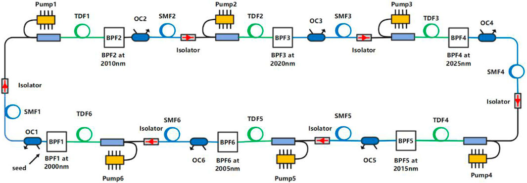
The schematic diagram of the six-wavelength laser system is shown in Figure 1. The optical pulses transmit in a single ring cavity to realize the conversion between different wavelengths and the output of multi-wavelength pulses. The Mamyshev cavity consists of six Mamyshev regenerator arms, and each arm consists of a thulium-doped fiber (TDF) with anomalous dispersion, a band-pass filter (BPF), and an output coupler (OC). The output-input coupling ratio from OC1 to OC6 is 2:8. A single-mode fiber (SMF) with anomalous dispersion and an optical isolator are placed between each regenerator. Each Mamyshev regenerator in the cavity works at a different wavelength, and the nonlinear effect of the fiber is used to broaden the spectrum of the optical pulse. The broadened spectrum covers the next wavelength to be switched, and then the filter is used to accomplish switching between the two bands, which achieves multiple wavelengths output in a single-ring cavity. The isolator is not only used to ensure single-direction transmission but also to prevent the formation of local continuous laser due to reflection at the node, especially when using non-fiber components with collimators (such as filters). SMF is used to simulate the tail fiber between regenerators (As shown in Figure 1, the six sections of TDF, labeled TDF1-TDF6, have lengths of 1 m each, and the six sections of SMF, labeled SMF1-SMF6, have lengths of 0.1 m each. The total length of the laser system is 6.6 m. In the numerical model, the filters and OC are idealized components; therefore, the total length of the laser system in the model is composed of six sections of TDF and SMF.).
The pulse wavelengths in the fiber of the six-stage Mamyshev regenerator are 2000nm, 2010 nm, 2020 nm, 2025 nm, 2015 nm, and 2005 nm. The external seed pulse evolves in the cavity and finally realizes the synchronous output of the six-wavelength pulses.
The fiber parameters are derived from commercial fibers. The gain fiber is thulium-doped fiber of Nufern SM-TSF-9/125, and the single-mode fiber is SMF-28. The fiber parameters are shown in Table 1 and Table 2. The gain coefficient g0 of the TDF is 6.9 m−1, the gain bandwidth is 80 nm [29], and the saturation energy is 2 nJ. From BPF1 to BPF6 are Gaussian filters with a bandwidth of 6.8 nm.
To simulate the propagation of the pulses in the fiber, the well-known generalized nonlinear Schrödinger equation was used. This includes the effects of attenuation, frequency dependent gain, dispersion, self-steepening, optical shock, and the Raman response [30–32]: (The dispersion and nonlinear coefficients are shown in Tables 1, 2)
The profile of the gain spectrum was assumed to be Gaussian. The saturation of the gain fiber was also considered, and thus the gain coefficient in the frequency domain is:
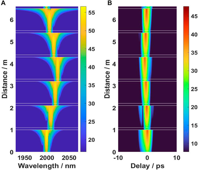
where Epulse is pulse energy, Esat is the saturation energy (2 nJ), ω0 is the reference frequency for 2000 nm, and ωb is frequency for gain bandwidth (for 80 nm bandwidth, ωb = 40). The time domain and spectrum of pulse transmission in the laser system under stable state are shown in Figure 2. The seed pulse used to start the laser is a chirpless Gaussian pulse with 36 W peak power, 2000 nm center wavelength, and 0.24 ps pulse width. In the simulation, the pulses reach a stable state after 3 cycles in the laser. The pulse time-domain evolution of the six-wavelength laser system is shown in Figure 3. The main reason for the laser to reach a stable state quickly is the powerful pulse-shaping ability of the Mamyshev regenerator. The pulses in the laser system are converted to each other at different wavelengths, and finally, the optical pulses at 2010 nm, 2020 nm, 2025 nm, 2015 nm, 2005 nm, and 2000 nm are output stably.
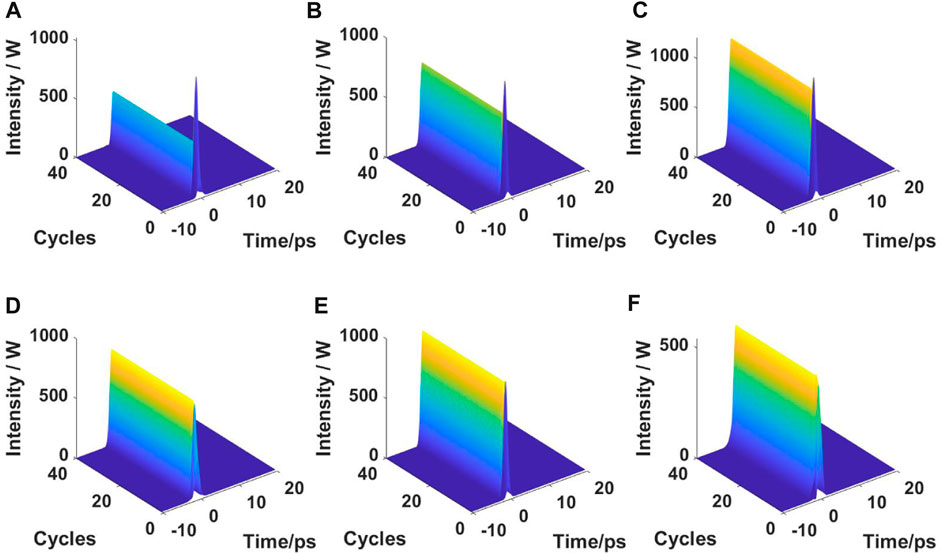
FIGURE 3. Intracavity pulse time domain evolution map in six-wavelength system. The central wavelengths of the six wavelengths are (A) 2000, (B) 2010, (C) 2020, (D) 2025, (E) 2015, and (F) 2005 nm.
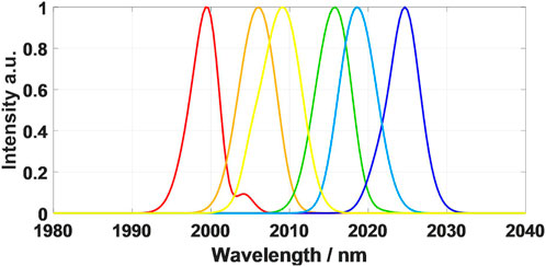
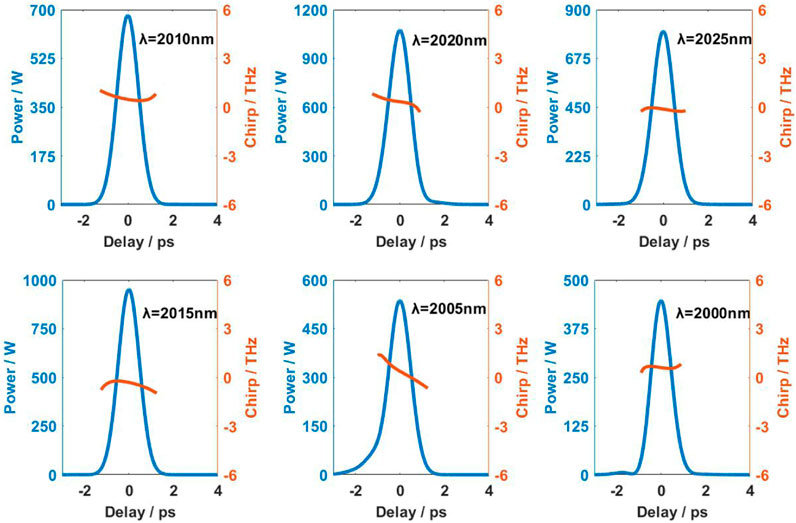
The output of the six-wavelength time domain pulse, spectrum, and time-frequency diagram are shown in Figure 4, Figure 5, and Figure 6. After the TDF parameters are properly selected, the BPF filtering position is at the flat part of the pulse broadening spectrum, which can make the laser run stably. Under other fiber lengths, it is necessary to adjust the relevant parameters of TDF and the filtering position of BPF to achieve stable output pulses of the system.
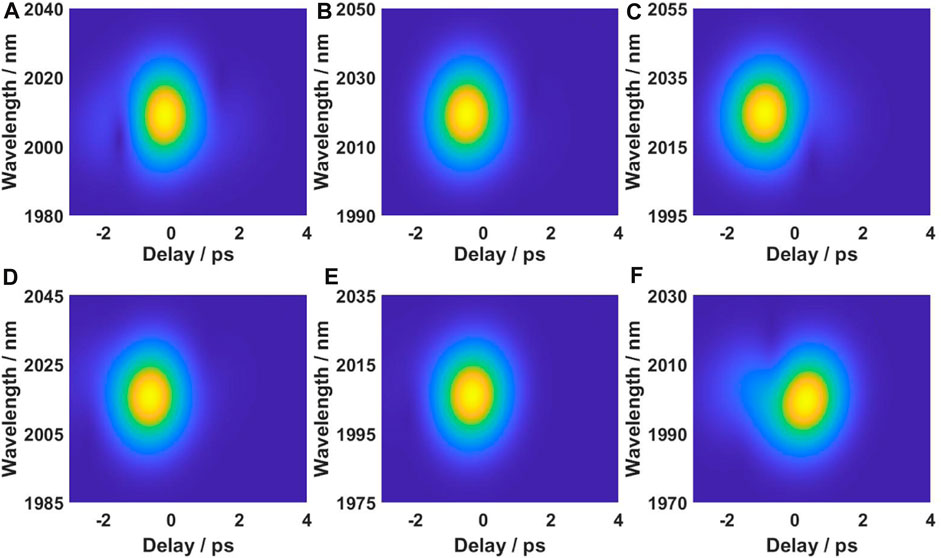
FIGURE 6. Six-wavelength time-frequency diagram. The central wavelengths of the six wavelengths are (A) 2010, (B) 2020, (C) 2025, (D) 2015, (E) 2005, and (F) 2000 nm.
The laser system in the steady state can obtain pulses with the same repetition rate and approximately linear chirp from the output of the OC. The peak power and pulse width of the pulses are shown in Table 3. The length of the laser ring cavity is 6.6 m, corresponding to a repetition rate of about 31.3 MHz.
2.2 Design principles and stability characteristics
The main principle of the Mamyshev cavity formed by cascaded Mamyshev regenerators is using nonlinear effects to broaden the spectrum to cover the target wavelength, then achieving pulse regeneration by filtering. The spectrum obtained by this nonlinear broadening is not very flat. In order to make the laser more stable, it is usually necessary to set the parameters of the gain fiber reasonably and make the filtering position of BPF located at the flat part of the broaden pulse spectrum. As a gain fiber, the ytterbium-doped fiber in 1-μm band and the erbium-doped fiber in 1.5-μm band are normal dispersion, while the thulium-doped fiber in 2-μm band is anomalous dispersion. Compared with the 1-μm and 1.5-μm bands, the pulse broadened spectrum in the 2-μm Mamyshev cavity is more rugged (Figure 7; Supplementary Figure S1), so it is significant to study the stability of the laser system.
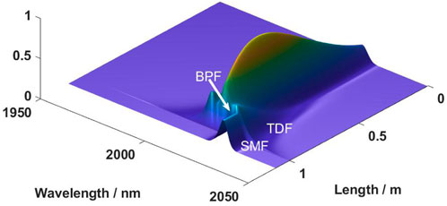
FIGURE 7. Pulse spectra evolution before and after the BPF (The spectral evolution plots for all six wavelengths can be found in Supplementary Figure S1.
The stability of the laser system can be comprehended by studying its energy transfer function (ETF) or power transfer function (PTF) [33]. Figure 8 is a schematic diagram showing how to analyze the laser output characteristics through the transfer function curve. We use the research method for one-dimensional mapping in the field of nonlinear dynamics to analyze the output and stability of the laser. (For details, please refer to our previous article [34]). We know that the laser is a feedback system, and the pulses of the mode-locked laser circulate again and again in the laser cavity. The transfer function describes the relationship between a given pulse and the pulse obtained after completing one cycle of the cavity (That is, disconnect the ring-shaped laser from a certain point, and then inject a pulse from that point to observe the output pulse that returns to that point after passing through the laser cavity.). Figure 8 uses the horizontal axis to represent the peak power of input pulses and the vertical axis to represent the peak power of output pulses. These two values are analogous to “xn” and “xn+1” in one-dimensional mapping systems commonly studied in nonlinear dynamics [35]. The well known cobweb diagram for studying the logistic map is also based on this approach. This enables us to utilize this nonlinear dynamics research method to analyze the laser’s output and stability. For example, the typical PTF curve is shown in Figure 8 [28]. The PTF curve of a stable laser system has two intersections with Pin = Pout. It can be seen that the peak power of the input pulse which is lower than point A will return to zero after multiple cycles in the cavity; when the peak power of the seed pulse injected into the laser is higher than point A, the pulse will gradually approach point B after evolution in the laser system, and finally stabilize at point B.
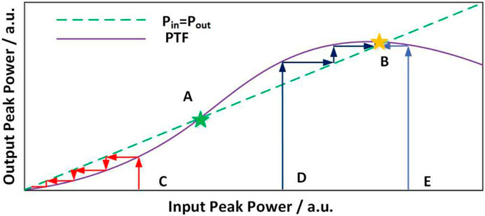
FIGURE 8. Peak power transfer function of ring fiber laser system [28].
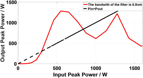
The laser ring cavity is disconnected between SMF1 and OC1, and the normalized output pulse is injected into the input of the system breakpoint. The peak power of the pulse obtained at the output of each breakpoint is recorded. The curve drawn in the coordinate diagram is the PTF curve of the Mamyshev cavity. As shown in Figure 9, the intrinsic pulse peak power of the laser system is about 0.83 kW which is the second intersection point of the PTF curve and Pin = Pout.
2.3 Influence of the filter bandwidth
The change of the filter bandwidth in the Mamyshev cavity will lead to the change of the time domain and frequency domain profile of the optical pulse after filtering, and then affect the amplification and spectrum broadening process of the gain fiber and the single mode fiber, which will affect the stability of the laser system.
As shown in Figure 10, when the filter bandwidth increases from 6.8 nm to 7.2 nm, the laser system can still reach a stable state, and the peak power of the intrinsic pulse is comparable, but the fluctuation of the PTF curve is acuter as the filter bandwidth increases. If the filter bandwidth continues to increase, the laser system will not be able to output a stable pulse. When the filter bandwidth is further reduced from 6.8 nm, the gain in the laser system will be less than the loss, the pulse will eventually disappear after evolution in the cavity, and the system will stop oscillating. It can be seen that compared with the 1-μm band, lasers working in the 2-μm band have more stringent requirements on the filter bandwidth, and the working range of the filters is significantly smaller. This is a problem that must be paid attention to in the design and use of 2-μm lasers. In actual use, it is recommended to use a tunable filter, which can be fine-tuned according to the actual situation to meet the operating conditions of the laser.
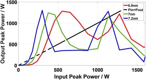
FIGURE 10. Peak power transfer function of the Mamyshev laser system with different filter bandwidths.
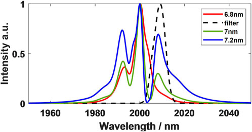
From the pulse broadened spectrum (The spectral intensity normalized to the peak value.) of the laser system in Figure 11, the reason for the change of the PTF curve can be obtained. The increase of the filter bandwidth makes the pulse broadened spectrum at the filtering position become uneven. The rugged broadened spectrum eventually leads to the fluctuation of the PTF curve and poor system stability.
2.4 Influence of the SMF length in the cavity
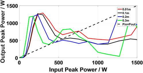
The change of SMF length in the cavity will change the stability of the system, so it is necessary to research the influence of SMF length on the stability of the system by PTF curve. Figure 12 is the input-output PTF diagram of the six-wavelength system with different SMF lengths. The laser system can reach a stable state under four SMF lengths. With the increase of SMF length, the PTF curve shows an overall downward trend, and the fluctuation of the PTF curve is more intense.
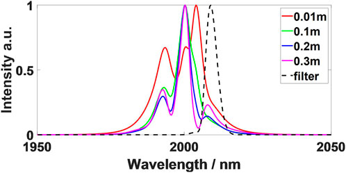
Meanwhile, the width of the pulse broadened spectrum gradually decreases, as shown in Figure 13. In this process, the peak power of the intracavity pulse decreases, and the nonlinear spectrum broadening of the pulse reduces, which can induce the flat position of the pulse broadened spectrum to deviate from the filtering position. Therefore, the length of the SMF affects the stability of the laser system by the position of offset filtering.
2.5 Influence of the output coupler
To investigate the influence of couplers on the output characteristics of the laser, we conducted calculations for the output characteristics of all wavelengths of the laser under various coupling ratios. As depicted in Figure 1, the laser system comprises six couplers (OC1∼OC6). We only adjusted the coupling ratio of OC1, while maintaining the coupling ratios of the other five couplers (OC2∼OC6) at a constant value (in/out = 80/20). This approach was adopted to facilitate a more comprehensive analysis to observe and compare the impact on the output at each wavelength when a coupler in the system changes.
Figure 14 presents output and intracavity peak Power of OC1 (2000 nm), OC5 (2015 nm) and OC6 (2005 nm) under different output coupling ratios of OC1. This illustrates the variation in pulse output peak power for this stage and the last two stages as the OC1 coupling ratio changes. (In the Supplementary Tables S1, S2 provide the peak pulse power and pulse width inside the laser cavity for all six wavelengths under different coupling ratios.) The variation in the output coupling ratio at OC1 has a notable and direct impact on the output power at OC1 (2000 nm), while the influence on other wavelengths is minimal, with no significant changes observed in pulse peak values or pulse widths (Table 4; Supplementary Tables S1, S2).
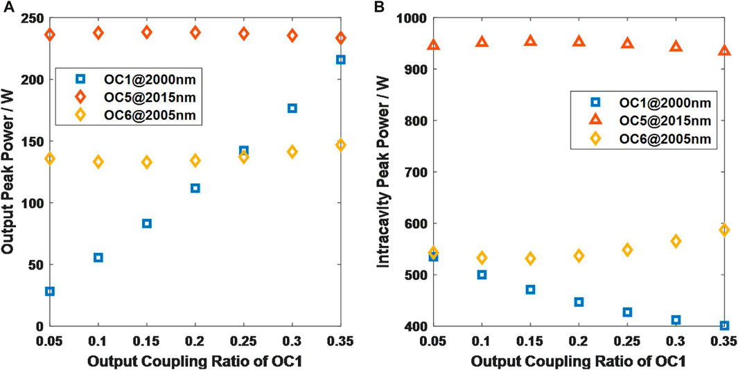
FIGURE 14. (A) Output and (B) intracavity peak power of OC1 (2000 nm), OC5 (2015 nm) and OC6 (2005 nm) under different output coupling ratios of OC1.

TABLE 4. The intracavity peak power of the six-wavelength under different output coupling ratios of OC1.
The stability of the intra-cavity power is primarily attributed to the implementation of wavelength switching through nonlinear broadening and offset filtering, where the filter selectively extracts the spectrum within the widened filter bandwidth. When the pulse power within the cavity ensures sufficient spectral broadening, variations in power have a minimal impact on the subsequent stages. While an increase in the output coupling ratio at OC1 results in a reduction of power retained within this coupler, its influence on the subsequent stage remains relatively modest within a certain range. Of course, excessively increasing the output coupling ratio can lead to a significant reduction in the pulse power retained within the cavity after passing through this coupler. Consequently, the spectral broadening becomes too narrow to cover the offset filter of the subsequent stage, causing the laser to cease functioning. We observed that when the output coupling ratio at OC1 exceeds 35%, the laser cannot operate properly.
3 Conclusion
In this paper, a 2-μm six-wavelength synchronous ultrashort pulse fiber laser based on Mamyshev regenerator is studied. The output of six-wavelength synchronous pulses is realized by using multi-stage cascade Mamyshev regenerator with anomalous dispersion. The principle is nonlinear spectral broadening and offset filtering to realize the regeneration of different wavelength pulses. There are six Mamyshev regenerator arms in the ring cavity laser, and each arm has a respective gain fiber and filter corresponding to a different wavelength. Therefore, there is no interference and gain competition between multiple wavelengths in the cavity, and the system does not require additional synchronization devices. Six-wavelength pulses with the same repetition rate are naturally synchronous and coherent. In addition, the influence of filter bandwidth and SMF length on system stability is researched by the PTF curve because of the fluctuation of the spectrum after optical pulse broadening. The pulse broadened spectrum in fiber lasers with anomalous dispersion usually fluctuates greatly, which has a great challenge for the design of multi-wavelength Mamyshev lasers with a given wavelength. Adjusting the appropriate parameters to make the offset filter position at the flat position of the broadened spectrum is a necessary condition for the stable operation of the system.
Data availability statement
The original contributions presented in the study are included in the article/Supplementary Material, further inquiries can be directed to the corresponding author.
Author contributions
RG: Writing–original draft. YG: Writing–review and editing. LP: Writing–review and editing. HW: Supervision, Writing–review and editing. All authors listed have made a substantial, direct, and intellectual contribution to the work and approved it for publication.
Funding
The authors declare financial support was received for the research, authorship, and/or publication of this article. This work was supported by the National Natural Science Foundation of China (Nos. 62221001 and 62235003).
Acknowledgments
The authors would like to thank the editors and reviewers for their efforts in supporting the publication of this paper.
Conflict of interest
The authors declare that the research was conducted in the absence of any commercial or financial relationships that could be construed as a potential conflict of interest.
Publisher’s note
All claims expressed in this article are solely those of the authors and do not necessarily represent those of their affiliated organizations, or those of the publisher, the editors and the reviewers. Any product that may be evaluated in this article, or claim that may be made by its manufacturer, is not guaranteed or endorsed by the publisher.
Supplementary material
The Supplementary Material for this article can be found online at: https://www.frontiersin.org/articles/10.3389/fphy.2023.1273027/full#supplementary-material
References
1. Xu Z, Yu CB, Huang W, Chen DD. Tunable multi-wavelength Er-doped fiber laser based on a fiber taper. J Opt (2018) 20(8):085701. doi:10.1088/2040-8986/aacaa2
2. Luo X, Tuan TH, Saini TS, Nguyen HPT, Suzuki T, Ohishi Y. Spacing-adjustable multi-wavelength erbium-doped fiber laser using a fiber Michelson interferometer. Appl Phys Express (2018) 11(8):082501. doi:10.7567/apex.11.082501
3. Han M, Li X, Zhang S, Han H, Liu J, Yang Z. Tunable and channel spacing precisely controlled comb filters based on the fused taper technology. Opt Express (2018) 26(1):265–72. doi:10.1364/OE.26.000265
4. Othonos A. Probing ultrafast carrier and phonon dynamics in semiconductors. J Appl Phys (1998) 83(4):1789–830. doi:10.1063/1.367411
5. Brian GS, Freudiger CW, Jay R, Stanley CM, Holtom GR, Xie XS. Video-rate molecular imaging in vivo with stimulated Raman scattering. Science (2010) 330(6009):1368–70. doi:10.1126/science.1197236
6. Freudiger CW, Yang W, Holtom GR, Peyghambarian N, Xie XS, Kieu KQ. Stimulated Raman scattering microscopy with a robust fibre laser source. Nat Photon (2014) 8(2):153–9. doi:10.1038/nphoton.2013.360
7. Yang K, Shen Y, Ao J, Zheng S, Hao Q, Huang K, et al. Passively synchronized mode-locked fiber lasers for coherent anti-Stokes Raman imaging. Opt Express (2020) 28(9):13721–30. doi:10.1364/OE.389728
8. Yoshitomi D, Zhou X, Kobayashi Y, Takada H, Torizuka K. Long-term stable passive synchronization of 50 µJ femtosecond Yb-doped fiber chirped-pulse amplifier with a mode-locked Ti:sapphire laser. Opt Express (2010) 18(25):26027–36. doi:10.1364/OE.18.026027
9. Qin Y, Batjargal O, Cromey B, Kieu K. All-fiber high-power 1700 nm femtosecond laser based on optical parametric chirped-pulse amplification. Opt Express (2020) 28(2):2317–25. doi:10.1364/OE.384185
10. Hassan MT, Wirth A, Grguras I, Moulet A, Luu TT, Gagnon J, et al. Invited Article: Attosecond photonics: Synthesis and control of light transients. Rev Scientific Instr (2012) 83(11):111301. doi:10.1063/1.4758310
11. Chan HS, Hsieh ZM, Liang WH, Kung AH, Peng LH, Lai CJ, et al. Synthesis and measurement of ultrafast waveforms from five discrete optical harmonics. Science (2011) 331(6021):1165–8. doi:10.1126/science.1198397
12. Brocklesby WS, Nilsson J, Schreiber T, Limpert J, Brignon A, Bourderionnet J, et al. ICAN as a new laser paradigm for high energy, high average power femtosecond pulses. Eur Phys J Spec Top (2014) 223(6):1189–95. doi:10.1140/epjst/e2014-02172-4
13. Mourou G, Tajima T, Quinn MN, Brocklesby B, Limpert J. Are fiber-based lasers the future of accelerators? Nucl Instr Methods Phys Res SectionA Acc Spectrometers Detectors Associated Equipment (2014) 740(4):17–20. doi:10.1016/j.nima.2013.10.041
14. Bellemare A, Rochette M, LaRochelle S, Tetu M, Karasek M. Room temperature multifrequency erbium-doped fiber lasers anchored on the ITU frequency grid. J Lightwave Tech (2000) 18(6):825–31. doi:10.1109/50.848393
15. Kim SK, Chu MJ, Lee JH. Wideband multiwavelength erbium-doped fiber ring laser with frequency shifted feedback. Opt Commun (2001) 190(1):291–302. doi:10.1016/S0030-4018(01)01073-2
16. Deng YX, Zhang ZX. Multiwavelength fiber lasers with tunable multiple Brillouin frequency Shift interval. Chin J Lasers (2018) 45(5):0501005. doi:10.3788/CJL201845.0501005
17. Yamashita S, Hotate K. Multiwavelength erbium-doped fibre laser using intracavity etalon and cooled by liquid nitrogen. Elect Lett (1996) 32(14):1298. doi:10.1049/el:19960832
18. Yamashita S, Hsu K, Loh W. Miniature erbium: Ytterbium fiber Fabry -perot multiwavelength lasers. IEEE J Selected Top Quan Elect (1997) 3(4):1058–64. doi:10.1109/2944.649540
19. Graydon O, Loh WH, Laming R, Dong L. Triple-frequency operation of an Er-doped twincore fiber loop laser. IEEE Photon Tech Lett (1996) 8(1):63–5. doi:10.1109/68.475779
20. Sun GC, Li YD, Zhao M, Jin GY, Wang JB. Continuous-wave dual-wavelength operation of a diode-end-pumped Nd:GGG laser. Laser Phys (2011) 21(8):1387–9. doi:10.1134/S1054660X11150217
21. Lin HY, Hong L, Wang YP. Comparative study of CW multi-wavelength Nd:GYSGG, Nd:YAG and Nd:YVO 4 lasers at 1.3 μm. Optik - Int J Light Electron Opt (2017) 147(C):123–7. doi:10.1016/j.ijleo.2017.08.068
22. Tian HC, Song YJ, Ma CY, Hu ML, Wang QY. Timing and carrier Envelope phase synchronization from two independent femtosecond lasers. Chin J Lasers (2016) 43(08):41–8. doi:10.3788/CJL201643.0801003
23. Tian H, Song Y, Yu J, Shi H, Hu M. Optical–optical synchronization between two independent femtosecond Yb-fiber lasers with 10 –20 instability in 105 s. IEEE Photon J (2017) 9(5):1–7. doi:10.1109/jphot.2017.2756909
24. Yoshitomi D, Kobayashi Y, Takada H, Kakehata M, Torizuka K. 100-attosecond timing jitter between two-color mode-locked lasers by active–passive hybrid synchronization. Opt Lett (2006) 30(11):1408–10. doi:10.1364/OL.30.001408
25. Schibli TR, Kim J, Kuzucu O, Gopinath JT, Tandon SN, Petrich GS, et al. Attosecond active synchronization of passively modelocked lasers by balanced cross correlation. Opt Lett (2003) 28(11):947–9. doi:10.1364/OL.28.000947
26. Yoshitomi D, Kobayashi Y, Kakehata M, Takada H, Torizuka K, Onuma T, et al. Ultralow-jitter passive timing stabilization of a mode-locked Er-doped fiber laser by injection of an optical pulse train. Opt Lett (2006) 31(22):3243–5. doi:10.1364/ol.31.003243
27. Mamyshev PV. All-optical data regeneration based on self-phase modulation effect[C]. In: Optical communication. IEEE (1998). p. 475–6. doi:10.1109/ECOC.1998.732666
28. Li RH, Wei H, Qin WX, Ma ZH, Tang CT, Li B, et al. Synchronous multi-wavelength ultra-short-pulse laser with arbitrary wavelength interval. IEEE Access (2020) 8(2020):167308–18. doi:10.1109/ACCESS.2020.3023396
29. Liu J, Wang P. High-power narrow-bandwidth continuous wave thulium-doped all-fiber laser. Chin J Laser (2013) 40(1):0102001. doi:10.3788/CJL201340.0102001 CNKI:SUN:JJZZ.0.2013-01-004
30. Dudley JM, Taylor JR. Nonlinear fibre optics overview. In: Supercontinuum generation in optical fiber. 1st ed. UK: Cambridge University (2010).
32. Ilday FO, Buckley JR, Clark WG, Wise FW. Self-similar evolution of parabolic pulses in a laser. Phys Rev Lett (2004) 92(21):213902. doi:10.1103/PhysRevLett.92.213902
33. North T, Brès C. Regenerative similariton laser. APL Photon (2016) 1(2):021302. doi:10.1063/1.4945352
34. Wei H, Li B, Shi W, Zhu Z, Norwood RA, Peyghambarian N, et al. General description and understanding of the nonlinear dynamics of mode-locked fiber lasers. Sci Rep (2017) 7(1):1292–304. doi:10.1038/s41598-017-01334-x
Keywords: fiber lasers, thulium-doped fiber, synchronous multi-wavelength lasers, Mamyshev, laser mode-locking
Citation: Gong R, Geng Y, Pei L and Wei H (2023) Synchronous multi-wavelength mode-locked laser at 2-μm based on Mamyshev cavity. Front. Phys. 11:1273027. doi: 10.3389/fphy.2023.1273027
Received: 05 August 2023; Accepted: 25 September 2023;
Published: 09 October 2023.
Edited by:
Ting Feng, Hebei University, ChinaReviewed by:
Bin Yin, Ocean University of China, ChinaZhenxu Bai, Hebei University of Technology, China
Copyright © 2023 Gong, Geng, Pei and Wei. This is an open-access article distributed under the terms of the Creative Commons Attribution License (CC BY). The use, distribution or reproduction in other forums is permitted, provided the original author(s) and the copyright owner(s) are credited and that the original publication in this journal is cited, in accordance with accepted academic practice. No use, distribution or reproduction is permitted which does not comply with these terms.
*Correspondence: Huai Wei, aHdlaUBianR1LmVkdS5jbg==
 Rui Gong
 Yalin Geng
 Huai Wei