 Jianhe Zhou
 Yingxiang Xiong
 Chunhua Xue
- Guangxi Colleges and Universities Key Laboratory of Microwave Communication and Micro–Nano Photoelectric Technology, School of Electronic Engineering, Guangxi University of Science and Technology, Liuzhou, China
A novel double-layer Huygens’ unit with dual-polarized response and complete phase coverage has been proposed for highly efficient meta-lens antenna application. The designed unit is a symmetric structure in which the double-layer metallic patterns not only act as the electric dipoles but also induce the magnetic dipoles. The balance between the initial electric dipole and the induced magnetic dipole makes the impedance of the metasurface match with that of free space, thus allowing efficient transmission of electromagnetic waves. Moreover, full transmission phase shift and near-unit transmission amplitude can be achieved simultaneously by change the structural parameters of the unit. Utilizing such electromagnetic properties, a dual-polarized meta-lens consisting of 35 × 35 units with size of 161 × 161 mm2 is designed, fabricated and measured. The results exhibit its good radiation performance. The maximum gain at a frequency of 28 GHz reaches 30.8 dBi, with an aperture efficiency of 42.3%. The 3-dB gain bandwidth reaches 12.5%, covering the frequency range of 26.7–30.2 GHz. The simple structure of the designed dual-polarized metasurface, high gain and high antenna efficiency make it an important antenna engineering role.
1 Introduction
Electromagnetic (EM) waves is an important carrier of information, and the realization of free manipulation of EM waves is not only of great scientific significance, but also can be used in future Information and communication technology. In the past decade, new concepts of metamaterials and metasurfaces have been proposed to address the limitations of natural materials to manipulate EM waves. Among them, metasurfaces [1] are two-dimensional artificial microstructures that use a collection of discrete planar units to achieve exotic manipulation of EM waves by tuning their phase, amplitude, and/or polarization responses. A large number of review literature present the research progress of metasurfaces from novel physical phenomena to engineering applications [2–8].
Two types of metasurfaces, i.e., reflective and transmissive ones, are used for the manipulation of far-field radiation. Because there is no feed blocking, the transmissive metasurface is more suitable for high-gain antennas than the reflective one. Typical transmissive metasurfaces include Pancharatnam-Berry metasurfaces [9, 10] and Huygens’ metasurfaces [11], which are used for the manipulations of circularly polarized wave and linearly polarized wave, respectively. Noteworthy is the Huygens’ metasurface, whose unprecedented manipulation capabilities over transmitted EM waves is achieved through the management of electric and magnetic resonances on the surface. Consequently, it manifests a plethora of captivating physical phenomena and holds immense potential for antenna applications [12–23]. In the microwave or millimeter-wave bands, one usually utilizes a wire-loop coupling structure to stimulate Huygens’ resonance [24]. However, in the wire-loop structure, the vertically placed splitted ring used to mimic a magnetic dipole introduces extra structural complexity and fabrication challenges. Achieving EM manipulation on the simplest possible structure is still a challenge.
Recent studies have demonstrated the feasibility of achieving full transmission phase coverage in a double-layer Huygens’ metasurface, in which the pair of anti-symmetric metallic patterns not only act as the electric dipoles but also induce the magnetic dipoles [25]. The proposed design significantly simplifies the complexity of the transmissive metasurface, providing a convenient method for manipulating linearly polarized transmitted EM waves. It is worth noting that the Huygens’ metasurfaces only have single-polarized response. Huygens metasurfaces with dual-polarized response were subsequently reported, but their phase shift range was only 318° [26]. This work presents a novel design of dual-polarized Huygens’ metasurface exhibiting transmission phase coverage of 360°. Owing to its capability of full transmission phase coverage, this dual-polarized Huygens metasurface provides an efficient solution for realizing high-efficient planar lens antennas. The measurements exhibit good performance of the Huygens’ meta-lens antenna including a maximum gain of 30.8 dBi at 28 GHz (corresponding to an aperture efficiency of 42.3%) and a 3-dB gain bandwidth of 26.7–30.2 GHz (12.5%).
2 Design of Huygens’ unit cell and its EM response
The schematic structure of the Huygens’ unit is illustrated in Figure 1. It is a symmetric structure consisting of bent metallic wires, where the top and the bottom patterns are printed on the corners and the sides of unit, respectively. The dielectric substrate is chosen with a relative permittivity of εr = 2.55 and a loss tangent of tanδ = 0.0015. The size of unit is p = 4.6 mm and its height is h = 1.27 mm. The structural parameters of the bent metallic wire pattern include the fixed width of w = 0.2 mm, the gap width of d = 0.2 mm and the variable parameters of a, l, g, and s. Due to the intrinsic symmetry, the design of the unit allows for a dual-polarized response, so we only need to investigate the EM behavior in terms of y-polarization. Furthermore, in order to optimize the EM response of the unit, the parameter s is set as s = l - 0.8 mm. By adjusting these parameters, the EM response of the unit can be tuned. The simulations are performed using the full-wave simulation software CST Microwave Studio.
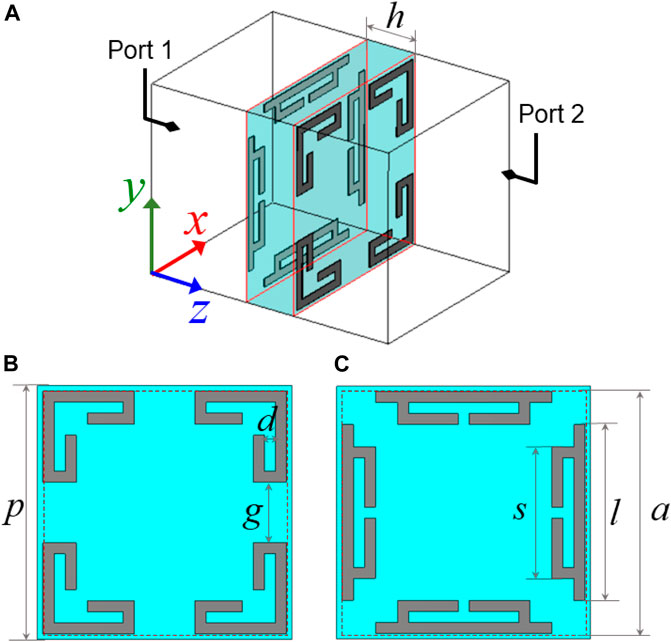
FIGURE 1. (A) Perspective view of the Huygens’ unit. (B) The top view. (C) The bottom view.
We begin our analysis by selecting the specific set of structural parameters with a = 4.4 mm, l = 3.2 mm, and g = 1.1 mm. The simulated results in Figure 2A exhibit a wideband transmission spectrum with transmission amplitudes greater than −3 dB for all frequencies above 23.5 GHz. In the wideband transmission spectrum there is a transmission peak at 24.25 GHz with the transmission phase of about 180°. Such transmission phase shows that it is a resonant transmission behavior which arises from the resonant coupling between electric and magnetic dipoles. It is noteworthy that in this unit structure, the presence of individual magnetic dipole components is absent since the metallic pattern should be regarded as an electric dipole, i.e., frequency selective surface (FSS) structure. However, the special design of the pattern makes the metallic wires of the top and bottom layers dislocated with each other. As a result, the conduction currents flowing on the metallic wires of both layers are in the opposite direction, as illustrated in Figure 2B. These conduction currents flowing in the opposite direction and the displacement currents in the substrate form a current loop. The current loop effectively constrains the induced magnetic field to the surface, which can be thought of as a magnetic dipole. Then the balance between this magnetic resonance and the electric resonance in the double-layer structure excites the Huygens’ resonance. Figure 2C presents the magnetic field distributions within the unit cell at the transmission peak of 24.25 GHz. It can be seen clearly that the magnetic field is effectively induced between the dislocated metallic wires. It should be mentioned that in this structure, it is crucial for the resonant frequencies of the top and bottom patterns to be close to the same. Otherwise, the induced magnetic resonance can at most be balanced with one of these two electric resonances, but not with the other.
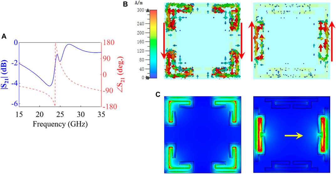
FIGURE 2. (A) The transmission amplitude and phase of the unit cell. (B) The surface currents on both sides at 24.25 GHz. (C) The magnetic field distributions of the unit cell.
As mentioned above, the EM response of this unit is able to be tuned by varying the parameters a, g and s. Here we take a two-step strategy. In the first step, we set g = 1.1+(a-4.4)×0.2 mm and l = 3.2+(a-4.4)×0.8 mm, and then vary a from 2.8 to 4.4 mm to tune the frequency response of the unit. The size of the pattern is maximized when a increases to 4.4 mm. In the second step, we set a = 4.4 mm and l = 3.2 + 0.4×(1.1-g) mm, and then vary g from 1.1 to 0.15 mm to further change the frequency response of the unit. The simulated results are illustrated in Figure 3. For the first step, the transmission amplitudes are greater than −1.86 dB and the transmission phases reach 318°. For the second step, the transmission amplitudes are greater than −1.2 dB and the transmission phases cover 33°. When combining the two steps, the available transmission phase reaches 351°, which can be considered as full phase coverage. The transmission amplitudes and transmission phases at several representative parameters are listed in Table 1.
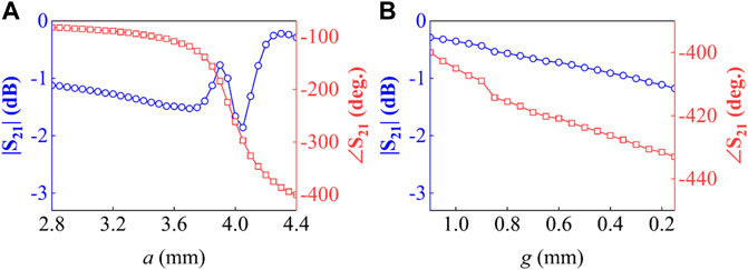
FIGURE 3. The transmission amplitudes and phases (A) when a varies from 2.8 to 4.4 mm with g = 1.1 + (a-4.4) × 0.2 mm and l = 3.2 + (a-4.4) × 0.8 mm, and (B) when g varies from 1.1 to 0.15 mm with a = 4.4 mm and l = 3.2 + 0.4 × (1.1-g) mm.
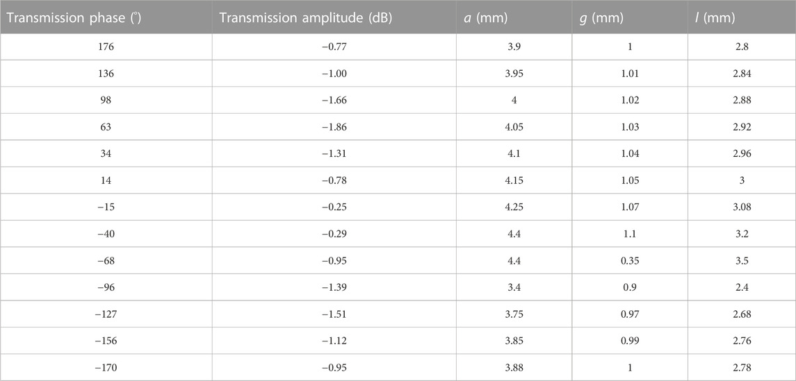
TABLE 1. The transmission amplitudes and transmission phases at some representative parameters.
3 Meta-lens antenna design, simulation and measurement
The typical application of the symmetric Huygens’ metasurface is a dual-polarized meta-lens antenna. In this antenna system, a feed source is meticulously positioned above the focal point of the planar lens. The focal length, denoted as F, represents the distance from the focal point to the metasurface. In order to realize the conversion of a spherical wave to a plane wave, it is imperative to satisfy to the specified expression when configuring the discrete phase distribution on the meta-lens as follows [25].
Where c is the speed of light in free space, f0 = 28 GHz is the working frequency, and φ(m, n) is the phase difference of the unit (m, n) with respect to the center unit. The designed dual-polarized meta-lens is an array composed of 35 × 35 units with a size of 161 × 161 mm2. The feed source is chosen as a 15 dBi standard gain horn antenna with F = 152 mm. The discrete transmission amplitudes and phases on the metasurface are shown in Figure 4. According to the transmission amplitude and phase distribution, the meta-lens is fabricated and subsequently evaluated using the experimental setup depicted in Figure 5. A microwave anechoic chamber is used for all far-field measurements.
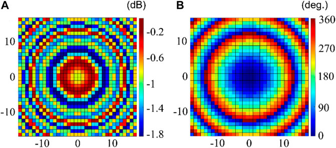
FIGURE 4. (A) The transmission amplitude and (B) the transmission phase distribution of the meta-lens.
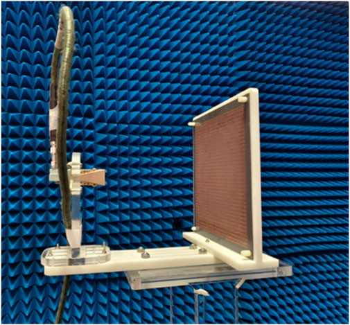
FIGURE 5. The experimental setup of the dual-polarized Huygens’ meta-lens.
The 3-D and 2-D radiation patterns of the meta-lens antenna are simulated and measured. On the one hand, to provide an intuitive visualization of the wavefront transformation based on the meta-lens designed above, a simulation of the electric field at 28 GHz is performed in Figure 6A. It can be seen that the spherical wavefront radiated from the horn feed is effectively converted to a plane wavefront after passing through the meta-lens. Overall, the meta-lens exhibits the ability to achieve a high directional beam. As illustrated in Figure 6B, the 3-D radiation pattern exhibits a narrow pencil-shaped beam in the transmission region of meta-lens. On the other hand, the simulated and measured results of 2-D radiation patterns are shown in Figures 6C, D. It can be seen that the half-power beam-width of the radiated beam is about 4.1°. The simulated and measured side lobe levels are −23 and −20 dB, respectively. For such low sidelobe levels, this error between the simulation and the measurement is acceptable, and it mainly originates from the assembly accuracy of the antenna system, such as the position and/or illumination angle of the horn feed. Moreover, the H-plane pattern is very similar to the E-plane pattern. Besides, the cross-polarization levels are −31 dB compared with the co-polarization. The cross-polarization of the meta-lens antenna system mainly comes from the horn feed. Overall, the measured results are in good agreement with the simulated results.
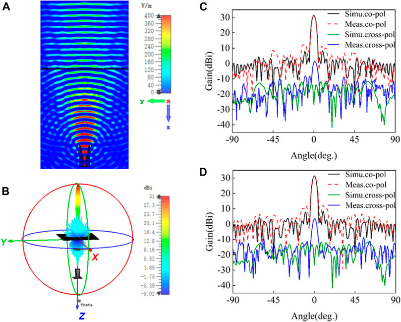
FIGURE 6. (A) The wavefront conversion characterized by tangential electric field. (B) The 3-D far-field radiation pattern. (C) The 2-D far-field radiation patterns for y-polarization and (D) for x-polarization.
Figure 7 illustrates the gain spectrum and aperture efficiency of the meta-lens antenna. The simulation results indicate that a maximum gain is obtained at 27.8 GHz with a value of 31.14 dBi, which is 16.14 dB above the horn feed source. The simulated 3-dB gain bandwidth is the frequency range of 26–29.8 GHz, corresponding to the relative bandwidth of 13.8%. These simulated results clearly showcase the outstanding focusing capability of the meta-lens. Then we measure the far-field radiation for both polarizations to determine the dual-polarization performance. For the y-polarization, the measured maximum gain appears at 28 GHz with a value of 30.8 dBi. Its 3-dB gain bandwidth ranges from 26.7 to 30.2 GHz, corresponding to a relative bandwidth of 12.5%. For x-polarization, we have observed a maximum gain of 30.6 dBi precisely at 28 GHz. Its 3-dB gain bandwidth ranges from 26.8 to 30.1 GHz, or 11.8%. The measurements for both polarizations are very close to each other and have a similar spectral shape compared to the simulation results. Therefore, the simulation results are effectively verified by the measurements. In addition, there is slight frequency shift of measurement towards higher frequencies by about 0.5 GHz compared to the simulation results. The frequency shift of gain spectrum maybe is caused by the manufacturing errors.
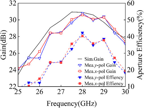
FIGURE 7. Simulated and measured gain spectrum and aperture efficiency.
In addition, the aperture efficiency can be calculated with gain G, the size of meta-lens D and the operating wavelength λ0, which satisfies the equation η = Gλ02/(4πD2)×100%. The simulated aperture efficiency reaches the maximum of 45.76% at 27.8 GHz. The y- and x-polarized measurement value reaches the maximum 42.3% and 40.3% at 28 GHz, respectively. In brief, both the simulated and measured results consistently exhibit outstanding radiation performance of the meta-lens antenna, validating its effectiveness.
The important performance indicators of the proposed meta-lens antenna with the state-of-the-art planar lens antenna are compared in Table 2. All the lens antennas mentioned in Table 2 have obtained high gain and aperture efficiency with full phase coverage. However, multilayer FSS structures are used in Ref. [27–29], which leads to complex structures and expensive manufacturing. On the other hand, the proposal of Ref. [30] has the advantage of a simple double-layer structure, but only work in the single-polarization case. In contrast, our work provides a solution to achieve a high-performance dual-polarized lens antenna with the simple structure and low manufacturing cost.
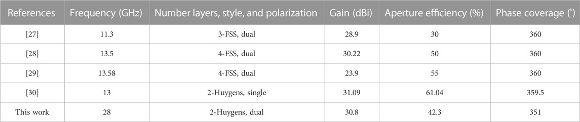
TABLE 2. Comparison of the proposed meta-lens with referenced designs.
4 Conclusion
In summary, we studied a dual-layer dual-polarized Huygens’ metasurface with full transmission phase coverage and its application of high efficient meta-lens antenna. The Huygens’ metasurface is implemented on a dielectric substrate and achieves available transmission phase coverage of 360°. When the metasurface is used for meta-lens antenna, the simulated and measured results show strong focusing capability and good radiation performance. This Huygens’ metasurface obtains complete transmission phase coverage in a simplified structure, which means low cost and easy to fabricate. The current work is concerned with the generation of highly directional fixed beams. When loaded with PIN diodes, this meta-lens antenna can be expected to be used for beam steering. Undoubtedly, it has the potential to promote more engineering applications.
Data availability statement
The original contributions presented in the study are included in the article/Supplementary Material, further inquiries can be directed to the corresponding author.
Author contributions
JZ: Funding acquisition, Methodology, Project administration, Writing–review and editing. YX: Conceptualization, Formal Analysis, Investigation, Writing–original draft. QP: Data curation, Visualization, Writing–original draft. ZB: Resources, Validation, Writing–original draft. CX: Funding acquisition, Supervision, Writing–review and editing.
Funding
The authors declare financial support was received for the research, authorship, and/or publication of this article. This work was financially supported by the National Natural Science Foundation of China under Grant 62071133, and by the Key Program of Natural Science Foundation of Guangxi Province under Grant 2019GXNSFDA245011.
Conflict of interest
The authors declare that the research was conducted in the absence of any commercial or financial relationships that could be construed as a potential conflict of interest.
Publisher’s note
All claims expressed in this article are solely those of the authors and do not necessarily represent those of their affiliated organizations, or those of the publisher, the editors and the reviewers. Any product that may be evaluated in this article, or claim that may be made by its manufacturer, is not guaranteed or endorsed by the publisher.
References
1. Yu N, Genevet P, Kats MA, Aieta F, Tetienne J-P, Capasso F, et al. Light propagation with phase discontinuities: Generalized laws of reflection and refraction. Science (2011) 334:333–7. doi:10.1126/science.1210713
2. Chen H-T, Taylor AJ, Yu N. A review of metasurfaces: Physics and applications. Rep Prog Phys (2016) 79:076401. doi:10.1088/0034-4885/79/7/076401
3. Glybovski SB, Tretyakov SA, Belov PA, Kivshar YS, Simovski CR. Metasurfaces: From microwaves to visible. Phys Rep (2016) 634:1–72. doi:10.1016/j.physrep.2016.04.004
4. Hsiao H-H, Chu CH, Tsai DP. Fundamentals and applications of metasurfaces. Small Methods (2017) 1:1600064. doi:10.1002/smtd.201600064
5. Guo Y, Pu M, Li X, Ma X, Gao P, Wang Y, et al. Functional metasurfaces based on metallic and dielectric subwavelength slits and stripes array. J Phys Condens Matter (2018) 30:144003. doi:10.1088/1361-648x/aaa84a
6. Ding F, Pors A, Bozhevolnyi SI. Gradient metasurfaces: a review of fundamentals and applications. Rep Prog Phys (2017) 81(2):026401. doi:10.1088/1361-6633/aa8732
7. Ren X, Jha PK, Wang Y, Zhang X. Nonconventional metasurfaces: from non-hermitian coupling, quantum interactions, to skin cloak. Nanophotonics (2018) 7(6):1233–43. doi:10.1515/nanoph-2018-0006
8. Asadchy VS, Rubio AD, Tretyakov SA. Bianisotropic metasurfaces: Physics and applications. Nanophotonics (2018) 7(6):1069–94. doi:10.1515/nanoph-2017-0132
9. Ding X, Monticone F, Zhang K, Zhang L, Gao D, Burokur SN, et al. Ultrathin pancharatnam–berry metasurface with maximal cross-polarization efficiency. Adv Mater (2015) 27:1195–200. doi:10.1002/adma.201405047
10. Cong L, Xu N, Han J, Zhang W, Singh R. A tunable dispersion-free terahertz metadevice with pancharatnam–berry-phase-enabled modulation and polarization control. Adv Mater (2015) 27:6630–6. doi:10.1002/adma.201502716
11. Pfeiffer C, Grbic A. Metamaterial Huygens’ surfaces: Tailoring wave fronts with reflectionless sheets. Phys Rev Lett (2013) 110(19):197401. doi:10.1103/physrevlett.110.197401
12. Jia S, Wan X, Bao D, Zhao Y, Cui T. Independent controls of orthogonally polarized transmitted waves using a Huygens metasurface. Laser Photon Rev (2015) 9(5):545–53. doi:10.1002/lpor.201500094
13. Cai T, Tang S, Wang G, Xu H, Sun S, He Q, et al. High-performance bifunctional metasurfaces in transmission and reflection geometries. Adv Opt Mater (2017) 5(2):1600506. doi:10.1002/adom.201600506
14. Chen M, Sánchez EA, Epstein A, Eleftheriades GV. Theory, design, and experimental verification of a reflectionless bianisotropic Huygens' metasurface for wide-angle refraction. Phys Rev B (2018) 97:125433. doi:10.1103/physrevb.97.125433
15. Xu H-X, Hu G, Han L, Jiang M, Huang Y, Li Y, et al. Chirality-assisted high-efficiency metasurfaces with independent control of phase, amplitude, and polarization. Adv Opt Mater. (2019) 7:1801479. doi:10.1002/adom.201801479
16. Hao WM, Deng M, Chen SQ, Chen L. High-efficiency generation of airy beams with huygens’ metasurface. Phys Rev Appl (2019) 11:054012. doi:10.1103/physrevapplied.11.054012
17. Londoño M, Sayanskiy A, Araque-Quijano JL, Glybovski SB, Baena JD. Broadband huygens’ metasurface based on hybrid resonances. Phys Rev Appl (2018) 10:034026. doi:10.1103/physrevapplied.10.034026
18. Cuesta FS, Faniayeu IA, Asadchy VS, Tretyakov SA. Planar broadband Huygens’ metasurfaces for wave manipulations. IEEE Trans Antennas Propag (2018) 66(12):7117–27. doi:10.1109/tap.2018.2869256
19. Dorrah AH, Chen M, Eleftheriades GV. Bianisotropic huygens’ metasurface for wideband impedance matching between two dielectric media. IEEE Trans Antennas Propag (2018) 66(9):4729–42. doi:10.1109/tap.2018.2851361
20. Wang Z, Ding X, Zhang K, Ratni B, Burokur SN, Gu X, et al. Huygens metasurface holograms with the modulation of focal energy distribution. Adv Opt Mater. (2018) 6:1800121. doi:10.1002/adom.201800121
21. Guan C, Wang Z, Ding X, Zhang K, Ratni B, Burokur SN, et al. Coding Huygens’ metasurface for enhanced quality holographic imaging. Opt Express (2019) 27:7108–19. doi:10.1364/oe.27.007108
22. Wang Z, Liu J, Ding X, Zhao W, Zhang K, Li H, et al. Three-dimensional microwave holography based on broadband huygens' metasurface. Phys Rev Appl (2020) 13:014033. doi:10.1103/physrevapplied.13.014033
23. Liu M, Powell DA, Zarate Y, Shadrivov IV. Huygens’ metadevices for parametric waves. Phys Rev X (2018) 8:031077. doi:10.1103/physrevx.8.031077
24. Selvanayagam M, Eleftheriades GV. Circuit modeling of huygens surfaces. IEEE Antennas Wirel Propag Lett (2013) 12:1642–5. doi:10.1109/lawp.2013.2293631
25. Xue C, Lou Q, Chen ZN. Broadband double-layered huygens’ metasurface lens antenna for 5G millimeter-wave systems. IEEE Trans Antennas Propag (2020) 68:1468–76. doi:10.1109/tap.2019.2943440
26. Xue C, Sun J, Niu L, Lou Q. Ultrathin dual-polarized huygens’ metasurface: Design and application. Ann Phys (Berlin) (2020) 532:2000151. doi:10.1002/andp.202000151
27. Abdelrahman AH, Elsherbeni AZ, Yang F. High-gain and broadband transmitarray antenna using triple-layer spiral dipole elements. IEEE Antennas Wirel Propag Lett (2014) 13:1288–91. doi:10.1109/lawp.2014.2334663
28. Abdelrahman AH, Nayeri P, Elsherbeni AZ, Yang F. Bandwidth improvement methods of transmitarray antennas. IEEE Trans Antennas Propag (2015) 63:2946–54. doi:10.1109/tap.2015.2423706
29. Liu G, Wang H -j., Jiang J -s., Xue F, Yi M. A high-efficiency transmitarray antenna using double split ring slot elements. IEEE Antennas Wirel Propag Lett (2015) 14:1415–8. doi:10.1109/lawp.2015.2409474
Keywords: Huygens’ metasurface, complete phase coverage, induced magnetism, meta-lens, dual-polarized
Citation: Zhou J, Xiong Y, Peng Q, Bin Z and Xue C (2023) A double-layer Huygens’ metasurface with complete phase coverage and its dual-polarized meta-lens antenna application. Front. Phys. 11:1271969. doi: 10.3389/fphy.2023.1271969
Received: 03 August 2023; Accepted: 12 September 2023;
Published: 22 September 2023.
Edited by:
Ben-Xin Wang, Jiangnan University, ChinaCopyright © 2023 Zhou, Xiong, Peng, Bin and Xue. This is an open-access article distributed under the terms of the Creative Commons Attribution License (CC BY). The use, distribution or reproduction in other forums is permitted, provided the original author(s) and the copyright owner(s) are credited and that the original publication in this journal is cited, in accordance with accepted academic practice. No use, distribution or reproduction is permitted which does not comply with these terms.
*Correspondence: Yingxiang Xiong, xiongyx913@163.com