 Andrii S. Savchenko
 Vladyslav M. Kuchkin
 Filipp N. Rybakov4
 Nikolai S. Kiselev
95% of researchers rate our articles as excellent or good
Learn more about the work of our research integrity team to safeguard the quality of each article we publish.
Find out more
ORIGINAL RESEARCH article
Front. Phys. , 09 June 2023
Sec. Condensed Matter Physics
Volume 11 - 2023 | https://doi.org/10.3389/fphy.2023.1223609
This article is part of the Research Topic Nucleation and Stability of Exotic Solitons in Condensed Matter View all 6 articles
In magnetic multilayers with perpendicular anisotropy, the competition of short-range and long-range interactions gives rise to the stability of cylindrical magnetic domains, also known as magnetic bubbles. The presence of Dzyaloshinsky-Moriya interaction induced by asymmetric interfaces between magnetic and nonmagnetic layers may lead to the formation of cylindrical bubble domains with Neel-type domain walls across the whole thickness of the multilayer. Such domain walls produce no contrast in Lorentz TEM under the normal incidence of the electron beam to the film. The latter is often used as an argument for the presence of Dzyaloshinskii-Moriya interaction in the system. Here we show that in magnetic multilayers, the absence of the Lorentz TEM contrast might also have another origin. In particular, in the absence of interfacial Dzyaloshinskii-Moriya interaction and weak interlayer exchange coupling, the magnetic bubbles might have Bloch-type domain walls of alternate chirality in adjacent layers. Such domain walls also do not produce magnetic contrast in Lorentz TEM at normal incidence of the electron beam. We show that, in the absence of interlayer exchange coupling, the magnetic bubble domains with the domain walls of fixed and alternate chirality have nearly identical energies and can coexist in the same range of magnetic fields. Using the geodesic nudged elastic band method, we prove that these states are separated by finite energy barriers. Furthermore, we demonstrate that magnetic multilayers with only dipolar coupling, besides the magnetic bubbles with nontrivial topology in all layers, can accommodate solutions with trivial topology within the internal layers.
Topological solitons are localized in space, finite energy field configurations that can be attributed to a certain homotopy class [1]. Topological magnetic solitons are such configurations of magnetization field, which are usually stabilized by the competition between short-range interactions. For instance, chiral magnetic skyrmions are the solitons stabilized by the competition of Heisenberg exchange, Dzyaloshinskii-Moria interaction (DMI) [2]; [3] and potential energy term composed of, e.g., Zeeman energy term or magnetocrystalline anisotropy [4]; [5]; [6]. Another example is magnetic hopfions in frustrated magnets which are stabilized by the competition of Heisenberg exchange interactions at different distances [7]; [8]; [9]. Magnetic bubbles are a distinct type of topological magnetic solitons that are stabilized by the long-range dipole-dipole interaction. In particular, in thin films, the stabilization of magnetic bubbles is determined by the competition between demagnetizing fields, uniaxial magnetocrystalline anisotropy, external magnetic field, and exchange interaction [10]; [11]. Magnetic bubbles were experimentally discovered already in the late 1950s in the films of orthoferrites, MFeO3, where M is a rare Earth metal. In 1960, Kooy and Enz provided comprehensive studies and the first theoretical descriptions of magnetic domains in terms of the micromagnetic model [12]. In 1967, Bobeck highlighted the potential of using magnetic bubbles for various applications, including memory devices [13]. The first commercial product incorporating bubble domain memory chips was released in 1977. For a decade, bubble domain memory occupied its niche on the market. In particular, bubble domain memory was widely used in systems operating in harsh environments, such as those with high vibration. In the late 1980s, however, significant advances in hard disk drive technology and semiconductor chips pushed bubble memory out of the market.
Recently, the interest in nonvolatile memory devices based on magnetic solitons, such as magnetic bubbles, skyrmions, and hopfions, has been renewed [14]; [15]. Perpendicular anisotropy multilayers composed of magnetic materials (e.g., Co, Ni, Fe, or Gd) and nonmagnetic materials (e.g., Pt, Pd, MgO, Ru, Ir) are the most promising and most common systems for studying magnetic bubbles nowadays [16]; [17]; [18]; [19]; [20]; [21]; [22]; [23]. Such multilayers are typically fabricated using magnetron sputter deposition or molecular beam epitaxy. The individual layers typically have a thickness of about 1 nm, and the number of layers can vary widely depending on the purpose of the study.
Magnetic force microscopy (MFM) and Lorentz transmission electron microscopy (LTEM) are two commonly used and complementary techniques for observing magnetic bubbles in multilayers. MFM primarily provides information about the out-of-plane component of the induction field at a certain distance above the sample. On the other hand, LTEM offers insight into the in-plane component of the induction field averaged over the entire thickness of the sample. LTEM is particularly useful for detecting magnetic bubbles with Neel-type domain walls in magnetic multilayers that exhibit DMI induced by broken inversion symmetry at the interfaces between magnetic and nonmagnetic layers [24]. In the literature, these magnetic bubbles are often referred to as bubble skyrmions, or skyrmion bubbles [25]. When the electron beam is incident perpendicular to the film plane, bubble skyrmions do not produce any contrast in LTEM. They become visible only when the sample is tilted relative to the electron beam [26]; [27]; [28]; [29]; [30]. This distinct behavior of LTEM contrast often serves as a criterion for identifying the presence of bubble skyrmions since ordinary bubble domains with Bloch-type domain walls produce contrast at any tilt angle [11]. Here we show that the Neel-type domain walls are not the only explanation for this behavior in LTEM. Specifically, we examine a model of magnetic multilayers lacking interfacial DMI (iDMI), where the interaction between individual magnetic layers occurs through interlayer exchange coupling (IEC) and demagnetizing fields. More precisely, we investigate three scenarios of IEC: ferromagnetic
We consider a micromagnetic model of the magnetic multilayer with the following Hamiltonian:
where mi (x, y) represents the local magnetization unit vector field in the ith magnetic layer, Ms is the saturation magnetization,
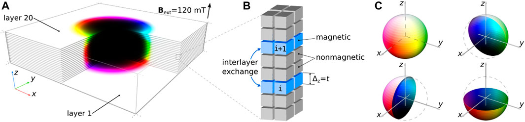
FIGURE 1. (A) Stable configuration of magnetic bubble domain in multilayer obtained in the micromagnetic simulations. Only magnetic layers are shown. One-quarter of the domain is hidden to show the magnetization in the inner part of the simulated domain. (B) Schematic illustration of the finite difference mesh of cuboids with identical size. The magnetic layers are separated by the two layers of nonmagnetic material and, besides dipole-dipole interaction, are coupled by interlayer exchange coupling (IEC) implemented in the mumax script by means of the effective custom field. (C) The standard color code for magnetization: white and black colors correspond to magnetization parallel and antiparallel to the z-axis, and red-green-blue colors correspond to the xy-component of magnetization.
The main results presented in this work were obtained by direct energy minimization performed in Mumax [32] code and Excalibur code [33] for crosschecking. We utilized the Excalibur code to carry out energy minimization of the Hamiltonian (1) in the Coulomb gauge [34]. On the other hand, the Mumax code formulates the magnetostatic problem without employing the magnetic vector potential following different approach [31]. Nevertheless, it yields results remarkably similar to those obtained from the Excalibur code. In particular, in the case of periodic boundary conditions, increasing the number of periodic images (copies) of the simulated domain improves the agreement with the Excalibur code. The LTEM images of corresponding magnetic textures were calculated with the Excalibur code.
A representative example of a magnetic bubble in a multilayer composed of twenty magnetic layers is shown in Figure 1A. The standard color code used to represent the magnetization vector directions is explained in Figure 1C. Here we set weak ferromagnetic interlayer exchange coupling,
Figure 1B illustrates the finite difference scheme employed in our calculations. In this scheme, each magnetic layer is represented by a single layer of cuboids, while the nonmagnetic layers consist of two cuboids. Thereby, the ratio of magnetic to nonmagnetic layer thickness is 0.5. The choice of this geometry is motivated by the previous studies on magnetic multilayers with asymmetric interfaces, where the magnetic layers are typically thinner than nonmagnetic layers. For instance, Moreau-Luchaire et al. [24] investigated [Ir (1 nm)/Co(0.6 nm)/Pt (1 nm)]10 multilayers, where the magnetic to nonmagnetic layer thickness ratio was 0.3. In another system studied by Soumyanarayanan et al. [35], [Ir (1 nm)/Fe (t1)/Co(t2)/Pt (1 nm)]N, the ratio varied between 0.2 and 0.6, with t1 ∈ [0 nm, 0.6 nm] and t2 ∈ [0.4 nm, 0.6 nm]. In Ref. [27], the authors studied [Pt (3 nm)/Co(x nm)/Ta (2 nm)]11 multilayer with x = 2.05, 2.1, and 2.15, where the ratio of magnetic to nonmagnetic layer thickness varied between 0.41 and 0.43. Since micromagnetic calculations are performed on a regular grid, we set the magnetic to nonmagnetic layer thickness ratio to 1/2 in our simulation. It is worth noting that a specific layer thickness ratio does not significantly impact the results presented below if the thickness of the nonmagnetic layers remains finite.
Figure 2 shows four distinct magnetic bubbles that are stabilized in a multilayer consisting of 20 magnetic layers. These magnetic bubbles exhibit diverse domain wall profiles while maintaining almost identical sizes. Furthermore, all of them are stable under the same perpendicular field of Bext = 120 mT. In all four cases, we use the same Ms and
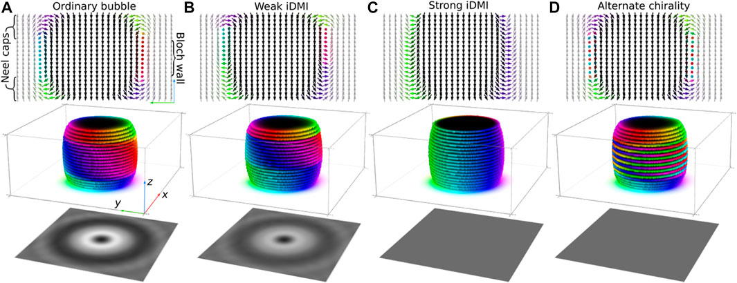
FIGURE 2. Representative examples of magnetic bubble domains in a multilayer with different structures of the domain wall. The material parameters used in the simulations in (A–D) are provided in the main text. Note, the parameters in (A, D) are identical. The upper panel shows magnetization in the yz-plane of the sample. The middle panel shows the cuboids with mz ≤ 0 and illustrates the shape of the bubble domains. The bottom panel shows LTEM images of corresponding magnetic textures calculated for normal incident electron beam parallel to the z-axis.
The magnetic bubble shown in Figure 2A represents a typical magnetic bubble in the system without iDMI. Within all middle layers, the magnetization exhibits Bloch-like modulations with identical chirality. Here we show the magnetic bubble with right-handed chirality in the domain wall. However, both states with left-handed and right-handed chirality have equal energy. Note, the chirality can be rigorously defined by the sign of so-called Rogers’s mean geodesic torsion, ρ(r) = m ⋅ (∇ ×m), see Ref. [36] and corresponding citations there. Near the surface, the magnetization forms what is known as Néel caps [37]; [38], where the magnetization aligns with the direction of the demagnetizing field. It is important to note that the magnetization in Néel caps can point either inward or outward, depending on the polarity of the magnetic bubble. However, at the top and bottom surfaces, the magnetization always points in opposite directions. Specifically, when a bubble is embedded in a ferromagnetic state along the z-axis, and its core is magnetized in the opposite direction, the top Néel cap has inward-pointing magnetization, while the bottom Néel cap has outward-pointing magnetization as seen in Figure 2A.
In the presence of weak iDMI (
The most interesting configuration has a magnetic bubble depicted in Figure 2D. Similar to the bubble depicted in Figure 2A, the domain wall has Néel caps near the surfaces and Bloch-type domain walls in the middle layers. However, contrary to the case in Figure 2A, the chirality of the Bloch domain walls alternate in adjacent layers. It is worth emphasizing that the configurations depicted in Figures 2A,D are obtained at identical conditions, without iDMI and IEC
The bottom row of images in Figure 2 shows the over-focus LTEM images calculated for each magnetic texture, assuming that the electron beam is perpendicular to the film plane. The magnetic bubbles with fixed chirality of the Bloch domain walls in all layers produce a strong contrast. In the case of weak iDMI, the contrast is getting a bit weaker but still can be well seen even at normal incidence of the electron beam. On the contrary, for magnetic bubbles depicted in Figures 2C,D, the LTEM contrast is entirely absent.
In Figure 3, we provide the over-focus LTEM images for the same four types of magnetic bubbles shown in Figure 2 but at different tilt angles of the electron beam. Note that the contrast for the magnetic bubble with alternate chirality in the domain wall in Figure 3D is nearly identical to that for bubble skyrmion in Figure 3C. A small difference between images Figures 3C,D is the matter of fixed defocus distance, which in our calculations is set to 400 μm in all four cases. In practice, the defocus distance might vary up to a few millimeters in order to achieve the highest contrast [29]; [30]. The resulting pattern in the LTEM image might also change with the defocus distance. More importantly that in both cases, the contrast appears only at a non-zero tilt of the electron beam.
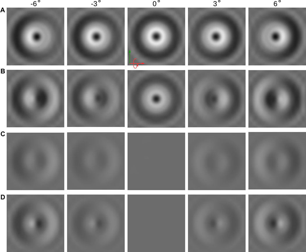
FIGURE 3. Lorentz TEM images of magnetic bubbles with different domain wall structures at different tilt angles of the incident electron beam. Each row of images corresponds to a particular type of bubble domain depicted in Figure 2: (A) normal bubble with fixed chirality across all internal layers, (B) bubble domain in the presence of weak iDMI, (C) bubble domain at strong iDMI, and (D) bubble domain with alternate chirality across the internal layers.
The absence of contrast in the case of alternate chirality domain walls and at normal incidence of the electron beam can be explained as follows. It is well known that the magnetic babbles of opposite chirality produce the opposite contrast in LTEM images. The examples of the images with inverse contrast for magnetic bubbles with opposite chirality can be found in the prime book on magnetic bobbles by Malozemoff and Slonczewski [11]. The superposition of the bubbles of identical size but opposite chirality on top of each other leads to the compensation of the LTEM contrast. It is worse to emphasize that the complete compensation of the contrast occurs only when there is an equal number of layers with left-handed and right-handed chirality. Thus in the case of an odd number of magnetic layers, it is reasonable to anticipate that the LTEM contrast will persist in the case of alternate chirality. However, the intensity of the contrast, in this case, is too weak to be seen in the background of the noise appearing due to the granular structure of the sputter-deposited multilayers [30]. Moreover, as will be shown below, besides the stable solution with alternate chirality (when each next layer has a chirality opposite to the previous one), for
In the case of FM IEC, the configuration depicted in Figure 2A and Figure 3A has the lowest energy, while in the case of weak AF IEC, the lowest energy has the magnetic bubble shown in Figure 2D and Figure 3D. The direct evidence for the AF IEC in the multilayer systems with asymmetric interfaces was provided earlier by Lau et al. [39]. In this work, the authors studied [Ir/Co/Pt]3 multilayers with varying thicknesses of Ir and Pt layers. They found that for a wide range of [Ir/Pt] interface thicknesses, up to 1.5 nm, the system exhibits an AF IEC.
The direct observation of the domain walls with alternate chirality has been recently reported in {[Pt/Co]12/Ru}4 multilayers [40]. In this work, the presence of alternate chirality domain walls has been explicitly confirmed by direct observation with LTEM and complementary vector magnetometry measurements [41]. In these multilayers, a weak AF IEC (
Taking into account the oscillatory behavior of IEC and its decay with the nonmagnetic layer thickness, it is reasonable to assume that for 2-nm-thick interfaces between magnetic layers, the IEC might become negligibly small [18]. For instance, in Ref. [42], it was demonstrated that the IEC between Py layers, mediated by the Pt layer, reduces to zero when the Pt interlayer thickness approaches 2 nm. As follows from our calculations in the case of an exchange decoupled system,
To prove that the states with fixed and alternate chirality are separated by the finite energy barrier, we calculated the minimum energy path (MEP) between these states using the geodesic nudged elastic band (GNEB) method [43,44]. The results of these calculations are provided in Figure 4. The initial state of ordinary babble with fixed chirality is shown in Figure 4A, and the final state for the bubble with alternate chirality is shown in Figure 4C. In this calculation, we used the multilayers with twelve magnetic layers. Note that Néel caps occupy four top and four bottom layers, and there are only four internal layers with Bloch modulations. Thereby, the transition into the alternate chirality state requires switching the chirality of two internal layers. The lowest energy barrier has the MEP going over an intermediate state depicted in Figure 4B, where the chirality is switched in the sixth layer only. This state is also a stable configuration which, according to MEP shown in Figure 4F, has the same energy as initial and final configurations.
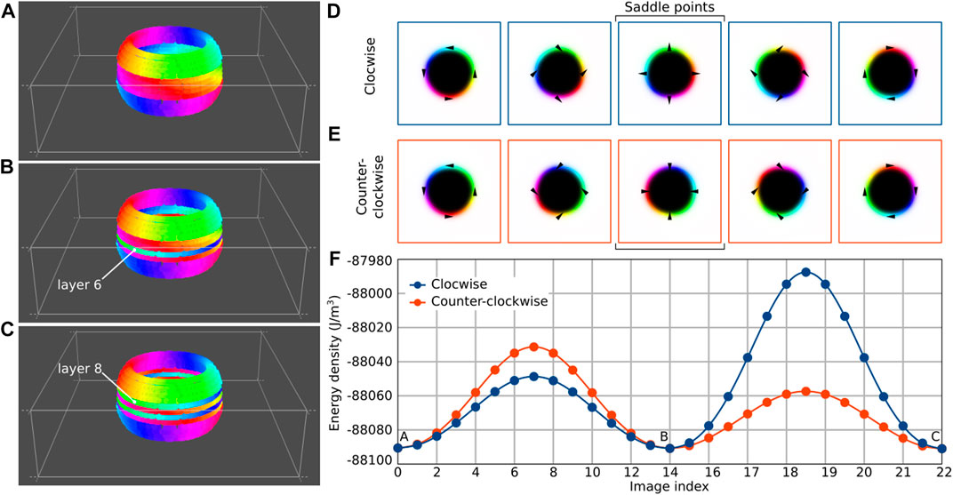
FIGURE 4. (A–C) show the normal bubble, the bubble with one alternating layer and with two alternating layers, respectively. The transitions between those bubbles require a change in the chirality of a certain layer, which can happen clockwise (D) or counterclockwise (E). (F) Contains four minimum energy paths corresponding to transitions (A, B) and (B, C). Saddle points have a Neel bubble shape in all cases.
The chirality switching occurs via an almost homogeneous rotation of the magnetic moments in the domain wall. Such rotation may occur either in clockwise (CW) or counter-clockwise (CCW) directions, see Figures 4D,E. In Figure 4F, we show both MEPs corresponding to CW and CCW rotations. The energy barrier heights are noticeably different for the CW and CCW rotations. However, in both cases, the saddle point on the MEP corresponds to the state with pure Néel-like domain walls where magnetic moments are pointed either inwards or outwards from the center of the bubble, see middle images in Figures 4D,E. The latter explains the different heights of the energy barriers for CW and CCW rotation. Let us consider the switching in the sixth layer, which corresponds to the path between states A and B in the MEP, Figure 4F. When the switching occurs via CW rotation, the magnetization at the saddle point has the same configurations with outwards pointing magnetization, Figure 4D, as in the bottom Néel cap. Let us remind that the outwards or inwards direction of magnetization in Néel caps is defined by the direction of the demagnetizing field near that surface. Thereby, the saddle point for CW rotation coincides with the direction of the demagnetizing field. In the case of CCW rotation, the magnetization at the saddle point, Figure 4E, is pointed against the demagnetizing field, and such configuration has higher energy.
For the same reasons, the switching in the eighth layer, which corresponds to the path between states B and C, has the lower energy in the case of CCW rotation. The eighth layer is close to the top surface of the film, where the magnetization of the Néel cap is pointed inwards, as well as the saddle point for the CCW rotation, Figure 4E.
The difference in energy barriers for the transitions from state A to B and from states B to C can be attributed to the proximity of the switched layer to the surface. The eighth layer is positioned closer to the top surface than the sixth layer to the bottom surface. Consequently, the demagnetizing field, which is most prominent near the surfaces, exerts a more significant influence on the energy of the eighth layer. Therefore, the energy difference between CW and CCW rotations in switching the eighth layer (transition from B to C) is more significant than in switching the sixth layer (transition from A to B).
The optimal MEP, which follows the transitions with the lowest energy berries, in this case, corresponds to the following sequence of transitions. First, the chirality switches in the sixth layer via CW rotation, and then it switches in the eighth layer via CCW rotation. Due to the symmetry of the problem, there is also an equivalent MEP where the CCW switching first occurs in the eighth layer, and then the sixth layer switches via CW rotation.
The magnetic bubbles discussed above can be attributed to the topological states. The topological invariant or topological charge which defines the homotopy class of these solutions can be written as
where integration is carried out in each of the layers. The direction of m far from the bubble center, which represents the base point of the homotopy group, aligns with
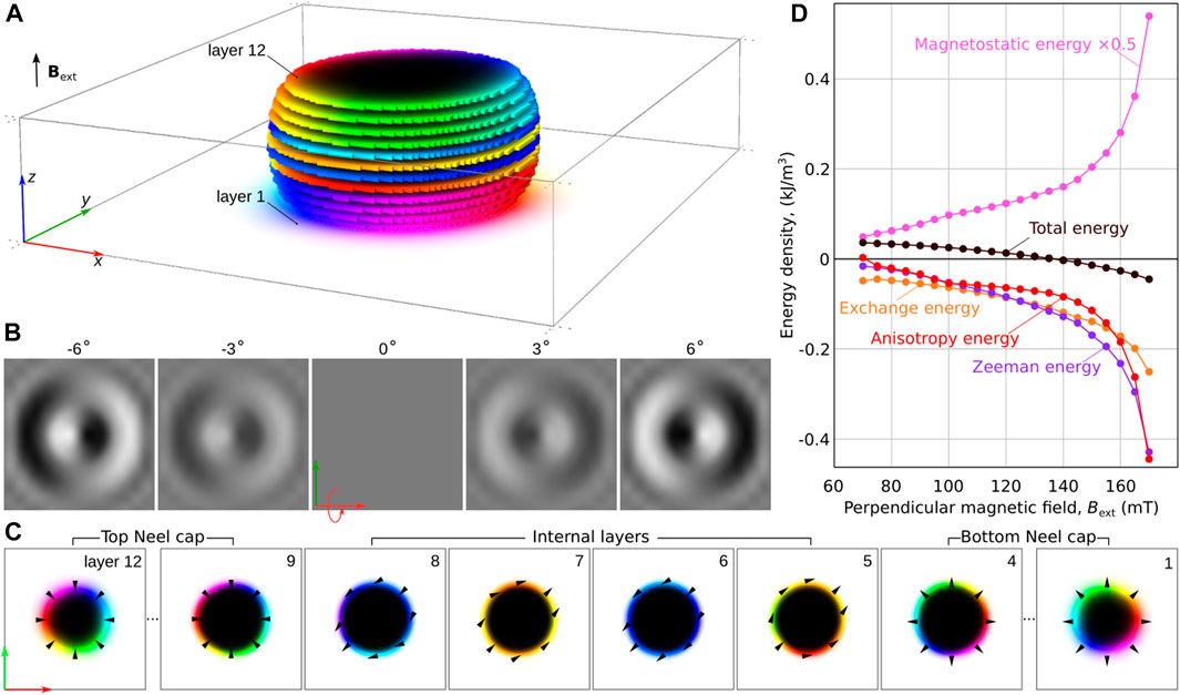
FIGURE 5. The magnetic bubble with zero topological charges in the middle magnetic layers. (A) Magnetic structure of the bubble; (B) Lorenz TEM simulated images at different angles of the incident electron beam; (C) The magnetization distribution in magnetic layers containing the magnetic bubble. (D) Energy variation of a topologically trivial magnetic bubble as a function of the perpendicular magnetic field. The total energy and its distinct components are presented relative to the topological magnetic bubble, as shown in Figure 4A.
Figure 5D shows the energy of magnetic bubbles with a trivial configuration in the internal layers as a function of the external magnetic field. In this case, the energy of this state is calculated relative to the energy of the topological bubble. The term “topological bubble” refers to any magnetic bubble with either fixed or alternating chirality, as their energies are nearly identical in the whole range of their coexistence. Interestingly, at high fields, above 140 mT, the trivial bubble becomes energetically more favorable than the topological bubble. By analyzing the decay of the Zeeman and anisotropy energy terms, which are directly related to the bubble domain size, we can deduce that the trivial bubble gains energy due to its faster reduction in size compared to the topological bubble as the field increases.
In this study, we examined a micromagnetic model of a multilayer system and reported several key findings. First, when interlayer exchange coupling (IEC) and interfacial Dzyaloshinskii-Moriya interaction (iDMI) are absent, we observe a wide diversity of magnetic bubble configurations with distinct domain wall orderings. Specifically, we identified stable solutions for magnetic bubbles exhibiting alternating chirality of the domain wall in adjacent layers. These bubbles share a unique characteristic with bubble-skyrmions in that they are transparent to Lorentz transmission electron microscopy (LTEM) when the electron beam is incident normal to the film surface. The LTEM contrast only becomes visible when the sample is tilted relative to the electron beam.
Furthermore, these configurations can coexist alongside regular magnetic bubbles across a broad range of external magnetic fields. This suggests the potential use of sequential magnetic bubbles with different domain wall types for data encoding. For instance, the magnetic bubbles of alternate chirality and bubbles with fixed chirality can be used as binary data bits of “0” and “1”, respectively. This approach provides an alternative to other methods for data encoding with magnetic solitons [45] that involve chiral bobbers and skyrmion tubes [46], or skyrmions and antiskyrmions [47]. However, the multilayer systems discussed in this work possess distinct advantages over thin films of chiral magnets. For instance, unlike many chiral magnets, these magnetic multilayer systems comprising Co, Fe, and Ni elements typically exhibit significantly higher Curie temperatures that exceed room temperature. This characteristic enhances their practical usability for various applications. Additionally, the fabrication of such multilayers using sputter deposition is a well-established technology widely employed in the industry. On the other hand, the multilayer systems prepared by sputter deposition often exhibit some disorder due to their granular structure [48]; [49]; [50]. Such disorder represents a secondary effect for static properties of magnetic bubbles but should be taken into account when their dynamic properties are studied [51]. The attempts to implement the granular structure in micromagnetic modeling of magnetic multilayer can be found, e.g., in Refs. [52] and [23]. Additionally, our studies raise intriguing new inquiries. For instance, it would be of great interest to develop a reliable approach for controlling the nucleation of bubbles with specific domain wall types. An efficient method to detect these states beyond LTEM is also needed.
We hope our findings will encourage further investigation into exchange-decoupled multilayer systems as a promising platform for spintronic applications.
The original contributions presented in the study are included in the article/Supplementary Material, further inquiries can be directed to the corresponding authors.
AS and NK conceived the project. AS performed micromagnetic calculations. VK performed the minimum energy path calculations. FR provided the required modification of the Excalibur software and participated in the discussions. NK wrote the first draft of the manuscript. All authors contributed to the article and approved the submitted version.
The authors acknowledge financial support from the Icelandic Research Fund (Grant No. 217750), the University of Iceland Research Fund (Grant No. 15673), the Swedish Research Council, and the European Research Council (ERC) under the European Union’s Horizon 2020 research and innovation program (Grant No. 856538, project “3D MAGiC”).
NK acknowledges O. Hellwig, R. Salikhov, and F. Samad for fruitful discussions.
The authors declare that the research was conducted in the absence of any commercial or financial relationships that could be construed as a potential conflict of interest.
All claims expressed in this article are solely those of the authors and do not necessarily represent those of their affiliated organizations, or those of the publisher, the editors and the reviewers. Any product that may be evaluated in this article, or claim that may be made by its manufacturer, is not guaranteed or endorsed by the publisher.
The Supplementary Material for this article can be found online at: https://www.frontiersin.org/articles/10.3389/fphy.2023.1223609/full#supplementary-material
1. Manton N, Sutcliffe P. Topological solitons. In: Cambridge monographs on mathematical Physics. Cambridge University Press (2004). doi:10.1017/CBO9780511617034
2. Dzyaloshinsky I. A thermodynamic theory of “weak” ferromagnetism of antiferromagnetics. J Phys Chem Sol (1958) 4:241–55. doi:10.1016/0022-3697(58)90076-3
3. Moriya T. Anisotropic superexchange interaction and weak ferromagnetism. Phys Rev (1960) 120:91–8. doi:10.1103/PhysRev.120.91
4. Bogdanov AN, Yablonskii DA. Thermodynamically stable “vortices” in magnetically ordered crystals. the mixed state of magnets. Sov Phys JETP (1989) 68.
5. Rybakov FN, Kiselev NS. Chiral magnetic skyrmions with arbitrary topological charge. Phys Rev B (2019) 99:064437. doi:10.1103/PhysRevB.99.064437
6. Foster D, Kind C, Ackerman PJ, Tai J-SB, Dennis MR, Smalyukh II. Two-dimensional skyrmion bags in liquid crystals and ferromagnets. Nat Phys (2019) 15:655–9. doi:10.1038/s41567-019-0476-x
7. Bogolubsky I. Three-dimensional topological solitons in the lattice model of a magnet with competing interactions. Phys Lett A (1988) 126:511–4. doi:10.1016/0375-9601(88)90049-7
8. Sutcliffe P. Skyrmion knots in frustrated magnets. Phys Rev Lett (2017) 118:247203. doi:10.1103/PhysRevLett.118.247203
9. Rybakov FN, Kiselev NS, Borisov AB, Döring L, Melcher C, Blügel S. Magnetic hopfions in solids. APL Mater (2022) 10:111113. doi:10.1063/5.0099942
10. Thiele AA. The theory of cylindrical magnetic domains. Bell Syst Tech J (1969) 48:3287–335. doi:10.1002/j.1538-7305.1969.tb01747.x
11. Malozemoff A, Slonczewski JC. Magnetic domain walls in bubble materials: Advances in materials and device research, vol. 1. Academic Press (1979).
12. Kooy C. Experimental and theoretical study of the domain configuration in thin layers of bafe12o19. Philips Res Repts (1960) 15.
13. Bobeck A. Properties and device applications of magnetic domains in orthoferrites. bell Syst Tech J (1967) 46:1901–25. doi:10.1002/j.1538-7305.1967.tb03177.x
14. Fert A, Reyren N, Cros V. Magnetic skyrmions: Advances in physics and potential applications. Nat Rev Mater (2017) 2:17031–15. doi:10.1038/natrevmats.2017.31
15. Göbel B, Mertig I, Tretiakov OA. Beyond skyrmions: Review and perspectives of alternative magnetic quasiparticles. Phys Rep (2021) 895:1–28. doi:10.1016/j.physrep.2020.10.001
16. Hellwig O, Berger A, Fullerton EE. Domain walls in antiferromagnetically coupled multilayer films. Phys Rev Lett (2003) 91:197203. doi:10.1103/physrevlett.91.197203
17. Davies JE, Hellwig O, Fullerton EE, Denbeaux G, Kortright J, Liu K. Magnetization reversal of co/pt multilayers: Microscopic origin of high-field magnetic irreversibility. Phys Rev B (2004) 70:224434. doi:10.1103/physrevb.70.224434
18. Hellwig O, Berger A, Kortright JB, Fullerton EE. Domain structure and magnetization reversal of antiferromagnetically coupled perpendicular anisotropy films. J Magnetism Magn Mater (2007) 319:13–55. doi:10.1016/j.jmmm.2007.04.035
19. Montoya S, Couture S, Chess J, Lee J, Kent N, Im M-Y, et al. Resonant properties of dipole skyrmions in amorphous fe/gd multilayers. Phys Rev B (2017) 95:224405. doi:10.1103/physrevb.95.224405
20. Chesnel K, Westover AS, Richards C, Newbold B, Healey M, Hindman L, et al. Morphological stripe-bubble transition in remanent magnetic domain patterns of co/pt multilayer films and its dependence on co thickness. Phys Rev B (2018) 98:224404. doi:10.1103/physrevb.98.224404
21. Fallarino L, Oelschlägel A, Arregi J, Bashkatov A, Samad F, Böhm B, et al. Control of domain structure and magnetization reversal in thick co/pt multilayers. Phys Rev B (2019) 99:024431. doi:10.1103/physrevb.99.024431
22. Heigl M, Koraltan S, Vaňatka M, Kraft R, Abert C, Vogler C, et al. Dipolar-stabilized first and second-order antiskyrmions in ferrimagnetic multilayers. Nat Commun (2021) 12:2611. doi:10.1038/s41467-021-22600-7
23. Salikhov R, Samad F, Arekapudi SSPK, Ehrler R, Lindner J, Kiselev NS, et al. Control and tunability of magnetic bubble states in multilayers with strong perpendicular magnetic anisotropy at ambient conditions. Phys Rev B (2022) 106:054404. doi:10.1103/physrevb.106.054404
24. Moreau-Luchaire C, Moutafis C, Reyren N, Sampaio J, Vaz C, Van Horne N, et al. Additive interfacial chiral interaction in multilayers for stabilization of small individual skyrmions at room temperature. Nat nanotechnology (2016) 11:444–8. doi:10.1038/nnano.2015.313
25. Jiang W, Upadhyaya P, Zhang W, Yu G, Jungfleisch MB, Fradin FY, et al. Blowing magnetic skyrmion bubbles. Science (2015) 349:283–6. doi:10.1126/science.aaa1442
26. Pollard SD, Garlow JA, Yu J, Wang Z, Zhu Y, Yang H. Observation of stable néel skyrmions in cobalt/palladium multilayers with lorentz transmission electron microscopy. Nat Commun (2017) 8:14761. doi:10.1038/ncomms14761
27. Zhang S, Zhang J, Wen Y, Chudnovsky EM, Zhang X. Determination of chirality and density control of néel-type skyrmions with in-plane magnetic field. Commun Phys (2018) 1:36. doi:10.1038/s42005-018-0040-5
28. Li M, Lau D, De Graef M, Sokalski V. Lorentz tem investigation of chiral spin textures and néel skyrmions in asymmetric [pt/(co/ni) m/ir] n multi-layer thin films. Phys Rev Mater (2019) 3:064409. doi:10.1103/physrevmaterials.3.064409
29. McCray AR, Cote T, Li Y, Petford-Long AK, Phatak C. Understanding complex magnetic spin textures with simulation-assisted lorentz transmission electron microscopy. Phys Rev Appl (2021) 15:044025. doi:10.1103/physrevapplied.15.044025
30. Denneulin T, Caron J, Müller-Caspary K, Boulle O, Kovács A, Dunin-Borkowski RE. Visibility and apparent size of néel-type magnetic skyrmions in fresnel defocus images of multilayer films. Microsc Microanalysis (2021) 27:1356–65. doi:10.1017/s1431927621012927
31. Hubert A, Schäfer R. Magnetic domains: The analysis of magnetic microstructures. Springer Science & Business Media (2008).
32. Vansteenkiste A, Leliaert J, Dvornik M, Helsen M, Garcia-Sanchez F, Van Waeyenberge B. The design and verification of mumax3. AIP Adv (2014) 4:107133. doi:10.1063/1.4899186
33. Rybakov FN, Babaev E. Excalibur software (2020). URL: http://quantumandclassical.com/excalibur/.
34. Di Fratta G, Muratov CB, Rybakov FN, Slastikov VV. Variational principles of micromagnetics revisited. SIAM J Math Anal (2020) 52:3580–99. doi:10.1137/19M1261365
35. Soumyanarayanan A, Raju M, Gonzalez Oyarce A, Tan AK, Im M-Y, Petrović AP, et al. Tunable room-temperature magnetic skyrmions in ir/fe/co/pt multilayers. Nat Mater (2017) 16:898–904. doi:10.1038/nmat4934
36. Rybakov FN, Pervishko A, Eriksson O, Babaev E. Antichiral ferromagnetism. Phys Rev B (2021) 104:L020406. doi:10.1103/PhysRevB.104.L020406
37. LaBonte A. Two-dimensional bloch-type domain walls in ferromagnetic films. J Appl Phys (1969) 40:2450–8. doi:10.1063/1.1658014
38. Xu S, Dunlop DJ. Micromagnetic modeling of bloch walls with néel caps in magnetite. Geophys Res Lett (1996) 23:2819–22. doi:10.1029/96gl01568
39. Lau Y-C, Chi Z, Taniguchi T, Kawaguchi M, Shibata G, Kawamura N, et al. Giant perpendicular magnetic anisotropy in ir/co/pt multilayers. Phys Rev Mater (2019) 3:104419. doi:10.1103/physrevmaterials.3.104419
40. Salikhov R, Samad F, Schneider S, Pohl D, Rellinghaus B, Böhm B, et al. Multilayer metamaterials with mixed ferromagnetic domain core and antiferromagnetic domain wall structure (2023). arXiv preprint arXiv:2304.14775.
41. Salikhov R, Samad F, Böhm B, Schneider S, Pohl D, Rellinghaus B, et al. Control of stripe-domain-wall magnetization in multilayers featuring perpendicular magnetic anisotropy. Phys Rev Appl (2021) 16:034016. doi:10.1103/physrevapplied.16.034016
42. Omelchenko P, Heinrich B, Girt E. Measurements of interlayer exchange coupling of pt in py|pt|py system. Appl Phys Lett (2018) 113:142401. doi:10.1063/1.5050935
43. Bessarab PF, Uzdin VM, Jónsson H. Potential energy surfaces and rates of spin transitions. Z für Physikalische Chem (2013) 130708000310008. doi:10.1524/zpch.2013.0403
44. Bessarab PF, Uzdin VM, Jónsson H. Harmonic transition-state theory of thermal spin transitions. Phys Rev B (2012) 85:184409. doi:10.1103/PhysRevB.85.184409
45. Fert A, Cros V, Sampaio J. Skyrmions on the track. Nat nanotechnology (2013) 8:152–6. doi:10.1038/nnano.2013.29
46. Zheng F, Rybakov FN, Borisov AB, Song D, Wang S, Li Z-A, et al. Experimental observation of chiral magnetic bobbers in b20-type fege. Nat nanotechnology (2018) 13:451–5. doi:10.1038/s41565-018-0093-3
47. Hoffmann M, Zimmermann B, Müller GP, Schürhoff D, Kiselev NS, Melcher C, et al. Antiskyrmions stabilized at interfaces by anisotropic dzyaloshinskii-moriya interactions. Nat Commun (2017) 8:308. doi:10.1038/s41467-017-00313-0
48. Pierce M, Davies J, Turner J, Chesnel K, Fullerton E, Nam J, et al. Influence of structural disorder on magnetic domain formation in perpendicular anisotropy thin films. Phys Rev B (2013) 87:184428. doi:10.1103/physrevb.87.184428
49. Chen Y, Sun A-C, Lee H, Lu H-C, Wang S-F, Sharma P. Enhanced coercivity of hcp co–pt alloy thin films on a glass substrate at room temperature for patterned media. J Magnetism Magn Mater (2015) 391:12–6. doi:10.1016/j.jmmm.2015.04.080
50. Böhm B, Fallarino L, Pohl D, Rellinghaus B, Nielsch K, Kiselev NS, et al. Antiferromagnetic domain wall control via surface spin flop in fully tunable synthetic antiferromagnets with perpendicular magnetic anisotropy. Phys Rev B (2019) 100:140411. doi:10.1103/physrevb.100.140411
51. Reichhardt C, Reichhardt CJO, Milošević M. Statics and dynamics of skyrmions interacting with disorder and nanostructures. Rev Mod Phys (2022) 94:035005. doi:10.1103/revmodphys.94.035005
Keywords: bubble-skyrmions, bubble domains, multilayer systems, interfacial dzyaloshinskii-moria interaction, interlayer exchange coupling, micromagnetic simulations
Citation: Savchenko AS, Kuchkin VM, Rybakov FN and Kiselev NS (2023) Magnetic bubbles with alternating chirality in domain walls. Front. Phys. 11:1223609. doi: 10.3389/fphy.2023.1223609
Received: 16 May 2023; Accepted: 31 May 2023;
Published: 09 June 2023.
Edited by:
Börge Göbel, Martin Luther University of Halle-Wittenberg, GermanyReviewed by:
Charles Reichhardt, Los Alamos National Laboratory (DOE), United StatesCopyright © 2023 Savchenko, Kuchkin, Rybakov and Kiselev. This is an open-access article distributed under the terms of the Creative Commons Attribution License (CC BY). The use, distribution or reproduction in other forums is permitted, provided the original author(s) and the copyright owner(s) are credited and that the original publication in this journal is cited, in accordance with accepted academic practice. No use, distribution or reproduction is permitted which does not comply with these terms.
*Correspondence: Andrii S. Savchenko, YS5zYXZjaGVua29AZnotanVlbGljaC5kZQ==; Nikolai S. Kiselev, bi5raXNlbGV2QGZ6LWp1ZWxpY2guZGU=
Disclaimer: All claims expressed in this article are solely those of the authors and do not necessarily represent those of their affiliated organizations, or those of the publisher, the editors and the reviewers. Any product that may be evaluated in this article or claim that may be made by its manufacturer is not guaranteed or endorsed by the publisher.
Research integrity at Frontiers
Learn more about the work of our research integrity team to safeguard the quality of each article we publish.