- 1Department Electronic and Communication Engineering, College of Computer Science and Electronic Engineering, Hunan University, Changsha, China
- 2College of Electronic Science, National University of Defense Technology, Changsha, China
The channel matrix of the commonly used uniform circular array-based orbital angular momentum (UCA-OAM) system reaches the full-rank state when the degree of freedom (DoF) is limited only by the number of UCA antenna elements. The rank of the channel matrix of the UCA-OAM system is equal to DoF under this condition. However, the practical DoF of the UCA-OAM system is always affected by other transmission factors, such as the transmission distance and the radius of the receiving antenna. Therefore, by exploiting the practical DoF of the UCA-OAM system affected by the transmission distance and the radii of the receiving antenna and transmission antenna, a novel channel capacity model of the UCA-OAM communication system with a deficient-rank channel (DRC) matrix is first proposed. Moreover, the formulas of the channel matrix and channel capacity for the DRC matrix are analytically derived. The results of numerical simulations indicate that when the practical transmission factors including transmission distance and radii of the receiving antenna and transmission antenna are considered, the UCA-OAM communication system with the DRC matrix has less channel capacity than that with the full-rank channel (FRC) matrix. These simulated results provide helpful guidance on the practical application of the UCA-OAM communication system.
1 Introduction
With the rapid progress in 5G deployment, the focus of wireless research is increasingly shifting to 6G [1]. The goal of 5G systems is to provide a peak data rate of 10 Gbps per user[2], while 6G is expected to increase the capacity by 10–100 times more than 5G [3]. Three key services offered by 6G, truly immersive XR, high-fidelity mobile holograms, and digital twins, bring huge capacity requirements. Therefore, how to meet the massive capacity demand brought by 6G communication applications has become an urgent research direction for 6G202 [40]. Orbital angular momentum (OAM), as a novel mode division multiplexing [4, 5], shows great potential in increasing capacity, so OAM-based wireless communication technology has attracted widespread attention as a candidate technology for 6G.
Angular momentum (AM) is one of the basic physical properties of electromagnetic waves, and the angular momentum of a general near-axis beam can be decomposed into spin angular momentum (SAM) and OAM [6, 7]. OAM is characterized by electromagnetic waves with a spiral phase plane in the direction of propagation. Allen et al. [8] found that Laguerre–Gaussian (LG) beams with a phase distribution of eilφ carry OAM, where φ is the azimuth and l is the OAM mode (l is an unbounded integer), whose absolute value represents the number of phase changes from 0 to 2π in a spiral period. Beams with different OAM modes are orthogonal to each other and can be multiplexed along the same beam axis to transmit multiple coaxial data streams [9-13]. Therefore, this multiplexing technology based on OAM can potentially improve the capacity and spectral efficiency of millimeter wave wireless communication systems [14, 15] first demonstrated experimentally that it is possible to propagate and use the properties of twisted incoherent radio waves to simultaneously transmit to infinity more radio channels with the same frequency band by encoding them in different OAM modes. [16] employed OAM multiplexing technology for terabit free-space data transmission, and the results of the study demonstrated that OAM is a new degree of freedom (DoF) that can increase the capacity of free-space communication. [14] used four independent OAM beams, each polarized by two polarization states, to achieve 32-Gbits−1 mm wave communication with a transmission link of 2.5 m and a spectral efficiency of 16 bits−1Hz−1. The combination of OAM multiplexing and traditional spatial multiplexing is used to achieve a 16-Gbits−1 mm wave link with a transmission distance of 1.8 m [17].
Next, we focus on wireless communication with a uniform circular array-based OAM (UCA-OAM) system. The antenna elements in UCAs are provided with the same input signal, but there is a continuous phase delay from the antenna unit to the antenna element, such that the phase increases by an integer multiple of 2π after a full circle. By associating an 8 × 8 UCA to 8 × 8 Butler matrix, one can generate waves carrying eight different OAM modes simultaneously and independently and, thus, multiplex signals at the same frequency and polarization [18]. Since radio waves with OAM characteristics have been generated using antenna arrays consisting of concentric UCAs [4, 5], UCA-OAM systems have become increasingly widely used. The spatial transmission characteristics of OAM beams in OAM-multiplexed transmission systems and the channel capacity under different receiving array configurations are analyzed, and the simulation results show that as the transmission distance and OAM module order increase, the divergence of the OAM beam becomes larger [19]. When the physical layer security theory is applied to the multi-mode OAM system based on UCA, the system using the vortex wave is superior to the conventional communication system using the plane electromagnetic wave in terms of safety [20, 21] demonstrated that OAM-based multiple-input–multiple-output (OAM-MIMO) multiplexing systems using multiple UCAs successfully achieved 120 Gbps wireless data transmission over a distance of 10 m in the 28 GHz band. Both OAM and MIMO provide physical freedom for multiplexing, and the two physical resources are independent of each other. Hence, the spectral efficiency can be further improved by combining OAM and MIMO [20, 21]. To further improve spectral efficiency, non-orthogonal multiple access (NOMA) has recently been introduced in OAM-MIMO systems [22-24].
Nevertheless, the aforementioned studies are based on the assumption that each channel matrix is full rank, but in practical MIMO scenarios, the channel matrix is not full rank because of the poor scattering environment for channel capture [25, 26]. In addition, for OAM-based communications, the channel matrix cannot reach full rank due to propagation divergence of the OAM-carrying beams [27]. As we all know, the rank of a channel matrix plays an important role in the evaluation of UCA-OAM systems. However, when the UCA-OAM communication systems are limited by the actual transmission conditions, the rank of the channel matrix is less than the number of Tx (Rx) UCA antennas, i.e., deficient-rank channel (DRC) matrix. By far, the channel capacity analysis of the UCA-OAM system based on the DRC matrix is an unexplored area of research, as this topic is much more complicated and limited by the actual transmission conditions.
Motivated by the aforementioned facts, we strive to study the UCA-OAM system with the DRC matrix in order to analyze its actual performances. Our goal is to obtain the capacity performance of UCA-OAM systems with the DRC matrix considering the actual transmission conditions. To this end, we use Laguerre–Gaussian beams to represent the OAM beams, as vector antenna arrays can generate radio beams, which exhibit spin and orbital angular momentum characteristics similar to those of helical LG beams in paraxial optics [4].
In this paper, we propose a UCA-OAM system with the DRC matrix. The performance of the UCA-OAM system with the DRC matrix is analyzed by calculating the capacity. Specifically, the contributions of this paper are summarized as follows.
1) We propose the practical DoF which is affected by transmission distance and the radii of the receiving antenna and transmission antenna.
2) When the practical DoF of the UCA-OAM system affected by practical transmission factors is considered, we establish the relationship between the practical DoF and the rank of the DRC matrix, and the formulas of the DRC matrix and capacity for the DRC matrix are analytically derived. In addition, the capacity of the UCA-OAM system with the DRC matrix is simulated for performance evaluation.
3) Compared with the ideal UCA-OAM system with the full-rank channel (FRC) matrix, the transmission distance and frequency factors have a deeper impact on the proposed UCA-OAM system with the DRC matrix. The results of numerical simulations indicate that when the practical transmission factors including transmission distance and the radii of the receiving antenna and transmission antenna are considered, the UCA-OAM communication system with the DRC matrix has less capacity than that of the UCA-OAM communication system with the FRC matrix.
The remainder of this paper is organized as follows: the system model and principle of the UCA-OAM system with the DRC matrix are introduced in Section 2. The simulation results are given in Section 3. Finally, the conclusion is given in Section 4.
2 System model
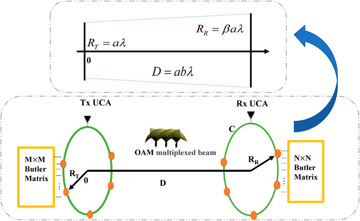
In this paper, we consider a UCA-OAM system using the Butler matrix. Figure 1 shows the UCA-OAM system, where the transmitter end and the receiver end have a UCA with the M × M Butler matrix and a UCA with the N × N Butler matrix, respectively. For the convenience of calculation, in this paper, we assume M = N. The system can simultaneously and independently generate electromagnetic waves with M different OAM modes with the same frequency [18]. As can be seen from Figure 1, the transmission (Tx) UCA has M equidistant antenna elements, and the reception (Rx) UCA has N equidistant antenna elements around the beam axis. The radii of Tx UCA and Rx UCA are RT = aλ and RR = βaλ, respectively. The propagating distance is D = baλ, where β and b represent the scale of Rx aperture and link distance compared with the Tx aperture, respectively. λ is the wavelength. Here, it is noteworthy that the center of Tx UCA is aligned with that of Rx UCA, and D is large enough to make the Fresnel approximation effective.
2.1 Multiplexing/demultiplexing of information-carrying OAM beams
The OAM beams can be generated by attaching the incremental phases to M equidistant antennas of Tx UCA. The phase shifts
where αt is the combination of all constants relative to each Tx antenna element, j is the constant current density vector, i is the imaginary unit, k is the wave vector,
When signal S(t) is transmitted, the information-carrying OAM beam US(r, φ, t) can be described as [16]
Generally, at the receiver end, the phase distribution of exp (−ilφ) is used to demodulate the information-carrying OAM beam US(r, φ, t), and the original signal S(t) can be obtained.
Based on Eq. 2, the multiplexing of information-carrying OAM beams with M OAM modes is expressed as
where
where (.)n represents the field component detected by the nth (n = 1,2,. ., N) RX antenna element. Notably, choosing a different value of the OAM mode l′, the desired original signal from the OAM multiplexing beams UMUX (r, φ, t) can be obtained, and this is the OAM demultiplexing [16].
2.2 The practical DoF of a UCA-OAM system
To study the performance of a UCA-OAM system with the DRC matrix, we need to use the concept of DoF of an OAM wireless communication channel. In OAM wireless communications, DoF can be defined as the total number of OAM modes that can be transmitted on a wireless channel to carry the information signals [32]. OAM multiplexing has long been conceived to support infinite DoFs and an infinite channel capacity for free-space line-of-sight communication in radio frequency (RF) channels [32]. However, in the practical OAM system, DoF is usually limited by the transmitter size, receiver size, and propagation distance [27, 32, 33]. Compared with conventional antenna arrays, the number of UCA antenna elements has an additional impact on transmitted OAM modes: it determines the maximum OAM modes that can be generated by UCA [4]. In the limitation of the number of Tx UCA antenna elements, the transmitted OAM modal set A is expressed as [4, 34]
where
The vector antenna arrays can generate radio beams which exhibit spin and orbital angular momentum characteristics similar to those of helical LG beams in paraxial optics [4]. Moreover, LG modes are the most common and proven well-defined OAM modes [32]. Based on this, we choose to use the LG mode to describe the OAM mode generated by UCA.
The practical DoF of UCA-OAM systems under the limits of transmitter size, receiver size, and propagation distance is defined as [27, 32, 33]
where
The beam size of any LG mode is described as [37]
where
Based on the definition in Eq. 6, the index pairs lp satisfy the following two rules:
One denotes
By calculating the number of index pairs of lp following
Based on Eq. 12, the practical DoF of the UCA-OAM system under the limits of transmitter size, receiver size, and propagation distance, i.e., NOAM, is obtained. Obviously, the value of DoF depends on the size of Tx/Rx UCA and the distance between the two. However, the geometric relationship between the two UCAs, as well as the frequency, also plays an important role.
When we consider not only the limits of the number of UCA antenna elements but also the limits of transmission distance, transmitter size, and receiver size, the practical DoF of the UCA-OAM system is denoted as Q, the transmitted OAM modal set is denoted as U, and the expressions of Q and U are given as
where Q ≤ M.
2.3 Channel model
The receive signal of UCA-OAM systems is expressed as
where
The distance between the mth antenna element of Tx UCA and the nth antenna element of Rx UCA can be expressed as [38]
where ϕn represents the azimuthal angle of Rx UCA corresponding to the nth antenna, and the expression is given as
According to
We define hn;l as the channel gain for the lth OAM mode corresponding to Tx UCA and the nth antenna element at Rx UCA. By superimposing the signals of all antenna elements at Tx UCA, the expression of hn;l is given as
where α is the combination of attenuation and phase rotation error caused by transmitter and receiver modes. Exploiting Bessel function expressions for simplification, we can approximate hn;l as follows:
where
We define channel gain without phase factors as hl, and hl can be expressed as
2.3.1 The full-rank channel matrix
When we only consider the UCA-OAM system with the FRC matrix, the transmitted OAM modal set is
2.3.2 The deficient-rank channel matrix
When we consider the UCA-OAM system with the DRC matrix, the transmitted OAM modal set is
where
2.4 Channel capacity
In this section, the corresponding capacity derivation is developed according to Shannon’s continuous channel capacity formula.
The signal S(t) related to the OAM mode l is transmitted by Tx UCA. When we consider the UCA-OAM system with the FRC matrix, the signal yF,n is received by the nth antenna element of Rx UCA. When we consider the UCA-OAM system with the DRC matrix, the signal yDF,n is received by the nth antenna element of Rx UCA. These expressions are, respectively, given as
where zn is the additive Gaussian white noise with zero mean and variances σ2.
The ultimate channel capacity of the UCA-OAM system with the FRC matrix and that with the DRC matrix are, respectively, expressed as
where λF,l represent the eigenvalues of the channel matrices HF. P represents the transmit power of Tx UCA, and λDF,l represent the eigenvalues of the channel matrices HDF.
3 Simulation results
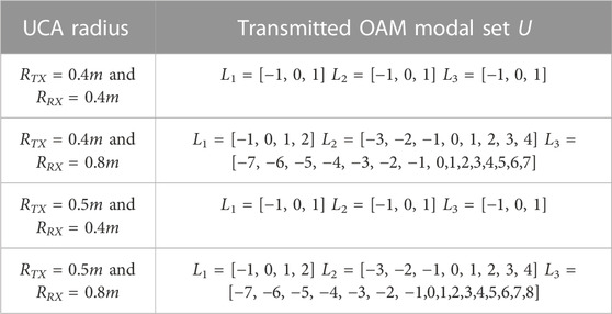
This section evaluates the channel capacity performance of the UCA-OAM system with the DRC matrix. The default simulation parameters are configured as follows: the transmission frequency is 28 GHz, and the transmission distance between the transmitter and receiver is D = 10 m [39]. For the ease of exposition, different OAM modes have the same total transmit SNR, i.e., SNR = 40 dB. In our simulations, α = 121 (except for Figure 6). When M = N = 4, the transmitted OAM modal set U is defined as L1; when M = N = 8, the transmitted OAM modal set U is defined as L2; and when M = N = 16, the transmitted OAM modal set U is defined as L3. Table 1 shows the transmitted OAM modal set U with different UCA radii at a transmission frequency of 28 GHz and a transmission distance of 10 m, which are selected to meet the practical DoF of the UCA-OAM system according to Eq. 6.
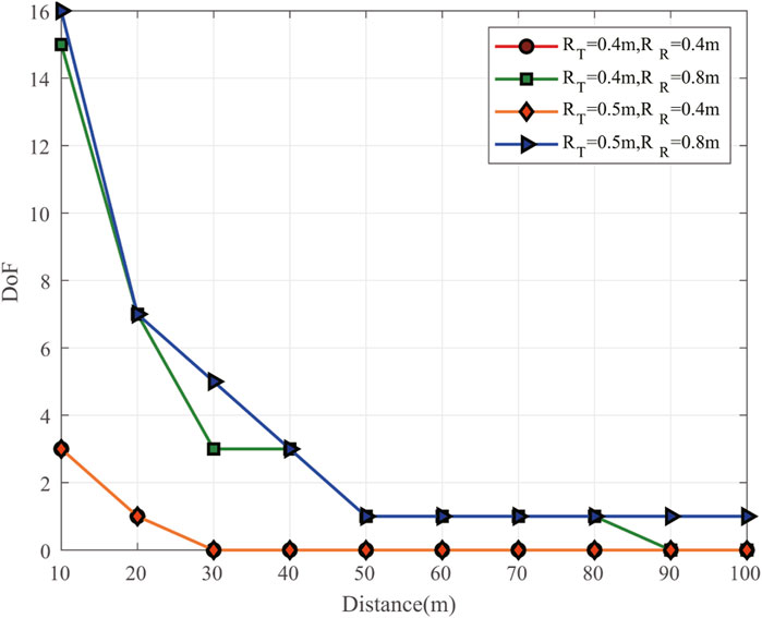
Figure 2 shows the DoF of UCA-OAM systems with respect to the transmission distance for different transmitter and receiver sizes. As shown in Figure 2, we can observe that the DoF value of the UCA-OAM system decreases with the increase in the transmission distance. In addition, we can observe that the DoF value of the UCA-OAM system is highest when the transmission distance is 10 m and the transmitter and receiver sizes are 0.5 m and 0.8 m, respectively. Moreover, we also observe that the OAM-DoF value with RTX = 0.4 m and RRX = 0.4 m is the same as the OAM-DoF value with RTX = 0.5 m and RRX = 0.4 m.
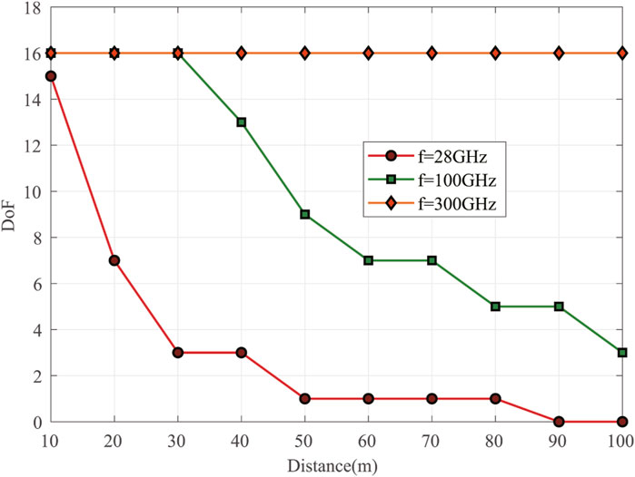
Figure 3 shows the DoF of UCA-OAM systems with respect to the transmission distance for different transmission frequencies (transmitter and receiver sizes are RTX = 0.4 m and RRX = 0.8 m, respectively). As shown in Figure 3, we can observe that the DoF value of the UCA-OAM system decreases with the increase in the transmission distance (except for f = 300 GHz). In addition, we can observe that with an identical distance, the DoF value of f = 28 GHz is lowest when the transmission distance increases. For example, when the transmission distance is 40 m, the DoF value of f = 28 GHz is 3, the DoF value of f = 100 GHz is 13, and the DoF value of f = 300 GHz is 16. It is confirmed that the frequency plays an important role in practical DoF. Moreover, we also observe that the DoF value of f = 300 GHz is fixed when the transmission distance is in the range of 10–100 m.
Figure 4 shows the capacities of the UCA-OAM system with respect to the transmission SNR when considering the DRC matrix (case 1) and FRC matrix (case 2). It can be seen from Figure 4 that the capacity of UCA-OAM systems increases with the increase in the transmission SNR. Figure 4A depicts the capacities of UCA-OAM systems with the DRC matrix and FRC matrix when the waterfilling power allocation is employed. As shown in Figure 4A, the UCA-OAM system with 16 (M = 8, 4) transmission antennas and considering the FRC matrix always has higher capacity than the UCA-OAM system with 16 transmission antennas and considering the DRC matrix. Taking SNR = 40 dB as an example, the capacity of the UCA-OAM system with 16 transmission antennas and considering the FRC matrix s is 12.4487 bits/s/Hz, while the capacity of the UCA-OAM system with 16 transmission antennas and considering the DRC matrix is 3.95647 bits/s/Hz. Figure 4B shows the capacities of UCA-OAM systems considering the DRC matrix and FRC matrix when the equal power allocation is employed. Moreover, compared with Figures 4A, B, we find that with an identical SNR, the UCA-OAM system using waterfilling power allocation has higher capacity than that using equal power allocation. For example, when SNR = 40 dB, the capacity of the UCA-OAM system with 16 transmission antennas and using waterfilling power allocation is 12.4487 bits/s/Hz, while the capacity of the UCA-OAM system with 16 transmission antennas and using equal power allocation is 9.15399 bits/s/Hz.
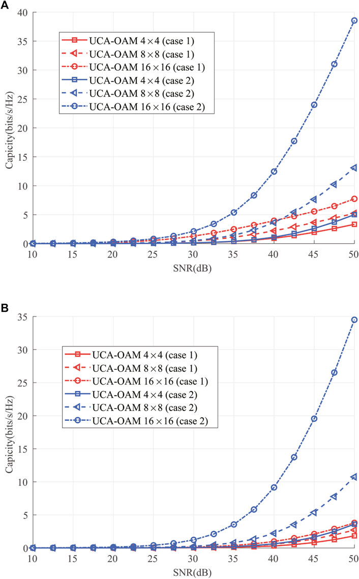
FIGURE 4. Channel capacity versus SNR considering the DRC matrix (case 1) and FRC matrix (case 2). (A) Waterfilling power allocation. (B) Equal power allocation.
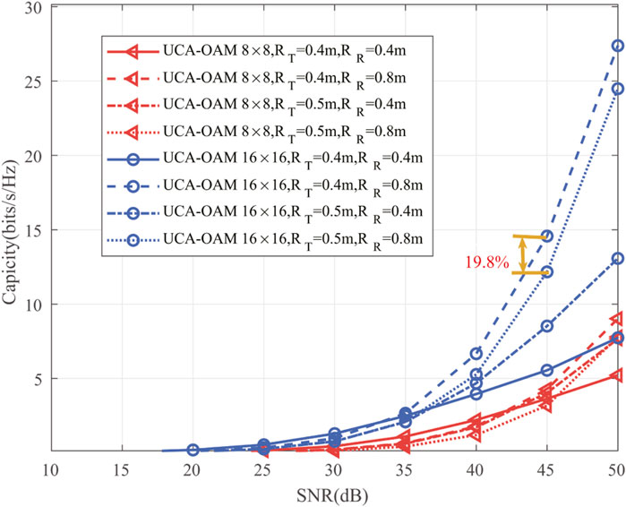
Figure 5 illustrates the impact of the radii of the receiving antenna and transmission antenna on the channel capacity performance considering the DRC matrix. It can be seen from Figure 5 that the capacity of UCA-OAM systems increases with the increase in the transmission SNR. As expected, the UCA-OAM system with 16 transmission antennas has higher capacity than that with eight transmission antennas when the transmission SNR and the radii of the receiving antenna and transmission antenna are fixed. In addition, the radii of the receiving antenna and transmission antenna have a critical impact on the channel capacity performance considering the DRC matrix. We can observe that at low to medium transmission SNR, low radii of the receiving antenna and transmission antenna result in a better channel capacity performance than higher radii of the receiving antenna and transmission antenna. For example, when SNR = 35 dB and M = N = 16, the capacity of RTX = 0.4 m and RRX = 0.4 m is 2.66 bits/s/Hz, while the capacity of RTX = 0.5 m and RRX = 0.4 m is 2.10 bits/s/Hz. Moreover, we can also observe that at high transmission SNR = 45 dB and M = N = 16, the capacity of RTX = 0.4 m and RRX = 0.8 m is 14.5751 bits/s/Hz, while the capacity of RTX = 0.5 m and RRX = 0.8 m is 12.17 bits/s/Hz. This means that one can seek to transmit and receive UCA radii parameters that achieve the highest possible channel capacity performance given a set of constraints.
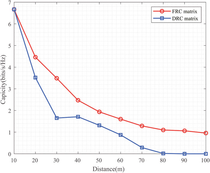
Figure 6 shows the impact of the transmission distance on the channel capacity performance with RTX = 0.4 m, RRX = 0.8 m, and M = N = 16. As shown in Figure 6, when the transmission distance is lower than 30 m and higher than 50 m, the channel capacity of UCA-OAM systems with the DRC matrix decreases with the increase in the distance. Moreover, we find that when the transmission distance is equal to 40 m, the channel capacity of UCA-OAM systems with the DRC matrix is 1.7108 bits/s/Hz, while when the transmission distance is equal to 30 m, the channel capacity of UCA-OAM systems with the DRC matrix is 1.6516 bits/s/Hz. This occurs because when the transmission distance is 40 m and the total transmission SNR is fixed, the number of OAM modes transmitted decreases, and the average power allocated amongst different OAM modes increases. In addition, the channel capacity performance of UCA-OAM systems with the FRC matrix decreases when the transmission distance increases. Comparing the channel capacity of UCA-OAM systems with the DRC matrix with that with the FRC matrix, we can conclude that the practical UCA-OAM system, which is usually limited by the size of transmitter, receiver, and propagation distances, is different from the ideal UCA-OAM system which only considers the influence of the number of UCA array elements in channel capacity performance.
Figure 7 shows the impact of the transmission SNR on the channel capacity performance with RTX = 0.4m, RRX = 0.4 m, and M = N = 16 for different frequencies. The transmitted OAM modal set L3 for different frequencies is shown in Table 2, which are selected to meet the practical DoF of the UCA-OAM system according to Eq. 6. Figure 7A illustrates the channel capacity performance of UCA-OAM systems with the DRC matrix with respect to the transmission SNR. As expected, the channel capacity performance of the UCA-OAM systems with the DRC matrix increases with the increase in the transmission SNR when the transmission frequency is fixed. In addition, when the transmission SNR is lower than 42.5 dB and transmission frequency is fixed, the channel capacity performance of the UCA-OAM systems with the DRC matrix decreases with the increase in the transmission frequency. However, when the transmission SNR is larger than or equal to 42.5 dB, the UCA-OAM system with the transmission frequency f = 100 GHz achieves the highest capacity compared with the UCA-OAM system with the transmission frequency f = 28 GHz and the UCA-OAM system with the transmission frequency f = 300 GHz. The channel capacity performance of the UCA-OAM systems with the FRC matrix with respect to the transmission SNR for different transmission frequencies is depicted in Figure 7B. The trend in Figure 7B can be intuitively explained that the channel capacity performance of the UCA-OAM systems with the FRC matrix is increased when the transmission SNR increases. Moreover, the channel capacity performance of the UCA-OAM systems with the FRC matrix increases with the decrease in the transmission frequency when the transmission SNR is fixed. Comparing Figure 7A with Figure 7B, we can conclude that the frequency factor has a deeper impact on the capacity performance of UCA-OAM systems with the DRC matrix than on the capacity performance of UCA-OAM systems with the FRC matrix.
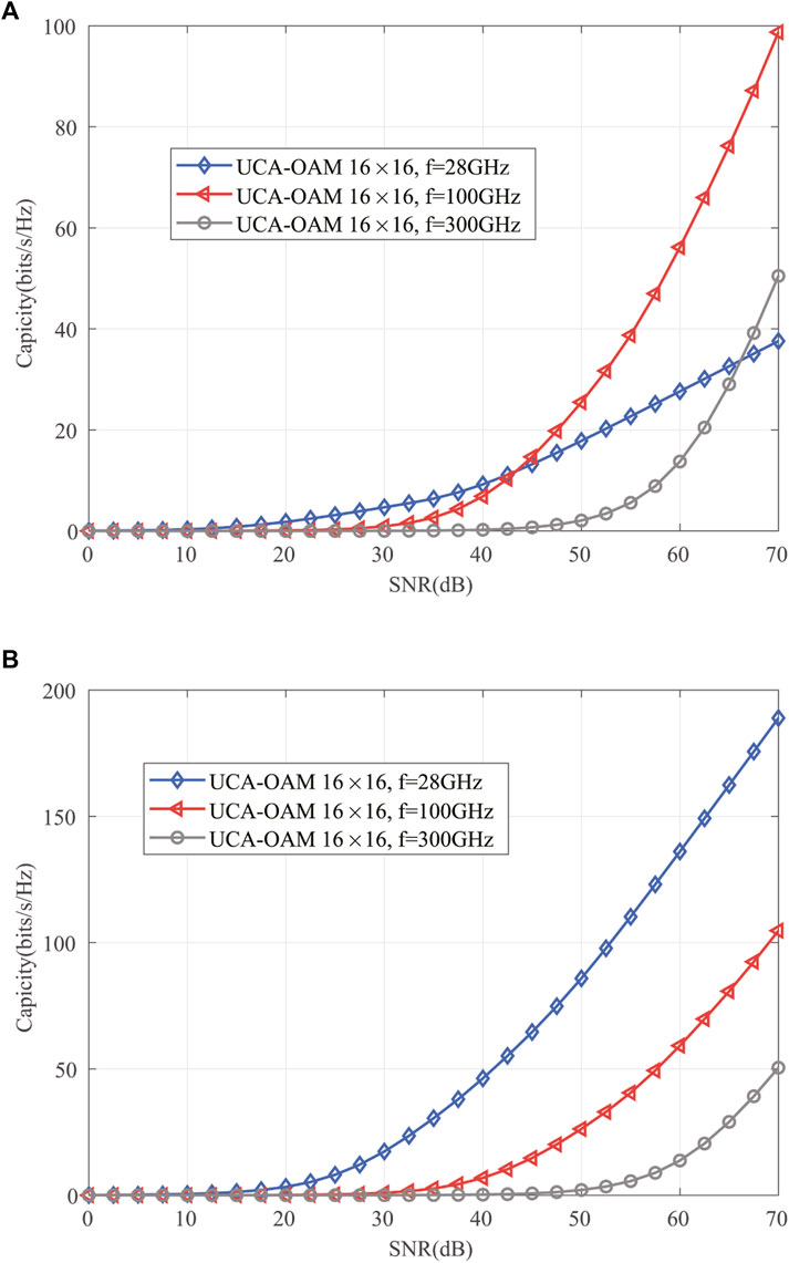
FIGURE 7. Channel capacity versus SNR for different frequencies. (A) UCA-OAM system with the DRC matrix. (B) UCA-OAM system with the FRC matrix.
4 Conclusion
Exploiting the practical DoF of the UCA-OAM system affected by transmission distance and the radii of the receiving antenna and transmission antenna, a novel capacity of UCA-OAM systems with the DRC matrix is first proposed in this paper. For simplicity, we focus on the DoF of the OAM beams represented by an LG beam based on the order of the Laguerre polynomial p = 0. Moreover, we derive the closed forms of the DRC matrix and capacity for the DRC matrix. The results of numerical simulations indicate that the practical UCA-OAM systems with the DRC matrix are different from the ideal UCA-OAM systems with the FRC matrix in capacity performance. Compared with the UCA-OAM systems with the FRC matrix, the transmission distance factor has a deeper impact on the practical UCA-OAM systems with the DRC matrix. Moreover, when the practical transmission factors including transmission distance and the radii of the receiving antenna and transmission antenna are considered, the UCA-OAM communication system with the DRC matrix has less capacity than that with the FRC matrix. The analytical results demonstrate that it is suitable for mass production and supports point-to-point LOS communication scenarios such as mobile backhaul and intra-data center interconnection. The proposed methodology of calculating the DoF and channel capacity of the OAM wireless communication link is limited not only by the divergence of the beam and physical sizes of the transmitter and receiver but also by the atmospheric turbulence. In addition, it is a challenge to perfectly align the transmission and receiving antenna arrays in the implementation of the UCA-OAM systems with the DRC matrix. In the future work, the atmospheric turbulence and antenna array misalignment factors are still needed to be further investigated for the UCA-OAM systems with the DRC matrix.
Data availability statement
The original contributions presented in the study are included in the article/Supplementary Material; further inquiries can be directed to the corresponding authors.
Author contributions
Formal analysis: XY, QM, LT, and ZL; investigation: XY, QM, and ZL; original manuscript preparation: QM, LT, and XY; all authors contributed to the article and approved the submitted version.
Conflict of interest
The authors declare that the research was conducted in the absence of any commercial or financial relationships that could be construed as a potential conflict of interest.
Publisher’s note
All claims expressed in this article are solely those of the authors and do not necessarily represent those of their affiliated organizations, or those of the publisher, the editors, and the reviewers. Any product that may be evaluated in this article, or claim that may be made by its manufacturer, is not guaranteed or endorsed by the publisher.
References
1. Chowdhury MZ, Shahjalal M, Ahmed S, Jang YM. 6g wireless communication systems: applications, requirements, technologies, challenges, and research directions. IEEE Open J Commun Soc (2020) 1:957–75. doi:10.1109/OJCOMS.2020.3010270
2. Karjalainen J, Nekovee M, Benn H, Kim W, Park J, Sungsoo H. Challenges and opportunities of mm-wave communication in 5g networks. In: 2014 9th International Conference on Cognitive Radio Oriented Wireless Networks and Communications (CROWNCOM); 2nd–4th Jun 2014; Oulu, Finland (2014). p. 372–6. doi:10.4108/icst.crowncom.2014.255604
3. Yza B, Ling L, Lu W, Ning H, Xca B, Jie W, et al. Service-aware 6g: an intelligent and open network based on the convergence of communication, computing and caching - sciencedirect. Digital Commun Networks (2020) 6:253–60. doi:10.1016/j.dcan.2020.05.003
4. Thidé B, Then H, Sj?Holm J, Palmer K, Bergman J, Carozzi TD, et al. Utilization of photon orbital angular momentum in the low-frequency radio domain. Phys Rev Lett (2007) 99:087701. doi:10.1103/physrevlett.99.087701
5. Mohammadi SM, Daldorff LKS, Bergman JES, Karlsson RL, Thide B, Forozesh K, et al. Orbital angular momentum in radio—a system study. IEEE Trans Antennas Propagation (2010) 58:565–72. doi:10.1109/TAP.2009.2037701
7. Cohen-Tannoudji C, Dupont-Roc J, Grynberg G. Photons and atoms-introduction to quantum electrodynamics. Weinheim, Germany: WILEY-VCH Verlag (1997).
8. Allen L, Beijersbergen MW, Spreeuw R, Woerdman J. Orbital angular momentum of light and the transformation of laguerre-Gaussian laser modes. Phys Rev A (1992) 45:8185–9. doi:10.1103/physreva.45.8185
9. Gibson G, Courtial J, Padgett MJ, Vasnetsov M, Pas’ko V, Barnett SM, et al. Free-space information transfer using light beams carrying orbital angular momentum. Opt express (2004) 12:5448–56. doi:10.1364/opex.12.005448
10. Yao AM, Padgett MJ. Orbital angular momentum: origins, behavior and applications. Adv Opt Photon (2011) 3:161–204. doi:10.1364/aop.3.000161
11. Molina-Terriza G, Torres JP, Torner L. Twisted photons. Nat Phys (2007) 3:305–10. doi:10.1038/nphys607
12. Cagliero A, Gaffoglio R. On the spectral efficiency limits of an oam-based multiplexing scheme. IEEE Antennas Wireless Propagation Lett (2017) 16:900–3. doi:10.1109/LAWP.2016.2614338
13. Zhang W, Zheng S, Hui X, Dong R, Jin X, Chi H, et al. Mode division multiplexing communication using microwave orbital angular momentum: an experimental study. IEEE Trans Wireless Commun (2017) 16:1308–18. doi:10.1109/TWC.2016.2645199
14. Yan Y, Xie G, Lavery MP, Huang H, Ahmed N, Bao C, et al. High-capacity millimetre-wave communications with orbital angular momentum multiplexing. Nat Commun (2014) 5:4876–9. doi:10.1038/ncomms5876
15. Tamburini F, Mari E, Sponselli A, Thidé B, Bianchini A, Romanato F. Encoding many channels on the same frequency through radio vorticity: first experimental test. New J Phys (2012) 14:033001. doi:10.1088/1367-2630/14/3/033001
16. Wang J, Yang J-Y, Fazal IM, Ahmed N, Yan Y, Huang H, et al. Terabit free-space data transmission employing orbital angular momentum multiplexing. Nat Photon (2012) 6:488–96. doi:10.1038/nphoton.2012.138
17. Ren Y, Li L, Xie G, Yan Y, Cao Y, Huang H, et al. Line-of-sight millimeter-wave communications using orbital angular momentum multiplexing combined with conventional spatial multiplexing. IEEE Trans Wireless Commun (2017) 16:3151–61. doi:10.1109/TWC.2017.2675885
18. Palacin B, Sharshavina K, Nguyen K, Capet N. An 8×8 butler matrix for generation of waves carrying orbital angular momentum (oam). In: 2014 8th European Conference on Antennas and Propagation (EuCAP); 6-11 April 2014; The Hague, Netherlands (2014).
19. Dong J, Wang H, Liu G, Wang Q, Jin J, Li N, et al. Capacity analysis of orbital angular momentum multiplexing transmission system. In: 2020 IEEE International Conference on Communications Workshops (ICC Workshops); Held 7-11 June 2020; Dublin, Ireland (2020). doi:10.1109/ICCWorkshops49005.2020.9145318
20. Zhou C, Liao X, Wang Y, Liao S, Zhou J, Zhang J. Capacity and security analysis of multi-mode orbital angular momentum communications. IEEE Access (2020) 8:150955–63. doi:10.1109/ACCESS.2020.3010957
21. Sasaki H, Lee D, Fukumoto H, Yagi Y, Kaho T, Shiba H, et al. Experiment on over-100-gbps wireless transmission with oam-mimo multiplexing system in 28-ghz band. In: 2018 IEEE Global Communications Conference (GLOBECOM) (IEEE); 9-13 December 2018; Abu Dhabi, UAE (2018).
22. Amin AA, Shin SY. Channel capacity analysis of non-orthogonal multiple access with oam-mimo system. IEEE Wireless Commun Lett (2020) 9:1481–5. doi:10.1109/LWC.2020.2994355
23. Jian M, Chen Y, Yu G. Improving multiple-user capacity through downlink noma in oam systems. In: 2021 IEEE International Conference on Communications Workshops (ICC Workshops); June 14-23, 2021; Montreal, QC, Canada (2021). doi:10.1109/ICCWorkshops50388.2021.9473665
24. Amin AA, Shin SY. Capacity analysis of cooperative noma-oam-mimo based full-duplex relaying for 6g. IEEE Wireless Commun Lett (2021) 10:1395–9. doi:10.1109/LWC.2021.3068654
25. Chae SH, Lee K. Cooperative communication for the rank-deficient mimo interference channel with a reconfigurable intelligent surface. IEEE Trans Wireless Commun (2023) 22:2099–112. doi:10.1109/TWC.2022.3208881
26. Chae SH, Suh C, Chung S-Y. Degrees of freedom of the rank-deficient interference channel with feedback. IEEE Trans Inf Theor (2015) 61:3326–38. doi:10.1109/TIT.2015.2428233
27. Xu J. Degrees of freedom of oam-based line-of-sight radio systems. IEEE Trans Antennas Propagation (2017) 65:1996–2008. doi:10.1109/tap.2017.2671430
28. Chen R, Yao R, Long W-X, Moretti M, Li J. Uca-based oam non-orthogonal multi-mode multiplexing. IEEE Open J Antennas Propagation (2021) 2:181–90. doi:10.1109/OJAP.2021.3051474
29. Courtial J, Robertson DA, Dholakia K, Allen L, Padgett MJ. Rotational frequency shift of a light beam. Phys Rev Lett (1998) 81:4828–30. doi:10.1103/physrevlett.81.4828
30. Yuan Y, Zhang Z, Cang J, Wu H, Zhong C. Capacity analysis of uca-based oam multiplexing communication system. In: 2015 International Conference on Wireless Communications Signal Processing (WCSP); October 15-17, 2015; Jiangsu, China (2015). doi:10.1109/WCSP.2015.7341308
31. Wu H, Yuan Y, Zhang Z, Cang J. Uca-based orbital angular momentum radio beam generation and reception under different array configurations. In: 2014 Sixth International Conference on Wireless Communications and Signal Processing (WCSP); 23-25 October 2014; Hefei, China (2014). doi:10.1109/WCSP.2014.6992134
32. Sawant A, Lee I, Jung BC, Choi E. Ultimate capacity analysis of orbital angular momentum channels. IEEE Wireless Commun (2020) 28:90–6. doi:10.1109/mwc.001.2000258
33. Xu J. Degrees of freedom of oam-based communication systems. In: 2017 IEEE International Symposium on Antennas and Propagation USNC/URSI National Radio Science Meeting; 9-14 July 2017; San Diego (2017). p. 1157–8. doi:10.1109/APUSNCURSINRSM.2017.8072621
34. Liu H, Cheng Y, Qin Y-L, Liu K, Yuan T. Study on the superposition state for the generation of orbital-angular-momentum-carrying beam. In: 2016 Progress in Electromagnetic Research Symposium (PIERS) (IEEE); August 8-11, 2016; Shanghai, China (2016). p. 1252–6.
35. Jing H, Cheng W, Xia X-G, Zhang H. Orbital-angular-momentum versus mimo: orthogonality, degree of freedom, and capacity. In: 2018 IEEE 29th Annual International Symposium on Personal, Indoor and Mobile Radio Communications (PIMRC); September 9-12, 2018; Bologna, Italy (2018). doi:10.1109/PIMRC.2018.8580836
36. Xu J. Generation of laguerre–Gaussian modes by aperture or array sources. IEEE Trans Antennas Propagation (2019) 67:415–29. doi:10.1109/TAP.2018.2874714
37. Phillips RL, Andrews LC. Spot size and divergence for laguerre Gaussian beams of any order. Appl Opt (1983) 22:643–4. doi:10.1364/ao.22.000643
38. Chen R, Xu H, Moretti M, Li J. Beam steering for the misalignment in uca-based oam communication systems. IEEE Wireless Commun Lett (2018) 7:582–5. doi:10.1109/LWC.2018.2797931
39. Yagi Y, Sasaki H, Yamada T, Lee D. 200 gb/s wireless transmission using dual-polarized oam-mimo multiplexing with uniform circular array on 28 ghz band. IEEE Antennas Wireless Propagation Lett (2021) 20:833–7. doi:10.1109/lawp.2021.3065098
Keywords: orbital angular momentum, uniform circular array, deficient rank, channel matrix, channel capacity
Citation: Ma Q, Yu X, Tu L and Lu Z (2023) Ultimate channel capacity analysis of the UCA-OAM system with a deficient-rank channel matrix. Front. Phys. 11:1217583. doi: 10.3389/fphy.2023.1217583
Received: 05 May 2023; Accepted: 10 October 2023;
Published: 23 November 2023.
Edited by:
Jian Dong, Central South University, ChinaReviewed by:
Jinbei Zhang, Sun Yat-sen University, ChinaJiajin Zheng, Nanjing University of Posts and Telecommunications, China
Copyright © 2023 Ma, Yu, Tu and Lu. This is an open-access article distributed under the terms of the Creative Commons Attribution License (CC BY). The use, distribution or reproduction in other forums is permitted, provided the original author(s) and the copyright owner(s) are credited and that the original publication in this journal is cited, in accordance with accepted academic practice. No use, distribution or reproduction is permitted which does not comply with these terms.
*Correspondence: Xiaoyou Yu, eXV4aWFveW91QGhudS5lZHUuY24=; Zukun Lu, bHV6dWt1bkBudWR0LmVkdS5jbg==
 Qian Ma1
 Xiaoyou Yu
 Zukun Lu