
95% of researchers rate our articles as excellent or good
Learn more about the work of our research integrity team to safeguard the quality of each article we publish.
Find out more
ORIGINAL RESEARCH article
Front. Phys. , 04 July 2023
Sec. Medical Physics and Imaging
Volume 11 - 2023 | https://doi.org/10.3389/fphy.2023.1213779
This article is part of the Research Topic Multidisciplinary Approaches to The FLASH Radiotherapy View all 12 articles
 Felix Horst1,2*
 Elke Beyreuther2,3
 Elisabeth Bodenstein1,2
 Sebastian Gantz2
 Diego Misseroni4
 Nicola M. Pugno4,5
 Christoph Schuy6
 Francesco Tommasino7,8
 Uli Weber6
 Jörg Pawelke1,2
The University Proton Therapy facility in Dresden (UPTD), Germany, is equipped with an experimental room with a beamline providing a static pencil beam. High proton beam currents can be achieved at this beamline which makes it suitable for FLASH experiments. However, the established experimental setup uses only the entrance channel of the proton Bragg curve. In this work, a set of 3D-printed range modulators designed to generate spread out Bragg peaks (SOBPs) for radiobiological experiments at ultra-high dose rate at this beamline is described. A new method to optimize range modulators specifically for the case of a static pencil beam based on the central depth dose profile is introduced. Modulators for two different irradiation setups were produced and characterized experimentally by measurements of lateral and depth dose distributions using different detectors. In addition, Monte Carlo simulations were performed to assess profiles of the dose averaged linear energy transfer (LETD) in water. These newly produced range modulators will allow future proton FLASH experiments in the SOBP at UPTD with two different experimental setups.
The observation of the FLASH effect, the sparing of normal tissue at ultra-high dose rates above
The irradiation setup previously established at UPTD for ultra-high dose rate experiments [7–9] allowed irradiations at the entrance channel of a 225 MeV proton beam and the maximum dose rate achievable at a usable field size of
In this work, we present a set of 3D-printed range modulators that were specifically designed for the fixed beamline of the experimental area at UPTD with the goal to generate SOBPs at ultra-high dose rate for radiobiological experiments. Two experimental setups providing different field sizes for different biological models are presented. In the first setup, a proton SOBP with 3 cm modulation length and a lateral field size that is large enough to irradiate biological samples with sizes of
Different range modulators were optimized based on measured depth dose distributions of the 225 MeV proton beam and produced by 3D-printing. The modulators for the first setup (3 cm long SOBP without collimation) were printed at GSI Helmholtzzentrum für Schwerionenforschung in Darmstadt, Germany, while those for the second setup (1.5 cm long SOBP with 5 mm collimation) were optimized and printed independently at GSI and in Trento, in a collaboration between the Trento Institute for Fundamental Physics and Applications (TIFPA) and at the Laboratory for Bioinspired, Bionic, Nano Meta Materials and Mechanics of the University of Trento (UniTn) in Italy (optimized at TIFPA, printed at UniTn), and compared in terms of field characteristics and depth dose homogeneity. The optimization of the range modulator geometries followed a novel approach based on the central depth dose profile. The two experimental setups were characterized by measurements with different dosimetric devices as well as by Monte Carlo simulations using the FLUKA and TOPAS/Geant4 Monte Carlo codes.
As usual for cyclotron-based proton therapy systems, the accelerator at UPTD provides protons with a fixed energy of 230 MeV. The energy variation as required for conformal irradiation of 3D volumes is realized passively in a degrader-based energy selection system. The energy range available at the fixed beamline in the experimental room is 70–225 MeV. The degrader drastically reduces the beam current transported through the beamline due to the widening of the angular and energy distribution by scattering and energy loss straggling. Knowledge of the magnitude of the intensity loss for lower proton energies is important for choosing the optimal energy for FLASH experiments in an SOBP setup. Therefore, the transmission characteristics of the fixed beamline at UPTD were studied experimentally. A PTW Bragg peak chamber (model 34070-2,5 [17]) was placed at the target position directly behind the beamline exit window and read out by a Keithley electrometer (model 6514). The ionization current Iionization measured by the Bragg peak chamber was converted into absolute proton beam current Ibeam by Eq. 1
where
Figure 1 shows the measured transmission from cyclotron to target position at the fixed beamline. Using the primary 230 MeV proton beam from the cyclotron without any degrader or material in the beam path is not possible with the current beamline settings at UPTD and is not straightforward to implement due to the operation of experiments and clinical treatments in parallel. For 225 MeV, the highest energy that can be transported to the experimental room, the transmission is
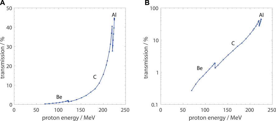
FIGURE 1. Transmission from cyclotron to target position at the fixed beamline in the experimental area of the UPTD as a function of proton energy panel (A): linear scale, panel (B): logarithmic scale). The transmission was determined by measurements of the absolute beam current using a PTW 34070 Bragg peak chamber. The distinct steps are due to the switching of the degrader material (aluminum, carbon, beryllium) depending on the energy range.
Several facilities and research groups make use of 3D-printed range modulators to create SOBPs for radiobiological or dosimetric experiments with protons or heavy ions [1220–23]. These modulators consist of periodically arranged pins or ridges which represent different thicknesses to specific fractions of the beam and therefore modulate the energy and range distribution. The shape of the pins or ridges can be optimized to produce a desired depth dose distribution, e.g., an SOBP. The period should be considerably smaller than the size of the beam spot for an optimal modulation.
Usually the geometry of such modulators is optimized based on a pristine laterally integrated Bragg curve. For modulators optimized in this way, however, in order to obtain a flat central depth dose profile an extended radiation field is required. This is illustrated in Figure 2 where dose distributions in water for 220 MeV protons with and without a range modulator optimized to produce a 5 cm SOBP are shown. The dose distributions were calculated using the FLUKA Monte Carlo code [2425] and a dedicated sub-routine for implementation of the modulator geometry [26].
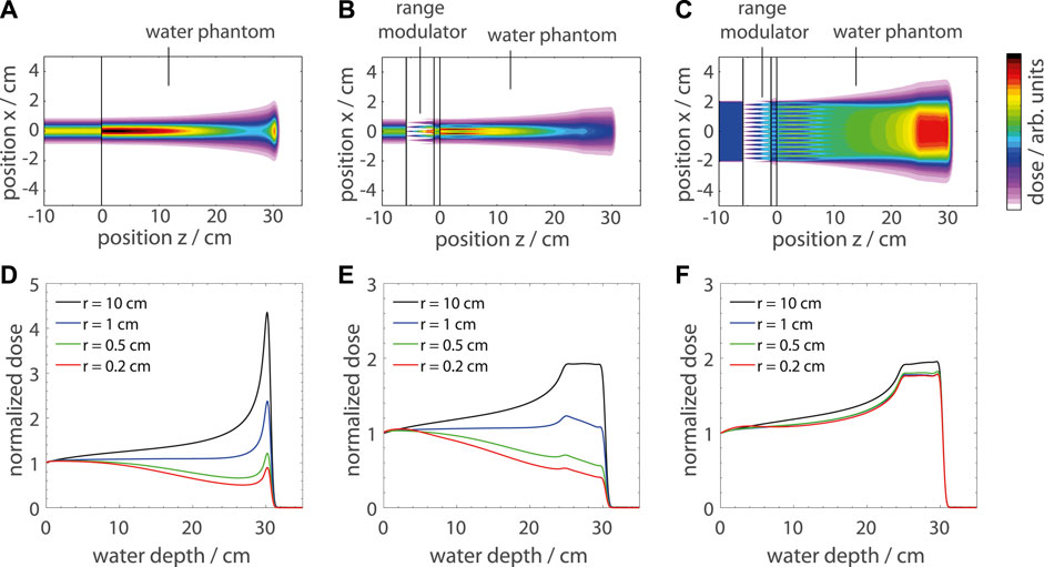
FIGURE 2. Dose distributions for 220 MeV protons impinging on a water phantom with and without a range modulator in front calculated using the FLUKA Monte Carlo code. The upper panels (A–C) show 2D dose distributions in air and in the water phantom and the lower panels (D–F) show 1D profiles normalized to the entrance dose for different integration radii (0.2 cm − 10 cm). Panel (A) and (D) show the dose distribution of a pristine pencil beam, (B) and (E) of a modulated pencil beam and (C) and (F) of a modulated broad beam.
The upper panels show 2D dose distributions before and inside the water phantom and the lower panels show 1D depth profiles in water for different cylindrical integration radii (2 mm − 10 cm). Figures 2A,D show the dose distribution of a pristine 220 MeV proton pencil beam (8 mm full width at half maximum) without modulation. It can be observed that the lateral size of the beam widens up strongly during traversal through the water phantom due to lateral scattering. This causes the Bragg peak, which is very pronounced in the laterally integrated depth dose profile, to be attenuated considerably for smaller integration radii. Figure 2B,E show the corresponding dose distribution for the same beam, but with a range modulator in front of the water phantom. As visible in Figure 2B, the edge scattering effects at the range modulator pins cause a ripple in the dose distribution, which again blurs out until the SOBP depth (as studied in detail by Charuchinda et al. [26]). In Figure 2E one can observe that the laterally integrated depth dose profile shows a flat SOBP while the central dose profiles (calculated from smaller integration radii) get a negative slope towards the distal edge due to multiple Coulomb scattering. Figures 2C,F show the corresponding dose distributions for the same modulator but with an extended irradiation field of 4 × 4 cm2. For this configuration the SOBP is flat for all integration radii because there is a lateral scattering equilibrium all along the beam path.
Basically all previous experiments applying such range modulators used extended fields, either produced by scattering or scanning of pencil beams. Scanning of the beam is not possible at our fixed beamline and the irradiation fields should be kept small to achieve highest dose rates. Therefore, we tested a different approach using the central depth dose profile (e.g., red curve in Figure 2D) instead of the laterally integrated depth dose profile as input for the optimization of the modulator geometry. Accordingly, also the effect of collimators, which restrict the phase space of the proton beam and modify its depth dose profile, can be taken into account during the optimization of the modulator geometry by including it already during the measurement of the reference depth dose profile. In this work, the reference dose profiles for the different configurations were obtained by measurements with small detectors, a PTW PinPoint 3D ionization chamber (model 31022) and a PTW microdiamond detector (model 60019) scanned along the central axis (see Section 2.4). It should be noted that in the setup used for measurement of the unmodulated central dose profile used as reference, the distances and the configuration (especially collimator position) should be as close as possible to those in the final setup that is used for SOBP irradiations.
The two experimental setups intended for FLASH irradiation within proton SOBPs that were realized within this work are shown schematically in Figure 3. They were designed to be set up quickly and in a robust way, using PMMA absorbers instead of water.
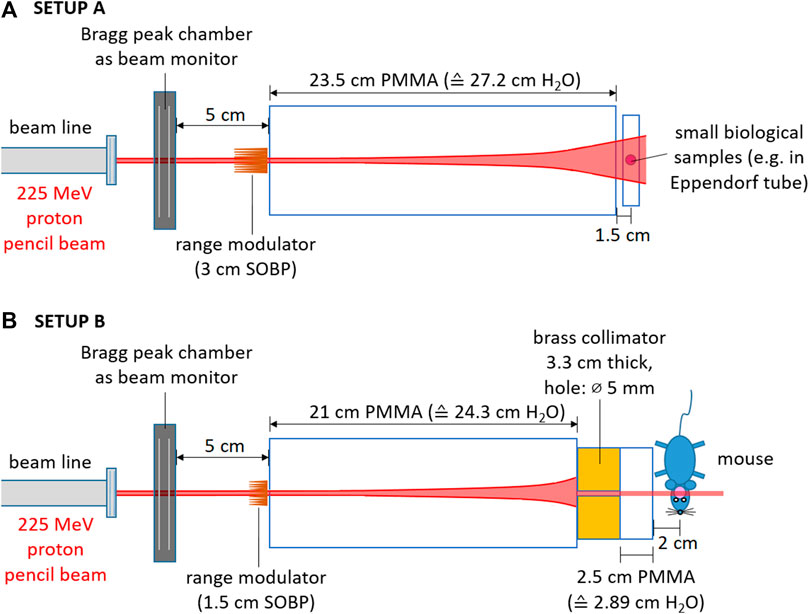
FIGURE 3. Experimental setups for proton SOBP irradiations at ultra-high dose rate using 3D-printed range modulators. Panel (A): SETUP (A) irradiation of small samples with a homogeneous dose in the center of a 3 cm SOBP. Panel (B): SETUP (B) irradiation of partial volumes of small animals with a sharply collimated 1.5 cm SOBP.
Figure 3A shows SETUP A which is intended for irradiation of small biological samples with dimensions
Figure 3B shows SETUP B which can be used for irradiation of partial volumes (e.g., partial brain irradiation) of small animals with a 1.5 cm long SOBP at ultra-high dose rate while surrounding tissues and organs are spared. However, for 225 MeV protons the distal edge has an extension of
Dose profiles for pristine and for modulated proton beams for both setups were obtained. Different detectors were used to characterize the dose distributions.
The IBA Giraffe multi-layer ionization chamber [27] was used for measuring laterally integrated depth dose profiles of SETUP A.
For measurements of central dose profiles of SETUP A, a PTW water phantom (model 41023) together with a PTW PinPoint 3D ionizaton chamber (model 31022) read out by a PTW UNIDOS Tango electrometer was used. For large water depths, a PMMA range shifter with 7.6 cm water equivalent thickness was placed in front of the water phantom. A transmission ionization chamber built-in the beamline (model 34058 by PTW) served as reference detector [5].
For the collimated fields of SETUP B, a PTW microdiamond detector (model 60019) was used (as, e.g., also by Togno et al. [28]) which allows dose profile measurements with micrometer resolution. Instead of scanning it in beam direction through a water phantom, the microdiamond was placed in a PMMA plate at 5 mm geometrical depth and scanned along the lateral direction (using a linear stage by OWIS) to detect the central dose maximum for each measurement depth. The different measurement depths were realized by placing PMMA plates of varying thickness in between the collimator and the microdiamond detector and simultaneously increasing the distance between both. The ionization current signal of the diamond detector was read out by a PTW UNIDOS electrometer (model 10001) and logged together with the lateral position.
The different detectors, their characteristics and their field of application are summarized in Table 1
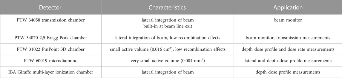
TABLE 1. Detectors used for experimental characterization of the proton beam at UPTD and the dose distributions produced by 3D-printed range modulators.
The characterization of the dose profiles was done at moderate proton beam currents (
The range modulators designed for the present study have pins with a pyramid shape and a square base as the basic geometry which are periodically repeated. Protons passing through different thicknesses of the pins lose a different amount of energy and therefore result in Bragg peaks with different ranges. The pin shape and thereby the weighted superposition of these shifted Bragg curves can be optimized to result in a homogeneous SOBP.
The optimization principle behind the modulators optimized and produced at GSI is described in detail by Simeonov et al. [12] and Holm et al. [21]. The optimization of the modulators for the present work is illustrated in Figure 4. Each of Figures 4A–C shows one of the different modulators that was produced and tested within this work. The blue curves are the measured pristine depth dose profiles which are the basic input for the optimization. One modulator was optimized on the measured laterally integrated depth dose profile (Figure 4A) for SETUP A, another one on the measured central depth dose profile (Figure 4B) for SETUP A and a third one on the measured central dose profile of a collimated beam (Figure 4C) for SETUP B. The yellow areas mark the depth range in which the optimizer (chi-square minimization) should create a homogeneous dose. The red curves show the optimized SOBPs and the green symbols indicate the optimized weights for the shifted Bragg peaks, which are basically shifted copies of the blue curves (pristine Bragg peaks). Figure 4D compares for the three modulators the profiles of the pins whose shape is based on these optimized weights. The weights have gap after a first high weight in order to sharpen the distal fall-off of the SOBP and are normalized to have a sum of 1. The square pyramids were then exported as .stl files and printed on a 3DSystems ProJet MJP 2500 Plus 3D-printer using VisiJet M2S-HT250 as printing material and VisiJet M2 SUP as support material. The printing material has a water equivalent density of 1.162 g/cm3 (determined by previous measurements with proton beams). The modulator structures were embedded in a frame for better stability and have a 2 mm thick base plate on which the pins are standing. The pins were arranged as a 16 × 16 matrix with a 3 mm period (Figure 4D).
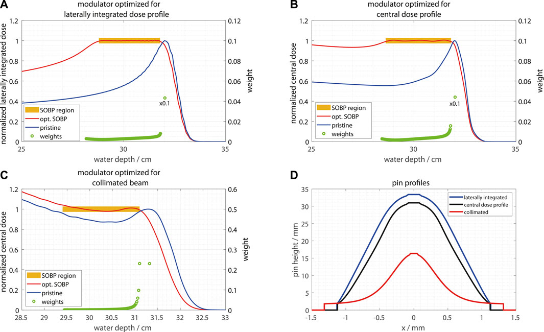
FIGURE 4. Depth dose profiles for the different range modulators optimized and produced at GSI within this work panel (A–C) and their pin geometries (panel (D)). The blue curves in panel (A–C) show the pristine Bragg curves used as input for the optimization, the red curves show the optimized SOBPs for the yellow marked region and the green symbols show the weights of the shifted Bragg curves. In panel (A) and (B), the first (deepest) weight was scaled down by a factor of 0.1 for better visibility of the other weights.
At TIFPA/UniTn, a range modulator for SETUP B was optimized combining previously calculated look-up tables of depth dose profiles with the solution of a linear system using a dedicated script. The look-up tables were generated with TOPAS Monte Carlo simulations [32], by reproducing the beam properties and the geometry of the experimental setup and scoring the resulting depth dose distribution in a voxelized water phantom (voxel size comparable to the microdiamond detector volume of 0.004 mm3) and checking that it matches with the previously measured depth dose profile. Separate simulations were then performed for the beam traversing layers of increasing thicknesses of water, resembling the different layers of the range modulator pin. A total of 21 layers in 0.5 mm steps was simulated. The weights of the different shifted Bragg curves were optimized to produce a flat SOBP. The resulting weights were then converted into a pin geometry and scaled by the water-equivalent thickness of the printer material. The pins were arranged in a matrix of adjacent pins with 3 mm edge length at the base. After verification with another TOPAS simulation, the modulator geometry was converted into a .stl file and 3D-printed at UniTn using the PolyJet technique, a type of additive manufacturing, using a Stratasys J750 3D printer, which is known for its exceptional printing capabilities (see Figure 5). This approach has been extensively developed and tested at UniTn for printing samples with very complicated geometry [10].
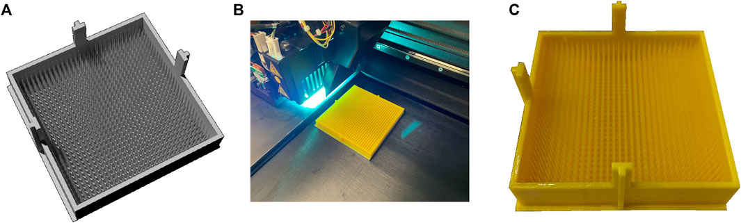
FIGURE 5. Schematic showing the manufacturing process of the range modulator at UniTn. Panel (A): range modulator CAD file, panel (B): manufacturing of the range modulator, panel (C): 3D-printed range modulator.
To achieve the required level of precision, the printer was set to high-quality mode, resulting in a layer height resolution of 14 μm, meaning that each successive layer of photopolymer was only 14 μm thick. This level of resolution is critical for creating small, intricate structures like the pins of the range modulator. In addition, the dimensional accuracy of the printer was set to 100 μm to ensure that the final product was very close to the intended dimensions. The range modulator was printed with pins aligned vertically (in the z-direction) with respect to the printer head. This alignment was critical for ensuring that the pins were properly formed and that the final product would function as intended. The Vero Yellow RGD836 printing material was chosen due to its excellent mechanical properties and chemical resistance. To ensure that the very thin pins were not damaged during printing, a glossy surface finishing mode was used, which reduced the need for supporting materials that could have caused the pins to break during removal. Like the GSI modulators, also the TIFPA/UniTn modulator has a 2 mm thick base plate on which the pins were printed.
The most notable difference in the two optimization methods is how to obtain the shifted Bragg curves used as input for optimization of the modulator geometry. In contrast to the fast numerical approach with (reasonable) simplifications used by GSI, TIFPA/UniTn follows a full Monte Carlo approach to have maximum accuracy already at the stage of optimization but at the cost of increased calculation time. The Monte Carlo approach could be of special interest for complex setups, e.g., with multiple collimators and air gaps, where a simple 1D approximation might not be accurate enough.
The most common descriptor of radiation quality is the dose averaged LET (LETD) in water [33]. Since this quantity is not straightforward to measure, a common method is to calculate it via radiation transport calculations, typically using a Monte Carlo code. Monte Carlo simulations to calculate profiles of LETD in water for the different setups were carried out using the FLUKA Monte Carlo code (version 2021 2.9) [2425] and the TOPAS toolkit which is based on Geant4 [32].
In FLUKA, the modulator geometries were implemented in the simulations with a dedicated sub-routine [26]. LET spectra in water taking into account all primary and secondary charged particles were scored with the USRYIELD card. From these spectra, the dose averaged LET was calculated offline by averaging.
In TOPAS, the modulator geometry was implemented in the simulation by means of a custom TOPAS extension. The dose-average LET taking into account primary and secondary protons was retrieved with the standard TOPAS LET scorer, by setting the LET computation to look up the electronic stopping power of water for the pre-step proton energy.
The different modulators designed and produced within this work were characterized in detail experimentally and by means of Monte Carlo simulations.
Figure 6 shows measured laterally integrated depth dose profiles (Figures 6A,B) measured with the IBA Giraffe detector as well as central depth dose profiles measured with a PTW PinPoint 3D ionization chamber (radius of sensitive volume: 1.45 mm) in a water phantom (Figures 6C,D) for SETUP A. The measurements were performed for the pristine 225 MeV proton beam and two types of range modulators optimized to produce an SOBP with 3 cm modulation width (SETUP A). One modulator was optimized in the conventional way using the laterally integrated dose profile of the pristine beam (blue curve in Figures 6A,B) as input for the optimization of the modulator geometry, while the other one was optimized using the central depth dose profile (blue curve in Figures 6C,D), see Figure 4. The conventionally optimized modulator was added to the present study in order to verify the expectation that the SOBP is not flat when irradiated with a static pencil beam (shown in Figure 2) while the modulator optimized on the central dose profile is the one intended for the actual experimental setup.
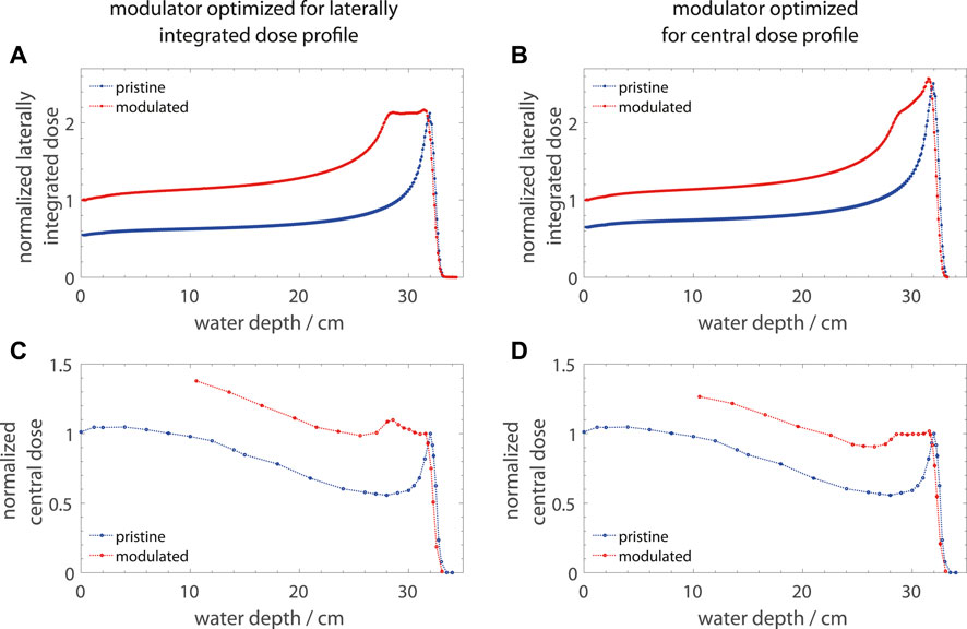
FIGURE 6. Measured laterally integrated panel (A) and (B) and central depth dose profiles panel (C) and (D) for 225 MeV protons for two range modulators optimized for SETUP A (one for laterally integrated and the other one for the central dose profile). Panel (A) and (C) show data for a modulator that was optimized for the laterally integrated depth dose profile of the pristine beam while the modulator for panel (B) and (D) was optimized using the central depth dose profile.
The obtained depth dose profiles are in line with the general picture shown in Figure 2 which was obtained by FLUKA simulations. As visible in Figures 6A,C, the optimization on the laterally integrated depth dose profile of the pristine beam creates a flat SOBP in the laterally integrated profile but introduces a tilted SOBP in the central depth dose profile which would be relevant for the irradiation of samples with a static pencil beam. By using the central depth dose profile of the pristine beam for optimization (Figures 6B,D), the central depth dose profile gets a flat SOBP which is sufficient to irradiate samples while the laterally integrated profile gets a positive slope towards the distal end. Therefore, such a range modulator can be considered as a specialized solution for SOBP irradiations with static pencil beams.
Figure 7 shows central depth dose profiles for SETUP B measured behind the collimator (see Figure 3B). A PTW microdiamond detector was used to measure lateral profiles at different PMMA depths and the dose maxima in these lateral profiles give the central depth dose profile. These measurements were performed for the pristine 225 MeV proton beam and for two range modulators optimized and produced independently at two different institutes (GSI and TIFPA/UniTn).
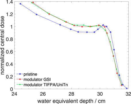
FIGURE 7. Measured central depth dose profiles for 225 MeV protons for two range modulators optimized for SETUP (B). The pristine Bragg peak (blue curve) was used for optimization of the modulators. One modulator (red curve) was optimized and produced at GSI in Darmstadt, Germany and the other one (green curve) at TIFPA/UniTn in Trento, Italy. A brass collimator with 5 mm hole was placed at 24 cm water equivalent depth. Behind the collimator, the depth dose profiles were measured with a PTW microdiamond detector in PMMA plates. The PMMA depths were re-scaled to water equivalent depths.
In the central depth dose profile for the pristine beam (Figure 7, blue curve) one can observe that the Bragg peak almost disappears due to the presence of the collimator at 24 cm water equivalent depth. However, a flat depth dose distribution right before the end of the range that is comparable with a classical SOBP can be produced even for this sharply collimated configuration (red and green curves in Figure 7) while the two modulators that were optimized and produced independently at GSI and TIFPA/UniTn produce comparable depth dose profiles.
A general difference between SETUP A and SETUP B are the produced lateral dose profiles. While SETUP A is designed to deliver a homogeneous dose to a small sample, SETUP B is supposed to produce a sharply confined radiation field to irradiate partial volumes in small animals and spare surrounding organs and tissues. Comparable experiments to SETUP B with conventional dose rates have been established at UPTD [1634] where a 90 MeV proton beam is degraded in plastic absorbers, collimated to a size of a few millimeters and stopped in the center of a mouse brain.
Figure 8 compares the lateral dose distributions of the two setups (SETUP A and SETUP B) at the SOBP center depth (29.5 cm water equivalent depth). The lateral dose profiles were measured with the PTW microdiamond detector behind PMMA slabs as described above. The noise on the profiles is due to the low beam currents used for the lateral scans.
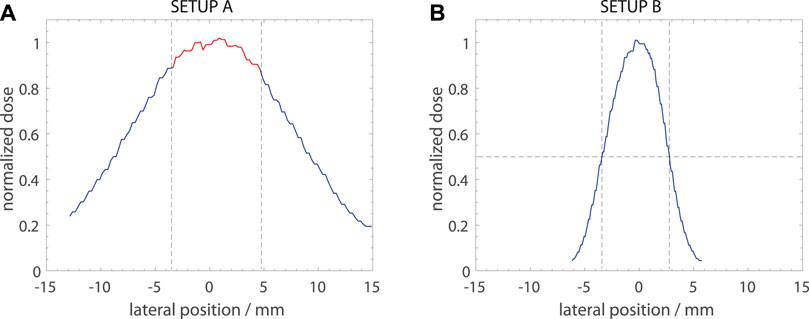
FIGURE 8. Measured lateral dose profiles at the SOBP center for the SETUP A panel (A) and SETUP B (panel (B)). The dose profiles were measured with a PTW microdiamond detector in a PMMA plate scanned along the lateral direction with a linear axis drive. The water equivalent depth was 29.5 cm for both measurements. The dashed lines in panel (A) indicate the useable field size (dose inhomogeneity
The lateral dose profile for SETUP A (Figure 8A) shows that samples with sizes of 8–9 mm can be irradiated with a relatively homogeneous dose (±5%), as marked by the red line. This is a sufficient field size for, e.g., 0.5 mL Eppendorf tubes (inner tube diameter of 6.5 mm). If a larger field size is required the sample can be positioned at a larger distance, however, at the cost of a lower dose rate. In contrast to this broad field, the lateral dose profile of SETUP B (Figure 8B) is sharply collimated. The dose drops down to 50% of the maximum value at a lateral distance from the center of
Monte Carlo simulations using the FLUKA and TOPAS Monte Carlo codes were performed to study LETD profiles. Figure 9 shows calculated LETD profiles together with the measured central depth dose profiles for the two irradiation setups (SETUP A and SETUP B).
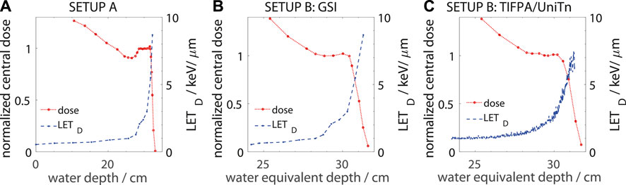
FIGURE 9. Measured central depth dose profiles for 225 MeV protons for range modulators optimized for SETUP A (panel (A)) and SETUP B (panel (B) and (C)) together with Monte Carlo calculated LETD profiles in water. Panel (B) shows the results for the modulator for SETUP B optimized and manufactured at GSI, Darmstadt and panel (C) shows the modulator optimized and manufactured at TIFPA/UniTn, Trento. The LETD profiles in panel (A) and (B) were calculated using the FLUKA Monte Carlo code while for the LETD profile in panel (C) was obtained from TOPAS/Geant4 simulations. For SETUP A, the depth dose profile was measured in water while for SETUP B they were measured in PMMA plates and converted to water equivalent depth.
The LETD profiles have a shape that is typical for proton SOBPs. At the entrance channel moderate LETD values below 1 keV/μm can be observed while it gets elevated to
Since the experimental setups described in this work are intended for FLASH irradiations, the maximum dose rates that can be reached in the SOBP region are also important to consider. From the transmission data in Figure 1, the maximum available beam current at the fixed beamline in the experimental room of UPTD for 225 MeV protons can be calculated as 223 nA (44.6% of 500 nA cyclotron current), corresponding to 1.39 × 10¹² protons per second.
The maximum dose rates that were reached in dosimetric tests, where the dose was measured in an irradiation pulse of 100 m using a PinPoint 3D ionization chamber positioned on the central axis at the central depth of the SOBP (where the relative dose profiles in Figures 6, 7, 8, and 9 are normalized to), were 610 Gy/s for SETUP A and 405 Gy/s for SETUP B. The about 30% lower dose rate in SETUP B compared to SETUP A is due to the additional collimation which cuts out protons coming at large angles. These dose rates are clearly high enough for FLASH experiments and with both setups even large doses up to 100 Gy can be applied with irradiation times far below 500 m, allowing studies of the FLASH effect at highest doses (as investigated previously with electrons [38]). The applied dose can be adjusted by the pulse length which at the fixed beamline at UPTD can be set with millisecond accuracy.Low dose rates in the order of 10 Gy/min could be reached as well by simply reducing the beam current. When changing the beam current, no change of the beam properties (e.g., position or spot size) was detected. Therefore, reference irradiations are possible without any changes to the setups.
Range modulators for SOBP irradiations at the static proton beamline in the experimental room of UPTD using a 225 MeV proton beam were designed, produced and tested experimentally. A new concept for the optimization of range modulators for static pencil beams and in presence of collimators, based on the central depth dose profiles as input into the optimization process, was introduced and shown to work well. The depth and lateral dose profiles were characterized in detail by measurements using a PinPoint chamber and a microdiamond detector. Two modulators, independently optimized and produced at two different institutes (GSI, Darmstadt, Germany and TIFPA/UniTn, Trento, Italy) were compared and found equivalent in terms of SOBP flatness and field characteristics.
Dose rates in the center of the SOBPs up to 610 Gy/s and 405 Gy/s were reached for the two new experimental setups, which is higher than what was possible with the previously used irradiation setup at the entrance channel of a pristine 225 MeV proton beam.
In addition to the dosimetric characterization, LETD profiles were obtained by means of Monte Carlo simulations and found to compare well with typical clinical proton SOBPs.
The newly produced range modulators will allow future proton FLASH experiments in the SOBP at UPTD with two different experimental setups.
The raw data supporting the conclusion of this article will be made available by the authors, without undue reservation.
FH, EBe, and JP designed the present study. CS, DM, NP, FT, and UW designed and produced the range modulators. FH, EBe, EBo, SG, and JP designed and built the experimental setups and performed the dosimetric characterization. FH and FT performed the Monte Carlo simulations. FH compiled the initial draft of the manuscript. All authors contributed to the article and approved the submitted version.
The range modulator studies performed in Trento were partially supported by the FRIDA project, funded by INFN CSN5.
The authors would like to thank Mabroor Ahmed from Helmholtz Center Munich for providing the software controlling the linear axis and electrometer readout used for measuring the lateral dose profiles. Warisara Charuchinda from GSI is acknowledged for providing the FLUKA routines for loading the modulator geometries. Remo Cristoforetti, now at DKFZ in Heidelberg, is acknowledged for the preliminary work performed on range modulator optimization in the Trento group. Jozef Bokor from IBA is acknowledged for providing helpful information concerning the transmission of the proton therapy system at UPTD.
The authors declare that the research was conducted in the absence of any commercial or financial relationships that could be construed as a potential conflict of interest.
All claims expressed in this article are solely those of the authors and do not necessarily represent those of their affiliated organizations, or those of the publisher, the editors and the reviewers. Any product that may be evaluated in this article, or claim that may be made by its manufacturer, is not guaranteed or endorsed by the publisher.
1. Favaudon V, Caplier L, Monceau V, Pouzoulet F, Sayarath M, Fouillade C, et al. Ultrahigh dose-rate flash irradiation increases the differential response between normal and tumor tissue in mice. Sci Transl Med (2014) 6:245ra93. doi:10.1126/scitranslmed.3008973
2. Vozenin M-C, Hendry J, Limoli C. Biological benefits of ultra-high dose rate flash radiotherapy: Sleeping beauty awoken. Clin Oncol (2019) 31:407–15. doi:10.1016/j.clon.2019.04.001
3. Limoli CL, Vozenin M-C. Reinventing radiobiology in the light of flash radiotherapy. Annu Rev Cancer Biol (2023) 7:1–21. doi:10.1146/annurev-cancerbio-061421-022217
4. Helmbrecht S, Baumann M, Enghardt W, Fiedler F, Krause M, Lühr A. Design and implementation of a robust and cost-effective double-scattering system at a horizontal proton beamline. J Instrument (2016) 11:T11001. doi:10.1088/1748-0221/11/11/T11001
5. Beyreuther E, Baumann M, Enghardt W, Helmbrecht S, Karsch L, Krause M, et al. Research facility for radiobiological studies at the university proton therapy dresden. Int J Part Ther (2018) 5:172–82. doi:10.14338/IJPT-18-00008.1
6. Henthorn NT, Sokol O, Durante M, De Marzi L, Pouzoulet F, Miszczyk J, et al. Mapping the future of particle radiobiology in Europe: The inspire project. Front Phys (2020) 8. doi:10.3389/fphy.2020.565055
7. Beyreuther E, Brand M, Hans S, Hideghéty K, Karsch L, Leßmann E, et al. (2019). Feasibility of proton flash effect tested by zebrafish embryo irradiation. Radiother Oncol 139, 46–50. doi:10.1016/j.radonc.2019.06.024
8. Jansen J, Knoll J, Beyreuther E, Pawelke J, Skuza R, Hanley R, et al. Does flash deplete oxygen? Experimental evaluation for photons, protons, and carbon ions. Med Phys (2021) 48:3982–90. doi:10.1002/mp.14917
9. Karsch L, Pawelke J, Brand M, Hans S, Hideghéty K, Jansen J, et al. Beam pulse structure and dose rate as determinants for the flash effect observed in zebrafish embryo. Radiother Oncol (2022) 173:49–54. doi:10.1016/j.radonc.2022.05.025
10. Mora S, Pugno NM, Misseroni D. 3d printed architected lattice structures by material jetting. Mater Today (2022) 59:107–32. doi:10.1016/j.mattod.2022.05.008
11. Simeonov Y, Weber U, Penchev P, Ringbæk TP, Schuy C, Brons S, et al. 3d range-modulator for scanned particle therapy: Development, Monte Carlo simulations and experimental evaluation. Phys Med Biol (2017) 62:7075–96. doi:10.1088/1361-6560/aa81f4
12. Simeonov Y, Weber U, Schuy C, Engenhart-Cabillic R, Penchev P, Durante M, et al. Monte Carlo simulations and dose measurements of 2d range-modulators for scanned particle therapy. Z für Medizinische Physik (2021) 31:203–14. doi:10.1016/j.zemedi.2020.06.008
13. Simeonov Y, Weber U, Schuy C, Engenhart-Cabillic R, Penchev P, Flatten V, et al. Development, Monte Carlo simulations and experimental evaluation of a 3d range-modulator for a complex target in scanned proton therapy. Biomed Phys Eng Express (2022) 8:035006. doi:10.1088/2057-1976/ac5937
14. Liu R, Charyyev S, Wahl N, Liu W, Kang M, Zhou J, et al. An integrated physical optimization framework for proton stereotactic body radiation therapy flash treatment planning allows dose, dose rate, and linear energy transfer optimization using patient-specific ridge filters. Int J Radiat Oncol Biol Phys (2023) 116:949–59. doi:10.1016/j.ijrobp.2023.01.048
15. Barna S, Meouchi C, Resch AF, Magrin G, Georg D, Palmans H. 3d printed 2d range modulators preserve radiation quality on a microdosimetric scale in proton and carbon ion beams. Radiother Oncol (2023) 182:109525. doi:10.1016/j.radonc.2023.109525
16. Suckert T, Müller J, Beyreuther E, Azadegan B, Brüggemann A, Bütof R, et al. High-precision image-guided proton irradiation of mouse brain sub-volumes. Radiother Oncol (2020) 146:205–12. doi:10.1016/j.radonc.2020.02.023
17. Kupfer T, Lehmann J, Butler DJ, Ramanathan G, Bailey TE, Franich RD. Commissioning of a ptw 34070 large-area plane-parallel ionization chamber for small field megavoltage photon dosimetry. J Appl Clin Med Phys (2017) 18:206–17. doi:10.1002/acm2.12185
18. Berger M, Coursey J, Zucker M. Estar, pstar, and astar: Computer programs for calculating stopping-power and range tables for electrons, protons, and helium ions (version 1.21). [Dataset] (1999).
19. Seltzer SM, Fernández-Varea JM, Andreo P, Bergstrom PM, Burns DT, Bronić IK, et al. Key data for ionizing-radiation dosimetry: Measurement standards and applications, icru report 90 (2016).
20. Tommasino F, Rovituso M, Bortoli E, La Tessa C, Petringa G, Lorentini S, et al. A new facility for proton radiobiology at the trento proton therapy centre: Design and implementation. Physica Med (2019) 58:99–106. doi:10.1016/j.ejmp.2019.02.001
21. Holm KM, Weber U, Simeonov Y, Krauss A, Jäkel O, Greilich S. 2d range modulator for high-precision water calorimetry in scanned carbon-ion beams. Phys Med Biol (2020) 65:215003. doi:10.1088/1361-6560/aba6d5
22. Titt U, Yang M, Wang X, Iga K, Fredette N, Schueler E, et al. Design and validation of a synchrotron proton beam line for flash radiotherapy preclinical research experiments. Med Phys (2022) 49:497–509. doi:10.1002/mp.15370
23. Kourkafas G, Bundesmann J, Denker A, Fanselow T, Heufelder J, Röhrich J, et al. Epd007 - a 3d range modulator for ultra-short proton flash irradiation. Physica Med (2022) 94:S64–S65. doi:10.1016/S1120-1797(22)01578-2
24. Ferrari A, Sala PR, Fassò A, Ranft J. FLUKA: A multi-particle transport code (2005). CERN-2005-10.
25. Böhlen T, Cerutti F, Chin M, Fassò A, Ferrari A, Ortega P, et al. The FLUKA code: Developments and challenges for high energy and medical applications. Nucl Data Sheets (2014) 120:211–4. doi:10.1016/j.nds.2014.07.049
26. Charuchinda W, Horst F, Simeonov Y, Schuy C, Penchev P, Poulsen P, et al. 3d range-modulators for proton therapy: Near field simulations with fluka and comparison with film measurements. J Phys Conf Ser (2023) 2431:012081. doi:10.1088/1742-6596/2431/1/012081
27. Bäumer C, Koska B, Lambert J, Timmermann B, Mertens T, Talla PT. Evaluation of detectors for acquisition of pristine depth-dose curves in pencil beam scanning. J Appl Clin Med Phys (2015) 16:151–63. doi:10.1120/jacmp.v16i6.5577
28. Togno M, Nesteruk K, Schäfer R, Psoroulas S, Meer D, Grossmann M, et al. Ultra-high dose rate dosimetry for pre-clinical experiments with mm-small proton fields. Physica Med (2022) 104:101–11. doi:10.1016/j.ejmp.2022.10.019
29. Gotz M, Karsch L, Pawelke J. A new model for volume recombination in plane-parallel chambers in pulsed fields of high dose-per-pulse. Phys Med Biol (2017) 62:8634–54. doi:10.1088/1361-6560/aa8985
30. Baack L, Schuy C, Brons S, Horst F, Voss B, Zink K, et al. Reduction of recombination effects in large plane parallel beam monitors for flash radiotherapy with scanned ion beams. Physica Med (2022) 104:136–44. doi:10.1016/j.ejmp.2022.10.029
31. Kranzer R, Schüller A, Bourgouin A, Hackel T, Poppinga D, Lapp M, et al. Response of diamond detectors in ultra-high dose-per-pulse electron beams for dosimetry at flash radiotherapy. Phys Med Biol (2022) 67:075002. doi:10.1088/1361-6560/ac594e
32. Perl J, Shin J, Schümann J, Faddegon B, Paganetti H. Topas: An innovative proton Monte Carlo platform for research and clinical applications. Med Phys (2012) 39:6818–37. doi:10.1118/1.4758060
33. Grün R, Friedrich T, Traneus E, Scholz M. Is the dose-averaged let a reliable predictor for the relative biological effectiveness? Med Phys (2019) 46:1064–74. doi:10.1002/mp.13347
34. Schneider M, Bodenstein E, Bock J, Dietrich A, Gantz S, Heuchel L, et al. Combined proton radiography and irradiation for high-precision preclinical studies in small animals. Front Oncol (2022) 12:982417. doi:10.3389/fonc.2022.982417
35. Kalholm F, Grzanka L, Traneus E, Bassler N. A systematic review on the usage of averaged let in radiation biology for particle therapy. Radiother Oncol (2021) 161:211–21. doi:10.1016/j.radonc.2021.04.007
36. Hahn C, Ödén J, Dasu A, Vestergaard A, Fuglsang Jensen M, Sokol O, et al. Towards harmonizing clinical linear energy transfer (let) reporting in proton radiotherapy: A European multi-centric study. Acta Oncologica (2022) 61:206–14. doi:10.1080/0284186X.2021.1992007,
37. Grün R, Friedrich T, Krämer M, Scholz M. Systematics of relative biological effectiveness measurements for proton radiation along the spread out Bragg peak: Experimental validation of the local effect model. Phys Med Biol (2017) 62:890–908. doi:10.1088/1361-6560/62/3/890
Keywords: proton therapy, range modulator, 3D-printing, spread out Bragg peak, FLASH effect, ultra-high dose rate
Citation: Horst F, Beyreuther E, Bodenstein E, Gantz S, Misseroni D, Pugno NM, Schuy C, Tommasino F, Weber U and Pawelke J (2023) Passive SOBP generation from a static proton pencil beam using 3D-printed range modulators for FLASH experiments. Front. Phys. 11:1213779. doi: 10.3389/fphy.2023.1213779
Received: 28 April 2023; Accepted: 26 June 2023;
Published: 04 July 2023.
Edited by:
Fabio Di Martino, Pisana University Hospital, ItalyReviewed by:
Vivek Maradia, Paul Scherrer Institut (PSI), SwitzerlandCopyright © 2023 Horst, Beyreuther, Bodenstein, Gantz, Misseroni, Pugno, Schuy, Tommasino, Weber and Pawelke. This is an open-access article distributed under the terms of the Creative Commons Attribution License (CC BY). The use, distribution or reproduction in other forums is permitted, provided the original author(s) and the copyright owner(s) are credited and that the original publication in this journal is cited, in accordance with accepted academic practice. No use, distribution or reproduction is permitted which does not comply with these terms.
*Correspondence: Felix Horst, ZmVsaXguaG9yc3RAb25jb3JheS5kZQ==
Disclaimer: All claims expressed in this article are solely those of the authors and do not necessarily represent those of their affiliated organizations, or those of the publisher, the editors and the reviewers. Any product that may be evaluated in this article or claim that may be made by its manufacturer is not guaranteed or endorsed by the publisher.
Research integrity at Frontiers
Learn more about the work of our research integrity team to safeguard the quality of each article we publish.