
95% of researchers rate our articles as excellent or good
Learn more about the work of our research integrity team to safeguard the quality of each article we publish.
Find out more
REVIEW article
Front. Phys. , 09 May 2023
Sec. Optics and Photonics
Volume 11 - 2023 | https://doi.org/10.3389/fphy.2023.1198457
This article is part of the Research Topic Acquisition and Application of Multimodal Sensing Information View all 12 articles
Polarization three-dimensional (3D) imaging technology has received extensive attention in recent years because of its advantages of high accuracy, long detection distance, simplicity, and low cost. The ambiguity in the normal obtained by the polarization characteristics of the target’s specular or diffuse reflected light limits the development of polarization 3D imaging technology. Over the past few decades, many shape from polarization techniques have been proposed to address the ambiguity issues, i.e., high-precision normal acquisition. Meanwhile, some polarization 3D imaging techniques attempt to extend experimental objects to complex specific targets and scenarios through a learning-based approach. Additionally, other problems and related solutions in polarization 3D imaging technology are also investigated. In this paper, the fundamental principles behind these technologies will be elucidated, experimental results will be presented to demonstrate the capabilities and limitations of these popular technologies, and finally, our perspectives on the remaining challenges of the polarization 3D imaging technology will be presented.
As an important approach for humans to record and perceive environmental information, traditional optoelectronic imaging techniques are increasingly ineffective due to the loss of high-dimensional information [1, 2]. With advancements in new sensors, data transmission, and storage, more information about the light field such as phase, polarization, and spectral information can be efficiently detected and recorded [3–6], which helps to construct a functional relationship between the reflected light information and the contour of the object surface to obtain 3D information. Currently, the 3D reconstruction technique has drawn widespread attention and achieved great progress in face recognition, industrial inspection, autonomous driving, and digital imaging [7–16].
Existing 3D imaging technologies can be divided into two major categories: active and passive techniques [17]. Generally, these methods vary in cost, hardware configuration, stability, running speed, and resolution. The active techniques use active illumination for 3D reconstruction such as time-of-flight (TOF), lidar 3D imaging, and structured light 3D imaging. Specifically, the TOF technique [18] employs an active emitter to modulate the light in the time domain and an optical sensor to collect the light scattered back by the object, and finally, it recovers depth information by calculating the time delay from the signal leaves the device and the signal returns to the device. The TOF technique has been widely used in commercial products like Kinect II, but the technology is susceptible to ambient light interference and limited by the temporal resolution of the signal system, so the achieved depth resolution is usually not high. The lidar 3D imaging [19] adopts the laser ranging principle to acquire system-target micro-surface element distance information, and then the 3D information of the target surface is obtained by mechanical scanning or beam deflection. Therefore, lidar 3D imaging has poor real-time performance for 3D imaging of large targets, and it is difficult to achieve popularity due to its complex mechanical structure, which leads to large system size and high cost. The structured light 3D imaging technology utilizes a projection device to actively project structured patterns. For the structured light 3D imaging, a one-to-one correspondence is constructed between points in the camera plane and those in the projection plane by decoding the captured contour images [20, 21], and camera calibration parameters are combined to obtain 3D point cloud data. Despite the advantage of high-precision imaging, the structured light 3D imaging technology still suffers from the problem of poor resistance to ambient light interference and decreasing accuracy with increasing detection distance.
The passive techniques with no active illumination for 3D reconstruction mainly include stereo vision and light field cameras. Specifically, the stereo-vision system [22] captures images from at least two different viewpoints and finds corresponding points from these images for 3D coordinate calculations based on triangulation. Because its reconstruction accuracy is inversely proportional to the length of the camera baseline, the stereo vision method is difficult to obtain high-precision 3D surface information in long-distance detection. The light field camera 3D imaging technique [23] acquires light source direction by embedding a micro-lens array between the lens and detector, thus obtaining 3D information under passive conditions; however, similar to stereo vision, this technique is limited by the distance between the micro-lens arrays, so it cannot realize long-distance 3D imaging and suffers from a low imaging accuracy.
With the increasingly urgent demand for long-range, high-precision, and high-dimensional target information in many fields such as security surveillance, deep-space exploration, and target detection, 3D imaging with higher performance through deep mining and decoding the multi-dimensional physical information of the optical field has become the mainstream research direction. Since the 1970s, domestic and foreign researchers have investigated the utilization of polarization information for 3D shape recovery of target surfaces, and they have developed a series of polarization 3D imaging methods [24–27]. The core of these methods is to exploit Fresnel laws to establish the functional relationship between reflected light polarization characteristics and three-dimensional contour. Benefiting from the special reconstruction mechanism, polarization 3D imaging technology has the advantages of high reconstruction accuracy, simple detection equipment, and non-contact 3D reconstruction. Therefore, this paper will primarily focus on representative Shape from Polarization (SfP) techniques. This paper elucidates the principles of polarization 3D imaging based on specular reflection and diffuse reflection and presents some typical technical theories and their experimental results.
The rest of the paper is organized as follows: Section 2 introduces the basics of polarization 3D imaging based on specular reflection and diffuse reflection. Section 3 discusses the principles of SfP techniques along with some experimental results to demonstrate their performances; Section 4 presents our perspectives on the challenges of polarization 3D imaging technology; Section 5 summarizes this paper.
Since the 3D contour of the target surface can be uniquely determined by the normal vector [28, 29], the polarization 3D imaging technology reconstructs the target 3D contour by obtaining the normal vector information of the surface micro-surface element. As shown in Figure 1A, the reflected light is detected by the detector through the polarizer when the incident light reaches the object surface and reflects [30]. The incident light, the object surface normal and the reflected light are in the same plane, ϕ is the angle of polarization (AoP), the transmission direction of the reflected light is z-axis positive direction under the assumption of orthographic projection. The object surface normal representation can be directly displayed in Figure 1B, where θ is the zenith angle of the object surface normal, and φ is the azimuth angle [31]. From the above analysis of the polarization 3D imaging process, the normal vector of the object surface based on the polarization characteristics of reflected light is expressed as
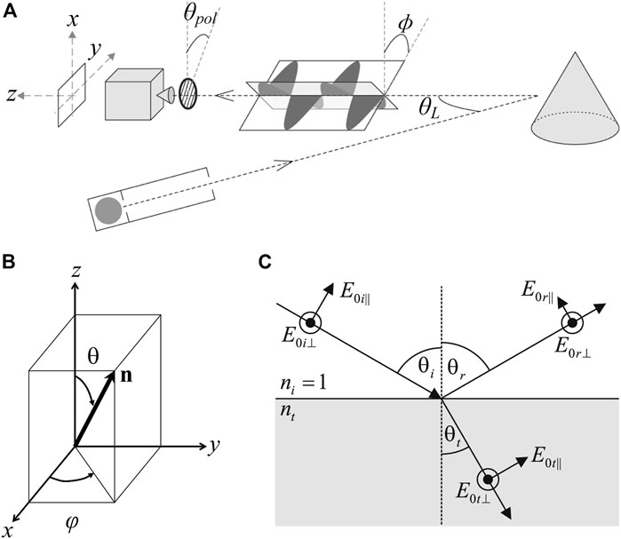
FIGURE 1. (A) The measurement process of polarization 3D imaging. Adapted from [30], with permission from IEEE. (B) The schematic of a normal vector. Reproduced/adapted from [31], with permission from IEEE. (C) The s- and p-components of reflected and refracted light. Reproduced from [30], with permission from IEEE.
According to Fresnel Laws, light reflection and refraction occur when unpolarized light arrives at the target surface, which causes a change in the polarization state of the incident light [32]. Polarization state changes are significantly different for reflected and refracted light, and they are expressed as [29, 31]:
where rs, rp, ts, and tp denote the reflection and transmission coefficients when decomposing a plane light wave into vertical and parallel components, i.e., s-component and p-component, respectively, as shown in Figure 1C. The reflection and transmission coefficients are defined as:
Since the polarization of the light emitted from the target surface differs in the reflected and refracted states, it is necessary to analyze the light state when it reaches the incident interface of different target surfaces, which provides a basis for selecting suitable polarization 3D reconstruction methods for different object surfaces. In 1991, Wolff provided a detailed classification and description of the types of light emitted from the target surface [28]. As shown in Figure 2A, Wolff classified the light into four categories: specular reflection light, diffuse reflection light, body reflection light (which can also be considered as special diffuse reflection light), and diffraction light. For body reflection light and body reflection light, they are generated with certain limitations and cannot reveal the true relationship between the target structure and the incident angle of the light, so the two types of light are usually not considered in recovering the 3D contours of the target and hence the existing polarization 3D imaging technology is mainly based on two different polarization characteristics of reflected light, namely, specular reflection and diffuse reflection. Specifically, as shown in Figure 2B, for smooth surfaces such as glass and metal, the reflected light is mainly displayed as specular reflection light with polarization information. For Lambertian objects like plaster, walls, and wood, it is usually assumed that the incident light enters the interior of the object, then scattered several times into unpolarized light, and finally transmitted into the air and received by the detector. Therefore, the selection of polarization 3D imaging methods based on different polarization characteristics is necessary for target surfaces of different materials, corresponding to two major methods based on specular reflection and diffuse reflection.
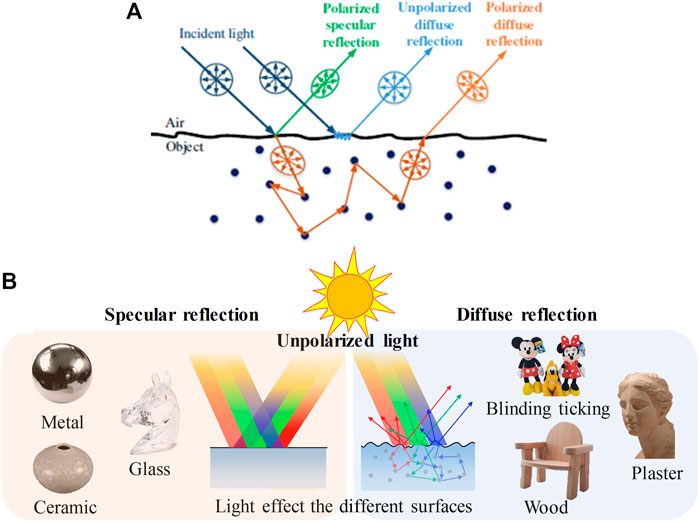
FIGURE 2. (A) Different types of reflected light from surfaces. Reproduced from [33], with permission from IEEE. (B) Polarization 3D imaging of different materials. Reproduced under CC-BY-4.0– [34] -http://journal.sitp.ac.cn/hwyhmb/hwyhmben/site/menu/20101220161647001.
As illustrated in Figure 1, the normal vectors of the target surface can be determined by the zenith angle θ and the azimuth angle φ. Therefore, to obtain accurate normal vector information in the study of polarization 3D imaging technology, it is necessary to accurately acquire the above two normal vector parameters. The following will analyze the problems of accurate normal vector acquisition based on specular reflection and diffuse reflection polarization characteristics, respectively.
Since specular and diffuse reflection light emitted from the object surface follow the laws of reflection and transmission, the relationship between DoP and the zenith angle is shown in Eq. 2. Figure 3 presents the characteristic curves of polarization versus zenith angle θ for specular and diffuse reflections, respectively. It can be seen from Figures 3A,B that in the process of solving the zenith angle based on specular reflection, a degree of polarization corresponds to two zenith angles θ, which are on both sides of the Brewster angle, causing the ambiguity of the zenith angle. In contrast, for the acquisition of the zenith angle based on diffuse reflection, the degree of polarization varies monotonically in the range of θ = [0°, 90°], indicating that the degree of polarization has a one-to-one correspondence with the zenith angle. Therefore, the solution to the zenith angle is a major challenge in polarization 3D imaging technology based on specular reflection.
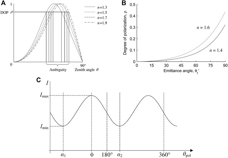
FIGURE 3. (A) The relationship between the degree of polarization and the incident angle with different refractive indices in polarization 3D imaging based on specular reflection. (B) The relationship between the degree of polarization and the incident angle with different refractive indices in polarization 3D imaging based on diffuse reflection. (C) The variation of light intensity information with the rotation angle of the polarizer. (A–C) Reproduced from [30], with permission from IEEE.
Meanwhile, according to Malus laws [35], the relationship between the light intensity and the polarizer rotation angle can be represented as:
where Imax and Imin denote the maximum and minimum light intensity received by the detector during rotation, respectively, θpol denotes the rotation angle of the polarizer, and ϕ denotes the polarization angle. Figure 3C shows the actual measured variation curve of diffuse light intensity based on the change in the polarizer rotation angle [30], and combined with Eq. 3, it can be seen that the light intensity I reaches the maximum value when the polarizer rotation angle is equal to ϕ or ϕ+180°. In addition, since the curve fitting approach requires large numbers of polarization images, which is complex and need intensive calculations, Wolff used Stokes vectors to obtain the angle of polarization, which requires only three images with polarization direction at 0o, 45o, and 90o. Due to no one-to-one correspondence between Imax and the angle of polarization ϕ, there is a multi-valued problem of φ = ϕ or φ = ϕ±π in the solution of the azimuth angle, which leads to ambiguity in the normal vector information obtained from polarization. Meanwhile, the ambiguity problem of the azimuth angle still exists in the polarization 3D imaging technology based on specular reflection, which can be expressed as φ = ϕ ± π/2.
Solving the ambiguity problem of the zenith angle θ and azimuth angle φ is the major focus and difficulty for researchers to develop polarization 3D imaging technology. Meanwhile, other problems in polarization 3D imaging, such as the inability to obtain absolute depth information and the difficulty of specular-diffuse reflection separation, need to be solved. For different types of reflected light, various methods have been proposed to solve these problems. In this paper, typical techniques and methods for addressing the ambiguous normal vector and other challenges will be reviewed from the perspectives of polarization 3D imaging technology based on specular reflection and diffuse reflection. Here, the techniques for eliminating the ambiguous normal vector and their characteristics are outlined in Table 1 to help readers better grasp the core of this paper.
Fresnel Laws indicate that the polarization characteristics of specular reflection light are easier to detect and more distinct than that of diffuse reflection light. Thus, researchers initially mainly used polarization characteristics of specular reflection information for 3D imaging of smooth surface materials like metals, transparent glass, and other specular targets. Many polarization 3D imaging techniques based on specular reflection have been proposed to solve the ambiguity problem of zenith and azimuth angles.
Miyazaki et al. [31] developed a method to solve the ambiguity problem of the zenith angle by rotating the object. By assuming that the target surface is smooth, closed, and non-shaded, they divided the target surface into the Brewster-Equatorial region (B-E), the Brewster-South Pole region (B-N), and the Brewster-Brewster regions (B-B) based on different values of polarization, as shown in Figures 4B,C. It was assumed that the B-E region contained a region that obscures the boundary so that a boundary point zenith angle θ = 90° existed in this region, and the zenith angle is determined by constraining the range of zenith angles of the points in the region θB<θ < 90°. For the B-N region containing a region of pixel points with a zenith angle θ = 0°, the constraint on the zenith angle of the region is 0° < θ < θB. For the solution to the ambiguity problem in the B-B region, polarization images of the target before and after rotation are obtained, as shown in Figure 4A. Based on the relationship between the difference in the DoP of the corresponding point before and after rotation, the first-order derivative of the DoP and the rotation angle, i.e., ρ(θ+Δθ)-ρ(θ)≈ρʹ(θ)Δθ, as well as the positive or negative sign of ρʹ(θ) can determine whether the zenith angle θ of the pixel points in the B-B region belong to 0° < θ < θB or θB < θ < 90°, as shown in Figures 4D,E.
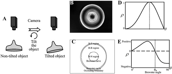
FIGURE 4. Schematic diagram of Miyazaki’s experiment. Reproduced from [31], with permission from IEEE. (A) The target information acquisition process with the target rotating at a small angle. (B) Polarization degree. (C) Areas divided by Brewster’s corner. (D) The relation curve between the polarization degree and the incident angle. (E) The derivative of polarization degree.
Since the rotational measurement method does not need to obtain the specific value of the rotation angle, calibration of the imaging system can be avoided. Even if there is an error in the reflected light polarization value, it does not affect the judgment of the Brewster angle in the first-order derivative of DoP, so the method has high robustness. However, multi-angle information acquisition and multiple measurements increase the complexity of the imaging system. Meanwhile, the existence of internal mutual reflection of transparent objects will result in a large error and poor reconstruction accuracy. Additionally, the method cannot image the moving target.
In 1995, Partridge et al. [36] analyzed the difference in DoP between reflected and transmitted light, and it was found that when the light was transmitted from the interior of the object, i.e., the emitted light was diffuse reflection light, its DoP corresponded to the zenith angle uniquely. Therefore, based on the target infrared radiation characteristics, Partridge adopted a far-infrared band detector for imaging to solve the zenith angle uniquely. However, random and systematic errors in the infrared detection system have a large impact on the imaging results.
Later, Miyazaki et al. [37] combined visible imaging with far-infrared imaging to obtain a unique solution of the zenith angle. To effectively detect the infrared information of the target, they used a hair dryer to heat the target surface and collected 36 infrared polarization images at different polarization angles by rotating the infrared polarizer to obtain the DoP of the target in the far-infrared band. By exploiting the unique correspondence between the DoP and the zenith angle in the far-infrared band, they avoided the ambiguity problem of the zenith angle in visible imaging. However, due to different types of visible and infrared imaging, the imaging system of the method is complex and costly, and there are problems in practical applications such as the need to match between images of different wavelengths, increasing the complexity of the application.
Inspired by the above methods, in 2012, Stolz et al. [38] proposed a method based on multi-spectral polarization processing to solve the ambiguity problem of the zenith angle and the problem of complex and expensive detection systems when obtaining information from multi-band systems. According to Cauchy’s dispersion formula, the refractive index decreases with the increase in the incident light wavelength in the visible wavelength [53]. Combining with Eq. 1 and Figure 3A, it can be seen that the refractive index is a parameter of the DoP and when the incident light wavelength increases, the corresponding zenith angle-polarization curve will also shift to the right, i.e., the Brewster angle shifts to a larger coordinate direction. By analyzing the variation curve of polarization with the zenith angle at different incident light wavelengths, the zenith angle ambiguity problem can be eliminated. Figure 5A illustrates the variation curves of DoP at different wavelengths, and the difference is exploited to solve the ambiguity of the zenith angle as follows: 1) Calculate the DoP at two different wavelengths (refractive index) pλ1 and pλ2 (λ1 > λ2), respectively; 2) Estimate the variability of polarization at different wavelengths Δp = pλ2-pλ1. 3) If Δp is larger than zero, the zenith angle θ = θ1; otherwise, θ = θ2. As shown in Figures 5B–D, Stolz et al. performed an experimental validation, and the result demonstrated that the method could realize undistorted 3D reconstruction of transparent targets. Additionally, the method can achieve accurate reconstruction acquisition for targets with local gradient mutations, providing an important reference for studying polarization 3D imaging techniques for complex target surfaces. However, because of the acquisition of intensity information in multiple bands, this method requires active illumination and cannot image in real time.
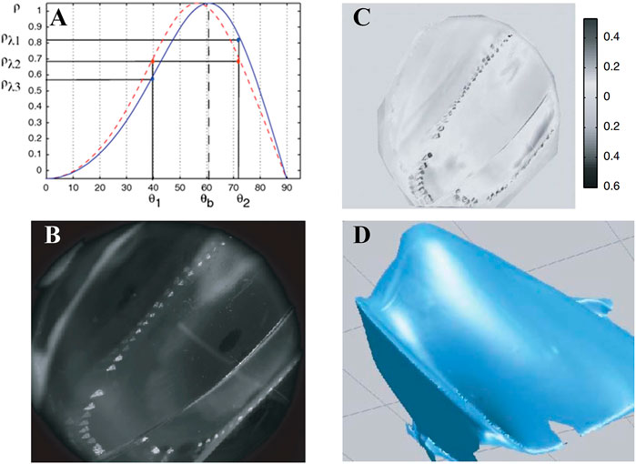
FIGURE 5. 3D reconstruction of transparent targets with a partial high slope. Reproduced under CC-BY-4.0- [38] - https://opg.optica.org/ol/fulltext.cfm?uri=ol-37-20-4218&id=243204. (A) The DoP curve at different incident light wavelengths. (B) Intensity image. (C) Polarization degree. (D) 3D reconstruction result.
Hao and Zhao et al. [41, 39] also conducted an in-depth study on multi-spectral polarization information, and they proposed a method for solving the incidence angle and refractive index simultaneously by using multi-spectral polarization characteristics of the target, which realized polarization 3D reconstruction of highly reflective non-textured nonmetallic targets. Besides, they added wavelength information to the relationship between the zenith angle and DoP by using Cauchy’s dispersion formula, so the problem of solving the zenith angle was transformed into a nonlinear least-squares problem. The utilization of spectral and polarization information effectively separates and suppresses stray light on the target surface, further improving the accuracy of target 3D reconstruction. The reconstruction results are illustrated in Figure 6.
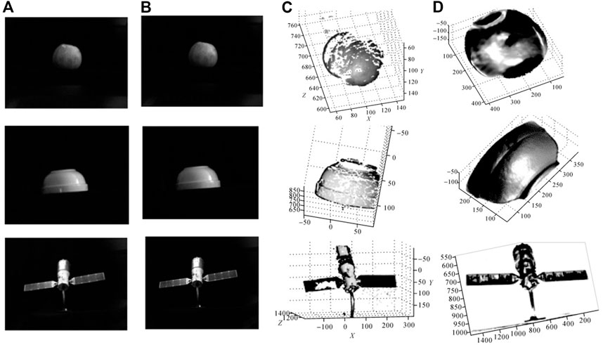
FIGURE 6. Surface reconstruction of the objects. Reproduced under CC-BY-4.0- [39] -http://xb.chinasmp.com/CN/10.11947/j.AGCS.2018.20170624. (A) Intensity images. (B) Results after removing the highlight. (C) Reconstruction results by stereo vision. (D) Reconstruction results by multi-spectral polarization.
In the study of polarization 3D imaging based on specular reflection light, the above-mentioned solutions to the ambiguity zenith angle problem have been introduced. After the accurate normal zenith angle θ is obtained, the last “obstacle” to realizing polarization 3D imaging based on specular reflection is to eliminate the ambiguity of the normal azimuth angle φ. In the early period of polarization 3D imaging, utilizing the ranking technique was the main method to solve the azimuthal ambiguity problem. This method determines the azimuth angle direction by assuming that the surface normal vector at the target boundary is perpendicular to the points at the boundary and there is no obvious “mutation” region on the target surface. Then, it eliminates surface azimuthal ambiguity by propagating the azimuth angle determined at the boundary to the interior of the target surface [31]. Later, Atkinson et al. conducted a related study on the ranking technique [30], but this method has weak applicability in complex target surfaces, and it requires high accuracy for the propagation algorithm, increasing the complexity of the polarization 3D imaging algorithm. Therefore, researchers have started to eliminate azimuthal angle ambiguity by changing the illumination conditions and combining priori information. Two representative types of azimuthal ambiguity elimination techniques are reviewed below.
French scientists Morel et al. [41–43] proposed a method using active illumination to eliminate the ambiguity of azimuth angle. They constructed hemispherical diffuse dome light consisting of four mutual symmetric 1/8 spherical subsystems, as shown in Figure 7A. The system independently controlled four sub-sources to illuminate the target from different directions (east, south, west, and north) for four target hemisphere images, as shown in Figure 7B. The binary image Ibin1 that distinguishes between east and west directions was achieved by comparing the intensity images after illumination from the east and west directions. Similarly, the binary image Ibin2, which can distinguish between south and north directions, was obtained. The detailed procedures for solving the azimuthal ambiguity problem are: 1) φ (azimuthal angle) = ϕ (polarization angle) - π/2; 2) Iquad = 2Ibin1 + Ibin2; 3) If [(Iquad = 0) ∧ (ϕ ≤ 0)] ∨ (Iquad = 1) ∨ (Iquad = 3) ∧ (ϕ ≥ 0), φ = ϕ + π.
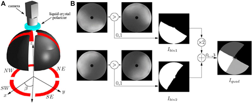
FIGURE 7. (A) The experimental diagram. (B) The acquisition principle of the segmented image. (A,B) Reproduced from [43], with permission from IEEE.
However, in actual operations, the method requires multiple LED light sources and needs to regulate the light sources in different directions separately to solve the ambiguity of the azimuth angle, so it is complex and cannot be applied to moving targets. Meanwhile, it is difficult to implement in outdoor scenes.
In 2017 Cui et al. [33] provided a multi-view polarization 3D imaging technique for reconstructing smooth target surfaces and successfully realized complex target surface 3D reconstruction based on the study of the target local reflectivity. They obtained target intensity and polarization information from at least three viewpoints by setting up multiple polarization cameras at different spatial locations and recovered the camera position as well as an initial 3D shape through the methods of classical motion structure [54] and multi-view stereo [47, 55]. Then, the ambiguity zenith angle of complex object surfaces in high-frequency regions could be corrected by the acquired priori initial 3D shape information, as shown in Figure 8A. Additionally, drawing on the iso-depth contour tracking method [59] in photometric stereo, Cui et al. spreaded the azimuth angle information obtained from the recovery of high-frequency regions to low-frequency regions to eliminate the ambiguity azimuth angle in low-frequency regions. They compared the results with those of some other polarization 3D imaging methods [50, 57], as shown in Figure 8B, which illustrated the accuracy of the proposed method and the 3D imaging feasibility of target surfaces with different reflectivity. However, this method requires several standard points with reliable depth as the “seed” for depth propagation in the tracking process, so it cannot effectively eliminate the ambiguous azimuth angle problem when the feature of the target surface is not sufficient to provide multiple reliable depth reference points. Besides, the method cannot be applied to transparent objects for 3D reconstruction at present.
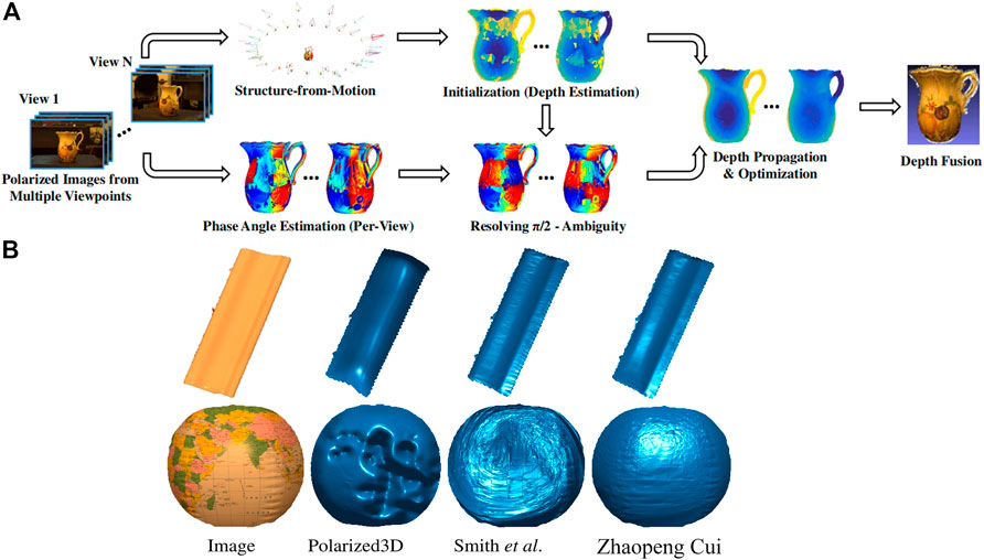
FIGURE 8. (A) The flowchart of the polarimetric multi-view stereo algorithm. (B) Comparison of depth estimation results of Cui [33], Polarized3D [57], and Smith [58]. (A,B) Reproduced from [33], with permission from IEEE.
In the same year, Miyazaki et al. [44] also proposed a polarization 3D imaging technique based on the multi-view stereo to achieve 3D contours of black specular targets. They combined polarization 3D imaging with the space-carving technique. The corresponding points of each view angle image calculated from the camera pose obtained by camera calibration and the 3D shape obtained by spatial sculpting were exploited to analyze the phase angles at the same surface point. In this way, they acquired the surface normal of the entire object surface using the azimuth angle obtained from multiple viewpoints. The addition of polarization information compensates for the defects of the space carving technique in the 3D reconstruction such as the lack of detail texture.
Polarized 3D imaging based on specular reflection is sensitive to the direction of the light source when reconstructing metallic and transparent objects. However, it is not ideal for information extraction and 3D reconstruction of most targets in nature and needs to solve the zenith angle ambiguity problem. With the research and development in the field of materials science and new detectors, the ability to detect and analyze polarization information is improved, especially for the weak polarization properties in the optical field [60–62]. Therefore, an increasing number of researchers focus on the study of polarization 3D imaging based on diffuse reflection and have proposed many classical solutions to the azimuthal ambiguity problem.
Atkinson et al. [45] developed a SfP technique based on diffuse reflection light in 2007. They used photometric stereo vision with the illumination of multiple light sources to eliminate the azimuthal ambiguity in polarization 3D imaging, and their imaging system is shown in Figure 9A. They set up three light sources with fixed positions to collect target intensity images under different illumination conditions as shown in Figure 9A1 and then achieved the elimination of the ambiguity azimuth angle problem by comparing changes in light source intensity information received from different directions on different target areas. Figure 9A2 shows the schematic diagram of the imaging system and the unique azimuth angle value is determined as follows:
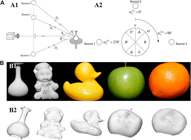
FIGURE 9. (A) The schematic diagram of the imaging system. Adapted from [45], with permission from Springer Nature. (A1) The geometric relationship of the imaging system. (A2) The view of a spherical target from the camera viewpoint. (B) Surface reconstruction of the objects. Adapted from [45], with permission from Springer Nature. (B1) The raw images of the test targets. (B2) The depth estimation of the targets.
The reconstruction results of the method are presented in Figure 9B, which demonstrates that the 3D reconstruction of contour information can be achieved for targets with different surface materials. However, this technique is sensitive to the angle between multiple active light sources and the distance between the light sources and the target, which cannot be implemented easily in actual experiments. Meanwhile, the reconstructed 3D contours are smoother than the ground truth due to the unknown roughness, mutual reflection, and refractive index.
In 2013, Mahmoud et al. [46] proposed a 3D imaging method that combines the polarization 3D imaging technique with the shape from shading (SFS) method. The 3D reconstruction results based on the SFS were exploited as priori deep information to solve the ambiguity problem of the azimuth angle in polarization 3D imaging technology. Since Mahmoud’s polarization 3D imaging technique requires only one view and one imaging band, it is simple to operate, and the equipment required for imaging is easy to set up. The 3D imaging results of the technique are shown in Figure 10A. However, due to the application of the SFS, this technique assumes that the targets are all ideal Lambertian objects, resulting in limited applicable targets and sensitivity to stray light.
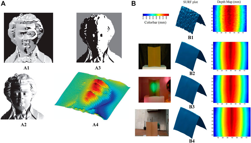
FIGURE 10. (A) Experimental results. Adapted from [46], with permission from IEEE. (A1) Polarization angle. (A2) Diffuse polarization degree. (A3) Intensity image. (A4) Reconstructed surface. (B) Polarization 3D imaging in various lighting conditions. Adapted from [47], with permission from Springer Nature. (B1) TOF Kinect. (B2) Polarization enhancement indoors. (B3) Polarization enhancement under disco lighting. (B4) Polarization enhancement outdoors on a partly sunny.
Kadambi et al. [47] proposed a method to fuse the depth map obtained by Kinect with polarization 3D imaging in 2017. Compared with polarization 3D imaging technology-based photometric stereo vision and SFS, this method avoided the estimation and assumption of scene information such as light sources and targets, and it extended the lighting conditions from special light sources to natural light, realizing high-precision polarization 3D reconstruction. The experimental setup included a Kinect, a normal SLR, and a linear polarizer. The “rough depth map” of the object surface with real depth information was obtained from Kinect, but due to the low resolution of Kinect, the details of the target surface could not be effectively recovered when reconstructing the 3D contour of the target. Therefore, Kadambi combined polarization 3D imaging results containing huge texture details of the target surface with the “rough depth map” to achieve high-precision 3D imaging in various scenes. The 3D imaging results and accuracy analysis for different scenes are shown in Figure 10B. However, due to the limitation of Kinect’s effective detection distance, the polarization 3D imaging technique for depth map fusion cannot perform high-precision 3D imaging of targets at a long distance. Besides, as the “coarse depth map” is not consistent with the polarization 3D imaging in resolution and field of view, complex image processing techniques such as image scaling and registration are required in the actual reconstruction process.
Many polarization 3D imaging techniques fused with other imaging techniques have also been developed [48, 49, 63, 64], such as two excellent methods that have been proposed recently. Tian et al. [48] investigated a novel 3D reconstruction method based on the fusion of SfP and binocular stereo vision. They corrected the azimuth angle errors based on binocular depth; then, they proposed a joint 3D reconstruction model for depth fusion, including a data fitting term and a robust low-rank matrix factorization constraint, to achieve high-quality 3D reconstruction. A series of experiments on different types of objects were conducted to verify the efficiency of the proposed method in comparison with state-of-the-art methods. The reconstruction results presented in Figure 11A indicated that the proposed method can generate accurate 3D reconstruction results with fine texture details. However, it should be noted that due to the combination of binocular stereo vision, the increase of cameras, image scaling, and registration are unavoidable, increasing the cost and complexity of the imaging system. Liu et al. [49] proposed a 3D reconstruction method based on the fusion of SfP and polarization-modulated ranging (PMR), in which only a single image sensor was used to obtain both polarization images and depth data, thus avoiding the image registration problem. Since PMR can provide coarse but accurate and absolute depths and SfP can retrieve inaccurate 3D contours of objects with fine textures, they proposed two fusion models: a joint azimuth estimation model to obtain a fused azimuth angle with π-ambiguity corrected, and a joint zenith estimation model to estimate an accurate fused zenith angle, thus achieving high-quality reconstruction. The specific 3D imaging results are shown in Figure 11B. However, this technique needs further improvement in two aspects: 1) PMR requires active illumination, which makes the proposed technique difficult to be applied outdoors. 2) multiple images are required (three or more polarized images for SfP and two polarization-modulated images for PMR) and the light source needs to be switched.
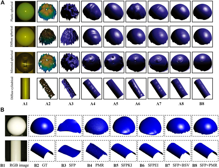
FIGURE 11. (A) Comparison of 3D reconstruction results on regular objects. Adapted from [48], with permission from Elsevier. (A1) RGB image. (A2) Binocular depth. (A3) MC [65]. (A4) DES [, 63, 57]. (A5) DRLPR [30]. (A6) SP [46]. (A7) SFPIK [58]. (A8) SFPIE [67]. (A9) Tian’s method [48]. (B) Comparison of 3D reconstruction results on standard geometric targets. Adapted from [49], with permission from Elsevier. (B1) RGB image. (B2) GT. (B3) SFP. (B4) PMR [68]. (B5) SFPKI [58]. (B6) SFPEI [67]. (B7) SFP + BSV [48]. (B8) Liu’s method [49].
To overcome the limitations of scenes and objects in the polarization 3D imaging technology based on specular reflection or diffuse reflection, researchers have investigated polarization 3D imaging techniques that can be applied to complex scenes and objects. Recently, the rapid proliferation of deep learning, which has successful applications in other fields of 3D imaging [69–73], brings the possibility of breaking through the limitations in traditional polarization 3D imaging techniques. An increasing number of researchers have focused on solving the azimuthal ambiguity problem for complex targets in polarimetric 3D imaging through deep learning [51, 52, 74, 75]. Some successful polarization 3D imaging techniques combined with deep learning are outlined below.
Deschaintre et al. [75] combined polarization imaging with deep learning to achieve a high-quality estimate of 3D object shapes under frontal unpolarized flash illumination. To avoid the correction of ambiguity normal vectors, they used single-view polarization imaging to directly obtain surface normal vectors, depth, and other information like diffuse albedo, roughness, and specular albedo through an encoder-decoder architecture shown in Figure 12A. They trained their network on 512 × 512 images by using two losses: an L1 loss to regularize the training, compute an absolute difference between the output maps and the targets, and a novel polarized rendering loss. Figure 12B presents the comparison of reconstruction results with those of Li et al. [76]. It demonstrates that the technique can recover global 3D contours and other information about the object well. However, at present, the method can only be applied to flash illumination dielectric objects, and the utilization of flash illumination will bring a few specular highlights.
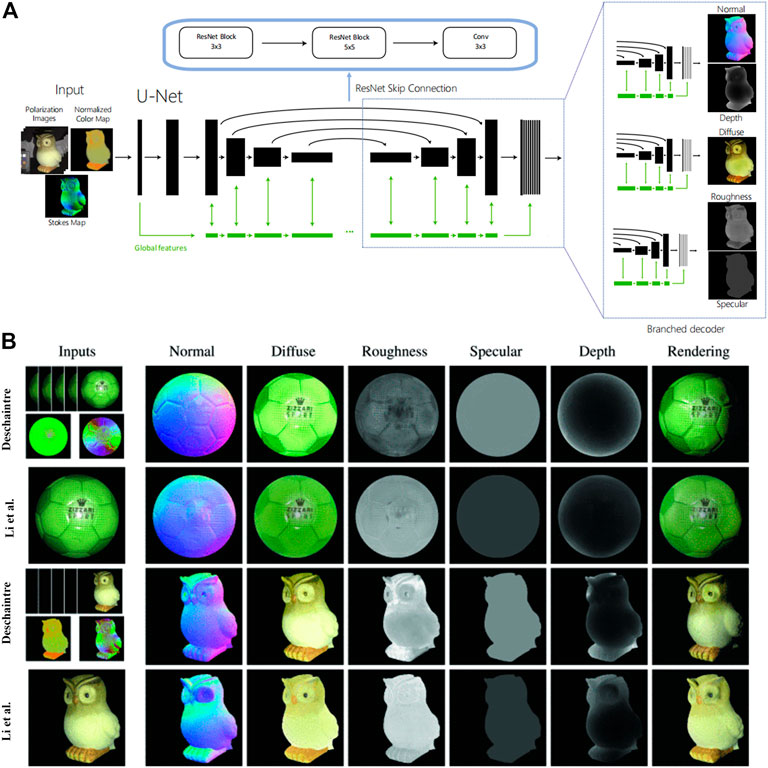
FIGURE 12. (A) Deschaintre’s network architecture based on a general U-Net. (B) A comparison of Deschaintre’s results and the results of Li et al. [76] on real objects. (A,B) Adapted from [75], with permission from IEEE.
Lei et al. [51] applied polarization 3D imaging to complex scenes in the wild. They provided the first real-world scene-level SfP dataset with paired input polarization images and ground-truth normal maps to address the issue of lacking real-world SfP data in complex scenes. In addition to the application of multi-headed self-attentive convolutional neural networks (CNNs) for SfP, per-pixel viewing encoding was also applied to the neural network to handle non-orthographic projection for scene-level SfP. Then, they trained their network on 512 × 512 images by using a cosine similarity loss [50], and the reconstruction results are illustrated in Figure 13A, which reveals that this approach produces accurate surface normal maps. However, the datasets in this technique need to be collected and trained complicatedly, and they are only applicable to specific scenarios.
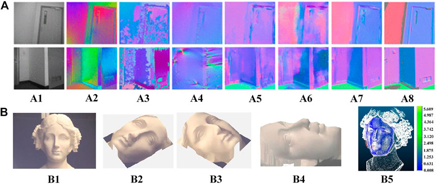
FIGURE 13. (A) Qualitative comparison between Lei’s approach and other polarization methods. Reproduced from [51], with permission from IEEE. (A1) Unpolarized image input. (A2) polarization angle input. (A3) Miyazaki [77]. (A4) Smith [67]. (A5) DeepSfP [50]. (A6) Kondo [78]. (A7) Lei [51]. (A8) ground truth. (B) Reconstructed 3D faces using CNN-based 3DMM. Reproduced under CC-BY-4.0- [52] -https://www.mdpi.com/2304-6732/9/12/924. (B1) A plaster statue with indoor lighting. (B2-B4) three different views of the recovered 3D face of (B1). (B5) point cloud comparison between the laser scanner and Shao’s method.
Shao et al. [52] proposed a learning-based method for passive 3D polarization face reconstruction. The method uses a CNN-based 3D morphable model (3DMM) to generate a rough depth map of the face from the directly captured polarization image. Then, the ambiguity surface normal obtained from polarization can be eliminated from the rough depth map. The construction results of the proposed method in both indoor and outdoor scenarios are shown in Figure 13B. Although the 3D faces are well reconstructed, the dataset requirements still exist in this technique.
The above-mentioned techniques are solutions to the major challenge (the ambiguity problem of normal vectors) in polarimetric 3D imaging. However, many other factors still affect the reconstruction accuracy throughout the polarization 3D imaging process.
To solve the problem of reconstruction distortion in polarization 3D imaging for non-uniform reflective targets, Li et al. [79] presented a near-infrared (NIR) monocular 3D computational polarization imaging method. They addressed the issue of varying intensity between the color patches due to the nonuniform reflectance of the colored target by using the reflected light feature in the near-infrared band. A normalized model of the near-infrared intensity gradient field was established in the non-uniform reflectivity region under monocular to solve the azimuthal ambiguity problem in polarization 3D imaging, and the reconstruction results are shown in Figure 14A.
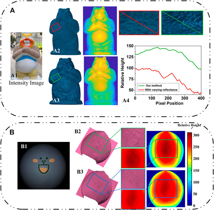
FIGURE 14. (A) Li’s 3D reconstruction results of a colored cartoon plaster target. Reproduced under CC-BY-4.0- [79] - https://opg.optica.org/oe/fulltext.cfm?uri=oe-29-10-15616&id=450808. (A1) Intensity image. (A2) 3D-recovered result without correction for the reflectance. (A3) 3D-recovered result with varying reflectance. (A4) the height variations in the pixels of (A2) and(A3). (B) Experimental results of Cai et al. Reproduced under CC-BY-4.0- [80] - https://opg.optica.org/ao/fulltext.cfm?uri=ao-61-21-6228&id=479184. (B1) The RGB polarization sub-image captured at a direction of 0°. (B2) and (B3) ultimate results of proposed polarization 3D imaging without and with color removal theory, respectively.
Similar to Li’s work, Cai et al. [80] also proposed a novel polarization 3D imaging technique to restore the 3D contours of multi-colored Lambertian objects, but the difference was that they adopted the chromaticity-based color removal theory. Based on the recovered intrinsic intensity, they solved the azimuthal ambiguity problem in a similar approach to achieve high-precision 3D reconstruction, and the results are shown in Figure 14B.
In addition to the influence of color, there are other interference factors in polarization 3D imaging. However, due to the page constraint, other problems and solutions will be briefly introduced as follows.
• Mixture of specular reflection and diffuse reflection
Since the polarization 3D imaging technology is developed based on the polarization characteristics of the reflected light for 3D reconstruction, the accuracy of polarization acquisition is the primary factor affecting the reconstruction accuracy. The mixture of specular and diffuse reflections is the most common challenge affecting polarization accuracy. Umeyama et al. [81] addressed the issue of inaccurate interpretation of polarization field information caused by the mixture of specular and diffuse reflected light. They proposed to exploit the difference of polarization intensity between specular reflection and diffuse reflection to analyze polariton images in different directions through independent component analysis for separating the diffuse and specular components of surface reflection. Shen et al. [82] proposed a method to separate diffuse and specular reflection components from a single image. They constructed a pseudo-chromatic space to classify image pixels and achieved fast and accurate specular reflection light removal without any local operation on the specular reflection information. Wang et al. [83] presented a global energy minimization specular reflection light removal method based on polarization characteristics to eliminate color distortions based on color intensity information for separating specular reflection from diffuse reflection and reducing the error in the interpretation of polarization information. Li et al. [84] derived an analytical expression of diffuse reflection light under mixed optical fields and proposed a method to remove specular reflection light based on the analysis of the intensity and polarization field distribution characteristics, thus accurately interpreting polarization information.
• Gradient field integration
Gradient field integration directly affects the accuracy of reconstructing results, and it is another essential process of reconstructing the surface from the obtained normal vector of micro-plane elements. The Frankot-Chellappa method [85] is commonly used in the SfP method, but it takes the finite center difference as the differentiation operator, which has a large truncation error and does not constrain adjacent heights, to establish the difference-slope relationship, increasing reconstruction errors. To improve the integration accuracy, Ren et al. [86] proposed an improved higher-order finite-difference least-squares product method for circular regions and incomplete gradient data, which can handle incomplete gradient data more directly and efficiently. Qiao et al. [87] formulated Fourier-based exact integration square break error to increase the height and slope of the operator for obtaining higher 3D reconstruction accuracy. Smith et al. [88] presented an integration method for segmental fitting of gradient data using spline curves, which can obtain accurate integration results at surface boundaries.
• Absolute depth recovery
According to the analysis in Section 2, the depth information reconstructed by polarization 3D imaging is the result of integrating normal vectors of all pixel points, so it is the relative depth display in the pixel coordinate system. To recover the absolute depth of the 3D contour based on the polarization characteristics, Ping et al. [89] combined conventional polarization 3D imaging with binocular stereo vision. They calculated the coordinate transformation parameters between the image pixel coordinate system and the world coordinate system with the camera parameters obtained from binocular stereo calibration; then, the relative depth in the pixel coordinate system acquired by polarization was converted to the absolute depth in the world coordinate system by using the least-squares method. Some other methods [48, 49, 64] can also recover the absolute depth of the object 3D contour obtained from SfP.
Although the polarization 3D imaging technology has been further developed and many SfP techniques have been proposed, its application to engineering, medical, industrial, and daily life fields is still a challenge. This section lists some challenging issues worth exploring to further advance the field of polarization 3D imaging.
As introduced in Section 3, many SfP techniques have been proposed, but there are many limitations in these techniques, preventing widespread commercial applications of the polarization 3D imaging technology. More challenges need to be overcome: 1) How to perform high-precision polarization 3D reconstruction under monocular conditions without the assistance of other detection methods? 2) Is it possible to realize real-time polarization 3D imaging? 3) How to apply SfP to more complex objects and scenes like multiple discrete objects? 4) How to solve the polarization dataset acquisition problem in deep learning? 5) How to improve polarization detection accuracy in visible, infrared, and other wavelengths? The above-mentioned problems are important research directions of future polarization 3D imaging technology, and some difficult points need to be addressed in practical applications of polarization 3D imaging.
The record and storage follow the information acquisition process. However, the sizes of conventional 3D image files represented by OBJ, PLY, and STL are often one order of magnitude larger than those of 2D files represented by JPG, BMP, and TIF. How can one effectively store and deliver such a huge amount of 3D data is a key issue to applying polarization 3D imaging technology in practice. Although some efforts [90–94] have been made to compress 3D range data, none of these methods is proposed for efficient 3D data storage.
Traditionally, the polarization characteristics of reflected light are obtained by rotating a polarizer placed in front of the camera, which is difficult to promote practically. Although some manufacturers like Sony has manufactured integrated devices such as polarization chips, the chips have shortcomings of weak extinction ratio, low resolution [95–97], etc. The integration of hardware facilities has gradually failed to keep up with the development of polarization 3D imaging technology. Therefore, efforts to promote hardware integration of polarization 3D imaging systems are highly needed to advance polarization 3D imaging technology.
The value of practical applications is a huge motivation for technological progress. However, though many SfP techniques have been developed, none of the existing techniques are effectively applied in practice. So far, many other 3D imaging techniques have been applied to practical fields. Binocular stereo vision is commonly used in fields of robotic vision [98–100]. Deep learning and lidar 3D imaging are widely used in autonomous driving recently [101–105]. Structured light 3D imaging technology is mostly used in the detection of defects in precision industrial products because of its high accuracy [106–108]. Therefore, the specific application fields of polarization 3D imaging technology should be selected according to its technical advantages. For example, considering the long-distance detection advantage of polarization 3D imaging technology, 3D mapping of remote sensing may become a significant application field.
This paper presents a comprehensive and detailed review of the polarization 3D imaging mechanism and some classical SfP techniques. Especially, this paper focuses on the problems and solutions of normal ambiguity in polarization 3D imaging technology by explaining technical fundamentals, demonstrating experimental results, and analyzing capabilities/limitations. Besides, other problems and related techniques in polarization 3D imaging are also introduced. Finally, our perspectives on some remained challenges in polarization 3D imaging technology are summarized to inspire the readers.
XL, ZL, and YC prepared the references and data. JW was involved in the conception and design of the project. XL wrote the manuscript with input from all authors. XS reviewed and improved the writing. CP and JS supervised the project. All authors contributed to the manuscript revision, read, and approved the submitted version.
National Natural Science Foundation of China (NSFC) (62205256); China Postdoctoral Science Foundation (2022TQ0246); CAS Key Laboratory of Space Precision Measurement Technology (SPMT2023-02).
The authors declare that the research was conducted in the absence of any commercial or financial relationships that could be construed as a potential conflict of interest.
All claims expressed in this article are solely those of the authors and do not necessarily represent those of their affiliated organizations, or those of the publisher, the editors and the reviewers. Any product that may be evaluated in this article, or claim that may be made by its manufacturer, is not guaranteed or endorsed by the publisher.
1. Sonka M, Hlavac V, Boyle R. Image processing, analysis, and machine vision. Boston, MA: Cengage Learning (2014).
2. Shao X-P, Liu F, Li W, Yang L, Yang S, Liu J. Latest progress in computational imaging technology and application. Laser Optoelectronics Prog (2020) 57(2):020001. doi:10.3788/lop57.020001
3. Shechtman Y, Eldar YC, Cohen O, Chapman HN, Miao J, Segev M. Phase retrieval with application to optical imaging: A contemporary Overview. IEEE Signal Processing Magazine (2015) 32(3):87–109. doi:10.1109/MSP.2014.2352673
4. Rybka T, Ludwig M, Schmalz MF, Knittel V, Brida D, Leitenstorfer A. Sub-cycle optical phase control of nanotunnelling in the single-electron regime. Nat Photon (2016) 10(10):667–70. doi:10.1038/nphoton.2016.174
5. Chen C, Gao L, Gao W, Ge C, Du X, Li Z, et al. Circularly polarized light detection using chiral hybrid perovskite. Nat Commun (2019) 10(1):1927. doi:10.1038/s41467-019-09942-z
6. Wang X, Cui Y, Li T, Lei M, Li J, Wei Z. Recent advances in the functional 2d photonic and optoelectronic devices. Adv Opt Mater (2019) 7(3):1801274. doi:10.1002/adom.201801274
7. Tahara T, Quan X, Otani R, Takaki Y, Matoba O. Digital holography and its multidimensional imaging applications: A review. Microscopy (2018) 67(2):55–67. doi:10.1093/jmicro/dfy007
8. Clark RA, Mentiplay BF, Hough E, Pua YH. Three-dimensional cameras and skeleton pose tracking for physical function assessment: A review of uses, validity, current developments and Kinect alternatives. Gait & posture (2019) 68:193–200. doi:10.1016/j.gaitpost.2018.11.029
9. Zhou S, Xiao S. 3d face recognition: A survey. Human-centric Comput Inf Sci (2018) 8(1):35–27. doi:10.1186/s13673-018-0157-2
10. Adjabi I, Ouahabi A, Benzaoui A, Taleb-Ahmed A. Past, present, and future of face recognition: A review. Electronics (2020) 9(8):1188. doi:10.3390/electronics9081188
11. Ben Abdallah H, Jovančević I, Orteu J-J, Brèthes L. Automatic inspection of aeronautical mechanical assemblies by matching the 3d cad model and real 2d images. J Imaging (2019) 5(10):81. doi:10.3390/jimaging5100081
12. Qian J, Feng S, Xu M, Tao T, Shang Y, Chen Q, et al. High-resolution real-time 360∘ 3d surface defect inspection with fringe projection profilometry. Opt Lasers Eng (2021) 137:106382. doi:10.1016/j.optlaseng.2020.106382
13. Pham QH, Sevestre P, Pahwa RS, Zhan H, Pang CH, Chen Y, et al. A 3d dataset: Towards autonomous driving in challenging environments. In: Proceeding of the 2020 IEEE International Conference on Robotics and Automation (ICRA); May 2020; Paris, France. IEEE (2020).
14. Li P, Zhao H, Liu P, Cao F. Rtm3d: Real-Time monocular 3d detection from object keypoints for autonomous driving. In: Computer Vision–ECCV 2020: 16th European Conference; August 23–28, 2020; Glasgow, UK. Springer (2020). Proceedings, Part III 16.
15. Xue Y, Cheng T, Xu X, Gao Z, Li Q, Liu X, et al. High-accuracy and real-time 3d positioning, tracking system for medical imaging applications based on 3d digital image correlation. Opt Lasers Eng (2017) 88:82–90. doi:10.1016/j.optlaseng.2016.07.002
16. Pan Z, Huang S, Su Y, Qiao M, Zhang Q. Strain field measurements over 3000 C using 3d-digital image correlation. Opt Lasers Eng (2020) 127:105942. doi:10.1016/j.optlaseng.2019.105942
17. Chen F, Brown GM, Song M. Overview of 3-D shape measurement using optical methods. Opt Eng (2000) 39(1):10–22. doi:10.1117/1.602438
18. Fang Y, Wang X, Sun Z, Zhang K, Su B. Study of the depth accuracy and entropy characteristics of a tof camera with coupled noise. Opt Lasers Eng (2020) 128:106001. doi:10.1016/j.optlaseng.2020.106001
19. Liu B, Yu Y, Jiang S. Review of advances in lidar detection and 3d imaging. Opto-Electronic Eng (2019) 46(7):190167. doi:10.12086/oee.2019.190167
20. Zuo C, Feng S, Huang L, Tao T, Yin W, Chen Q. Phase shifting algorithms for fringe projection profilometry: A review. Opt lasers Eng (2018) 109:23–59. doi:10.1016/j.optlaseng.2018.04.019
21. Zhu Z, Li M, Zhou F, You D. Stable 3d measurement method for high dynamic range surfaces based on fringe projection profilometry. Opt Lasers Eng (2023) 166:107542. doi:10.1016/j.optlaseng.2023.107542
22. Tippetts B, Lee DJ, Lillywhite K, Archibald J. Review of stereo vision algorithms and their suitability for resource-limited systems. J Real-Time Image Process (2016) 11:5–25. doi:10.1007/s11554-012-0313-2
23. Shi S, Ding J, New TH, Soria J. Light-field camera-based 3d volumetric particle image velocimetry with dense ray tracing reconstruction technique. Experiments in Fluids (2017) 58:78–16. doi:10.1007/s00348-017-2365-3
24. Koshikawa K. A polarimetric approach to shape understanding of glossy objects. Adv Robotics (1979) 2(2):190.
25. Wallace AM, Liang B, Trucco E, Clark J. Improving depth image acquisition using polarized light. Int J Comp Vis (1999) 32(2):87–109. doi:10.1023/A:1008154415349
26. Saito M, Sato Y, Ikeuchi K, Kashiwagi H. Measurement of surface orientations of transparent objects by use of polarization in highlight. JOSA A (1999) 16(9):2286–93. doi:10.1364/JOSAA.16.002286
27. Müller V. Elimination of specular surface-reflectance using polarized and unpolarized light. In: Proceeding of the Computer Vision—ECCV'96: 4th European Conference on Computer Vision Cambridge; April 15–18, 1996; UK. Springer (1996). Proceedings Volume II 4.
28. Wolff LB, Boult TE. Constraining object features using a polarization reflectance model. Phys Based Vis Princ Pract Radiom (1993) 1:167.
29. Sato Y, Wheeler Ikeuchi, MD K. Object shape and reflectance modeling from observation. Proceedings of the 24th annual conference on Computer graphics and interactive techniques; 1997.
30. Atkinson GA, ER Hancock, . Recovery of surface orientation from diffuse polarization. IEEE Trans image Process (2006) 15(6):1653–64. doi:10.1109/TIP.2006.871114
31. Miyazaki, , Kagesawa, , Ikeuchi , Polarization-based transparent surface modeling from two views. Proceedings Ninth IEEE International Conference on Computer Vision (2003) 2: 1381–1386. doi:10.1109/ICCV.2003.1238651
32. Bass M. Handbook of Optics: Volume I-geometrical and physical Optics, polarized light, components and instruments. McGraw-Hill Education (2010).
33. Cui Z, Gu J, Shi B, Tan P, Kautz J. Polarimetric multi-view stereo. In: Proceedings of the IEEE conference on computer vision and pattern recognition; July 2017; Honolulu, HI, USA. IEEE (2017).
34. Li X, Liu F, Shao X-P. Research progress on polarization 3d imaging technology. J Infrared Millimeter Waves (2021) 40(2):248–62.
35. Monteiro M, Stari C, Cabeza C, Martí AC. The polarization of light and Malus’ law using smartphones. Phys Teach (2017) 55(5):264–6. doi:10.1119/1.4981030
36.Partridge, M, and Saull, R editors. Three-dimensional surface reconstruction using emission polarization. Image and signal processing for remote sensing II. Paris, France: SPIE (1995).
37. Miyazaki D, Saito M, Sato Y, Ikeuchi K. Determining surface orientations of transparent objects based on polarization degrees in visible and infrared wavelengths. JOSA A (2002) 19(4):687–94. doi:10.1364/JOSAA.19.000687
38. Stolz C, Ferraton M, Meriaudeau F. Shape from polarization: A method for solving zenithal angle ambiguity. Opt Lett (2012) 37(20):4218–20. doi:10.1364/OL.37.004218
39. Jinglei H, Yongqiang Z, Haimeng Z, Brezany P, Jiayu S. 3d reconstruction of high-reflective and textureless targets based on multispectral polarization and machine vision. Acta Geodaetica et Cartographica Sinica (2018) 47(6):816. doi:10.11947/j.AGCS.2018.20170624
40. Zhao Y, Yi C, Kong SG, Pan Q, Cheng Y, Zhao Y, et al. Multi-band polarization imaging. Springer (2016).
41.Morel, O, Meriaudeau, F, Stolz, C, and Gorria, P, editors. Polarization imaging applied to 3d reconstruction of specular metallic surfaces. Machine vision applications in industrial inspection XIII. San Jose, CA: SPIE (2005).
42. Morel O, Stolz C, Meriaudeau F, Gorria P. Active lighting applied to three-dimensional reconstruction of specular metallic surfaces by polarization imaging. Appl Opt (2006) 45(17):4062–8. doi:10.1364/AO.45.004062
43. Morel O, Ferraton M, Stolz C, Gorria P. Active lighting applied to shape from polarization. In: Proceeding of the 2006 International Conference on Image Processing; October 2006; Atlanta, GA, USA. IEEE (2006).
44. Miyazaki D, Shigetomi T, Baba M, Furukawa R, Hiura S, Asada N. Surface normal estimation of black specular objects from multiview polarization images. Opt Eng (2017) 56(4):041303. doi:10.1117/1.OE.56.4.041303
45. Atkinson GA, Hancock ER. Surface reconstruction using polarization and photometric stereo. In: Computer Analysis of Images and Patterns: 12th International Conference, CAIP 2007; August 27-29, 2007; Vienna, Austria, 12. Springer (2007).
46. Mahmoud AH, El-Melegy MT, Farag AA. Direct method for shape recovery from polarization and shading. In: Proceeding of the 2012 19th IEEE International Conference on Image Processing; September 2012; Orlando, FL, USA. IEEE (2012).
47. Kadambi A, Taamazyan V, Shi B, Raskar R. Depth sensing using geometrically constrained polarization normals. Int J Comp Vis (2017) 125:34–51. doi:10.1007/s11263-017-1025-7
48. Tian X, Liu R, Wang Z, Ma J. High quality 3d reconstruction based on fusion of polarization imaging and binocular stereo vision. Inf Fusion (2022) 77:19–28. doi:10.1016/j.inffus.2021.07.002
49. Liu R, Liang H, Wang Z, Ma J, Tian X. Fusion-based high-quality polarization 3d reconstruction. Opt Lasers Eng (2023) 162:107397. doi:10.1016/j.optlaseng.2022.107397
50. Ba Y, Gilbert A, Wang F, Yang J, Chen R, Wang Y, et al. Deep shape from polarization. In: Proceeding of the Computer Vision–ECCV 2020: 16th European Conference; August 23–28, 2020; Glasgow, UK. Springer (2020).Proceedings, Part XXIV 16
51. Lei C, Qi C, Xie J, Fan N, Koltun V, Chen V. Shape from polarization for complex scenes in the wild. In: Proceedings of the IEEE/CVF Conference on Computer Vision and Pattern Recognition. IEEE (2022).
52.Han, P, Li, X, Liu, F, Cai, Y, Yang, K, Yan, Met al. Accurate passive 3d polarization face reconstruction under complex conditions assisted with deep learning. Photonics. Basel, Switzerland: Multidisciplinary Digital Publishing Institute (2022).
53. Born M, Wolf E. principles of Optics, 7th (expanded) edition. 461. United Kingdom: Press Syndicate of the University of Cambridge (1999). p. 401–24.
54. Wu C. Towards linear-time incremental structure from motion. In: Proceeding of the 2013 International Conference on 3D Vision-3DV 2013; June 2013; Seattle, WA, USA. IEEE (2013).
55.Fuhrmann, S, Langguth, F, and Goesele, M, editors. Mve-a multi-view reconstruction environment. Eindhoven, Netherlands: GCH (2014).
56. Galliani S, Lasinger K, Schindler K. Massively parallel multiview stereopsis by surface normal diffusion. In: Proceedings of the IEEE International Conference on Computer Vision; December 2015; Santiago, Chile. IEEE (2015).
57. Kadambi A, Taamazyan V, Shi B, Raskar R. Polarized 3d: High-quality depth sensing with polarization cues. In: Proceedings of the IEEE International Conference on Computer Vision. IEEE (2015).
58.Linear depth estimation from an uncalibrated, monocular polarisation image. In: Smith WA, Ramamoorthi R, and Tozza S, editors. Proceedings of the Computer Vision–ECCV 2016: 14th European Conference; October 11-14, 2016; Amsterdam, The Netherlands. Springer (2016). Proceedings, Part VIII 14.
59. Zhou Z, Wu Z, Tan P. Multi-view photometric stereo with spatially varying isotropic materials. In: Proceedings of the IEEE Conference on Computer Vision and Pattern Recognition; June 2013; Portland, OR, USA. IEEE (2013).
60. Wei ZM, Xia JB. Recent progress in polarization-sensitive photodetectors based on low-dimensional semiconductors. Acta Physica Sinica -Chinese Edition (2019) 68(16):163201. doi:10.7498/aps.68.20191002
61. Zhang C, Hu J, Dong Y, Zeng A, Huang H, Wang C. High efficiency all-dielectric pixelated metasurface for near-infrared full-Stokes polarization detection. Photon Res (2021) 9(4):583–9. doi:10.1364/PRJ.415342
62. Shang X, Wan L, Wang L, Gao F, Li H. Emerging materials for circularly polarized light detection. J Mater Chem C (2022) 10(7):2400–10. doi:10.1039/D1TC04163K
63. Shakeri M, Loo SY, Zhang H, Hu K. Polarimetric monocular dense mapping using relative deep depth prior. IEEE Robotics Automation Lett (2021) 6(3):4512–9. doi:10.1109/LRA.2021.3068669
64. Tan Z, Zhao B, Ji Y, Xu X, Kong Z, Liu T, et al. A welding seam positioning method based on polarization 3d reconstruction and linear structured light imaging. Opt Laser Tech (2022) 151:108046. doi:10.1016/j.optlastec.2022.108046
65. Nguyen LT, Kim J, Shim B. Low-rank matrix completion: A contemporary survey. IEEE Access (2019) 7:94215–37. doi:10.1109/ACCESS.2019.2928130
66. Kovesi P. Shapelets correlated with surface normals produce surfaces. In: Proceeding of the Tenth IEEE International Conference on Computer Vision (ICCV'05) Volume 1; October 2005; Beijing, China. IEEE (2005).
67. Smith WA, Ramamoorthi R, Tozza S. Height-from-Polarisation with unknown lighting or albedo. IEEE Trans pattern Anal machine intelligence (2018) 41(12):2875–88. doi:10.1109/TPAMI.2018.2868065
68. Liu R, Tian X, Li S. Polarisation-modulated photon-counting 3d imaging based on a negative parabolic pulse model. Opt Express (2021) 29(13):20577–89. doi:10.1364/OE.427997
69. Poggi M, Tosi F, Batsos K, Mordohai P, Mattoccia S. On the synergies between machine learning and binocular stereo for depth estimation from images: A survey. IEEE Trans Pattern Anal Machine Intelligence (2021) 44(9):5314–34. doi:10.1109/TPAMI.2021.3070917
70. Hu Y, Zhen W, Scherer S. Deep-learning assisted high-resolution binocular stereo depth reconstruction. In: Proceeding of the 2020 IEEE International Conference on Robotics and Automation (ICRA). IEEE (2020).
71. Chen G, Han K, Shi B, Matsushita Y, Wong K-YK. Deep photometric stereo for non-lambertian surfaces. IEEE Trans Pattern Anal Machine Intelligence (2020) 44(1):129–42. doi:10.1109/TPAMI.2020.3005397
72. Van der Jeught S, Dirckx JJ. Deep neural networks for single shot structured light profilometry. Opt express (2019) 27(12):17091–101. doi:10.1364/OE.27.017091
73. Yang G, Wang Y. Three-dimensional measurement of precise shaft parts based on line structured light and deep learning. Measurement (2022) 191:110837. doi:10.1016/j.measurement.2022.110837
74. Zou S, Zuo X, Qian Y, Wang S, Xu C, Gong M, et al. 3d human shape reconstruction from a polarization image. In: Proceeding of the Computer Vision–ECCV 2020: 16th European Conference; August 23–28, 2020; Glasgow, UK. Springer (2020). Proceedings, Part XIV 16.
75. Deschaintre V, Lin Y, Ghosh A. Deep polarization imaging for 3d shape and svbrdf acquisition. In: Proceedings of the IEEE/CVF Conference on Computer Vision and Pattern Recognition. IEEE (2021).
76. Li Z, Xu Z, Ramamoorthi R, Sunkavalli K, Chandraker M. Learning to reconstruct shape and spatially-varying reflectance from a single image. ACM Trans Graphics (Tog) (2018) 37(6):1–11. doi:10.1145/3272127.3275055
77. Miyazaki D, Tan RT, Hara K, Ikeuchi K. Polarization-based inverse rendering from a single view. In: Proceeding of the Computer Vision, IEEE International Conference on; October 2003; Nice, France. IEEE Computer Society (2003).
78. Kondo Y, Ono T, Sun L, Hirasawa Y, Murayama J. Accurate polarimetric brdf for real polarization scene rendering. In: Proceeding of the Computer Vision–ECCV 2020: 16th European Conference; August 23–28, 2020; Glasgow, UK. Springer (2020). Proceedings, Part XIX 16.
79. Li X, Liu F, Han P, Zhang S, Shao X. Near-infrared monocular 3d computational polarization imaging of surfaces exhibiting nonuniform reflectance. Opt Express (2021) 29(10):15616–30. doi:10.1364/OE.423790
80. Cai Y, Liu F, Shao X, Cai G. Impact of color on polarization-based 3d imaging and countermeasures. Appl Opt (2022) 61(21):6228–33. doi:10.1364/AO.462778
81. Umeyama S, Godin G. Separation of diffuse and specular components of surface reflection by use of polarization and statistical analysis of images. IEEE Trans Pattern Anal Machine Intelligence (2004) 26(5):639–47. doi:10.1109/TPAMI.2004.1273960
82. Shen H-L, Zheng Z-H. Real-time highlight removal using intensity ratio. Appl Opt (2013) 52(19):4483–93. doi:10.1364/AO.52.004483
83. Wang F, Ainouz S, Petitjean C, A Bensrhair,. Specularity removal: A global energy minimization approach based on polarization imaging. Computer Vis Image Understanding (2017) 158:31–9. doi:10.1016/j.cviu.2017.03.003
84.Li, X, Liu, F, Cai, Y, Huang, S, Han, P, and Shao, X, editors. Polarization 3d imaging having highlighted areas. Frontiers in Optics. Washington D.C: Optica Publishing Group (2019).
85. Frankot RT, Chellappa R. A method for enforcing integrability in shape from shading algorithms. IEEE Trans pattern Anal machine intelligence (1988) 10(4):439–51. doi:10.1109/34.3909
86. Ren H, Gao F, Jiang X. Improvement of high-order least-squares integration method for stereo deflectometry. Appl Opt (2015) 54(34):10249–55. doi:10.1364/AO.54.010249
87. Sun Z, Qiao Y, Jiang Z, Xu X, Zhou J, Gong X. An accurate fourier-based method for three-dimensional reconstruction of transparent surfaces in the shape-from-polarization method. IEEE Access (2020) 8:42097–110. doi:10.1109/ACCESS.2020.2977097
88. Smith GA. 2d zonal integration with unordered data. Appl Opt (2021) 60(16):4662–7. doi:10.1364/AO.426162
89. Ping XX, Liu Y, Dong XM, Zhao YQ, Zhang-Yan, , University NP. 3-D reconstruction of textureless and high-reflective target by polarization and binocular stereo vision. J Infrared Millimeter Waves (2017). doi:10.11972/j.issn.1001-9014.2017.04.009
90. Karpinsky N, Zhang S. 3d range geometry video compression with the H 264 codec. Opt Lasers Eng (2013) 51(5):620–5. doi:10.1016/j.optlaseng.2012.12.021
91. Wang Y, Zhang L, Yang S, Ji F. Two-Channel high-accuracy holoimage technique for three-dimensional data compression. Opt Lasers Eng (2016) 85:48–52. doi:10.1016/j.optlaseng.2016.04.020
92. Li S, Jiang T, Tian Y, Huang T. 3d human skeleton data compression for action recognition. In: Proceeding of the 2019 IEEE Visual Communications and Image Processing (VCIP); December 2019; Sydney, NSW, Australia. IEEE (2019).
93. Wang J, Ding D, Li Z, Ma Z. Multiscale point cloud geometry compression. In: Proceeding of the 2021 Data Compression Conference (DCC); March 2021; Snowbird, UT, USA. IEEE (2021).
94. Gu S, Hou J, Zeng H, Yuan H, Ma K-K. 3d point cloud attribute compression using geometry-guided sparse representation. IEEE Trans Image Process (2019) 29:796–808. doi:10.1109/TIP.2019.2936738
95. Maruyama Y, Terada T, Yamazaki T, Uesaka Y, Nakamura M, Matoba Y, et al. 3.2-MP Back-Illuminated Polarization Image Sensor with Four-Directional Air-Gap Wire Grid and 2.5-<inline-formula> <tex-math notation=LaTeX>$\mu$ </tex-math> </inline-formula>m Pixels. IEEE Trans Electron Devices (2018) 65:2544–51. doi:10.1109/TED.2018.2829190
96. Ren H, Yang J, Liu X, Huang P, Guo L. Sensor modeling and calibration method based on extinction ratio error for camera-based polarization navigation sensor. Sensors (2020) 20:3779. doi:10.3390/s20133779
97. Lane C, Rode D, Rösgen T. Calibration of a polarization image sensor and investigation of influencing factors. Appl Opt (2022) 61:C37–C45. doi:10.1364/AO.437391
98. Wang C, Zou X, Tang Y, Luo L, Feng W. Localisation of litchi in an unstructured environment using binocular stereo vision. Biosyst Eng (2016) 145:39–51. doi:10.1016/j.biosystemseng.2016.02.004
99. Zhai G, Zhang W, Hu W, Ji Z. Coal mine rescue robots based on binocular vision: A review of the state of the art. IEEE Access (2020) 8:130561–75. doi:10.1109/ACCESS.2020.3009387
100. Kim W-S, Lee D-H, Kim Y-J, Kim T, Lee W-S, Choi C-H. Stereo-vision-based crop height estimation for agricultural robots. Comput Elect Agric (2021) 181:105937. doi:10.1016/j.compag.2020.105937
101. Fujiyoshi H, Hirakawa T, Yamashita T. Deep learning-based image recognition for autonomous driving. IATSS Res (2019) 43(4):244–52. doi:10.1016/j.iatssr.2019.11.008
102. Grigorescu S, Trasnea B, Cocias T, Macesanu G. A survey of deep learning techniques for autonomous driving. J Field Robotics (2020) 37(3):362–86. doi:10.1002/rob.21918
103. Cui Y, Chen R, Chu W, Chen L, Tian D, Li Y, et al. Deep learning for image and point cloud fusion in autonomous driving: A review. IEEE Trans Intell Transportation Syst (2021) 23(2):722–39. doi:10.1109/TITS.2020.3023541
104. Royo S, Ballesta-Garcia M. An Overview of lidar imaging systems for autonomous vehicles. Appl Sci (2019) 9(19):4093. doi:10.3390/app9194093
105. Zhao X, Sun P, Xu Z, Min H, Yu H. Fusion of 3d lidar and camera data for object detection in autonomous vehicle applications. IEEE Sensors J (2020) 20(9):4901–13. doi:10.1109/JSEN.2020.2966034
106. Chu H-H, Wang Z-Y. A vision-based system for post-welding quality measurement and defect detection. Int J Adv Manufacturing Tech (2016) 86:3007–14. doi:10.1007/s00170-015-8334-1
107. Yang L, Li E, Long T, Fan J, Liang Z. A novel 3-D path extraction method for arc welding robot based on stereo structured light sensor. IEEE Sensors J (2018) 19(2):763–73. doi:10.1109/JSEN.2018.2877976
Keywords: polarization 3D imaging, ambiguity normal, single view, passive imaging, depth fusion, deep learning, challenge analysis
Citation: Li X, Liu Z, Cai Y, Pan C, Song J, Wang J and Shao X (2023) Polarization 3D imaging technology: a review. Front. Phys. 11:1198457. doi: 10.3389/fphy.2023.1198457
Received: 01 April 2023; Accepted: 18 April 2023;
Published: 09 May 2023.
Edited by:
Huadan Zheng, Jinan University, ChinaReviewed by:
Dekui Li, Hefei University of Technology, ChinaCopyright © 2023 Li, Liu, Cai, Pan, Song, Wang and Shao. This is an open-access article distributed under the terms of the Creative Commons Attribution License (CC BY). The use, distribution or reproduction in other forums is permitted, provided the original author(s) and the copyright owner(s) are credited and that the original publication in this journal is cited, in accordance with accepted academic practice. No use, distribution or reproduction is permitted which does not comply with these terms.
*Correspondence: Xiaopeng Shao, eHBzaGFvQHhpZGlhbi5lZHUuY24=
Disclaimer: All claims expressed in this article are solely those of the authors and do not necessarily represent those of their affiliated organizations, or those of the publisher, the editors and the reviewers. Any product that may be evaluated in this article or claim that may be made by its manufacturer is not guaranteed or endorsed by the publisher.
Research integrity at Frontiers

Learn more about the work of our research integrity team to safeguard the quality of each article we publish.