
95% of researchers rate our articles as excellent or good
Learn more about the work of our research integrity team to safeguard the quality of each article we publish.
Find out more
ORIGINAL RESEARCH article
Front. Phys. , 18 May 2023
Sec. Optics and Photonics
Volume 11 - 2023 | https://doi.org/10.3389/fphy.2023.1196067
This article is part of the Research Topic Acquisition and Application of Multimodal Sensing Information View all 12 articles
Distributed Acoustic Sensor (DAS) has potential in applications such as hydroacoustic detection. In this paper, a dual-pulse heterodyne distributed acoustic sensor (DAS) system using a semiconductor optical amplifier (SOA)-based fiber ring laser (FRL) is proposed. Unlike the previous DAS system configurations, the SOA-based FRL replaces the narrow linewidth laser (NLL) and pulse modulator, reducing costs and simplifying the system. The system is demonstrated theoretically and validated experimentally. The adaptability of the SOA-based FRL in the heterodyne DAS system has been demonstrated in the experiments. Using the dual-pulse heterodyne detection method, the sensor system responds well to distributed acoustic detection and achieves accurate demodulation and positioning. A high signal-to-noise ratio (SNR) of 42.51 dB at 3 kHz is demonstrated as a demodulation result. The system’s frequency range is 5 Hz to 5 kHz with a spatial resolution of 12 m. The proposed approach shows a broad application prospect for low-cost, large-scale, high-SNR distributed acoustic detection in maritime surveillance.
Marine microseismic/acoustic monitoring is crucial for exploiting marine mineral resources and national underwater military defense [1, 2]. DAS based on phase-sensitive optical time-domain reflectometry (Φ-OTDR) has recently attracted attention in applications such as hydroacoustic detection [3, 4]. Φ-OTDR, a promising technique for DAS, has demonstrated its ability to provide real-time measurement reaching into the acoustic range [5–7]. In particular, Φ-OTDR has attracted increasing interest in hydroacoustic detection research due to its unique performance, including long sensing range, high spatial resolution, and wide dynamic range.
The DAS introduces a phase demodulation part to obtain the phase change caused by external acoustic signals compared to the traditional Φ-OTDR. Thus, several phase demodulation schemes have been developed. Generally, these schemes can be divided into homodyne [8, 9] and heterodyne [10, 11] according to different signaling methods. A heterodyne DAS using dual pulses was proposed. The system can simultaneously detect the actual waveforms of multiple vibration events with a high signal-to-noise ratio (SNR) [11]. Recently, researchers have been focusing on improving the performance of DAS to meet the requirements of practical applications. To accurately perform high-precision vibration identification based on high SNR acoustic signals, the system must have a high SNR level [12, 13]. To improve the SNR, signal processing techniques, such as wavelet denoising [14–18], filtering algorithms [19, 20], and pulse coding methods [21–23], are employed in the system. Aside from approaches based on signal processing, those based on optical techniques used a high-power laser [24, 25], high-performance photodetectors (PDs) [26], or optical amplifiers [27–29].
For interrogation purposes, a narrow linewidth laser (NLL) combined with a pulse modulator is typically used in DAS [30]. The pulse modulator converts the continuous light from the NLL into pulsed light. The non-ideal switching characteristics of the modulator introduce noise into the system, a significant source of the noise. Therefore, the modulator’s extinction ratio (ER) is an intrinsic limiting factor that directly impacts the localization errors and reduces the SNR of Φ-OTDR [31, 32]. SOA provides an alternative idea for research due to its high ER and gains characteristics. A high visibility Φ-OTDR has been demonstrated for high-frequency vibration measurements. This was achieved by using a SOA as a modulator. This approach relied on the SOA to reduce coherent noise [5]. Furthermore, by controlling the carrier in the SOA, the SNR of the Φ-OTDR was improved in a study. A forced carrier recombination method has been proposed to improve the ER of a SOA. And experiments demonstrated 9 dB ER and 5.2 dB SNR improvement [33]. Still, the SNR is relatively low.
A dual heterodyne pulse DAS system employing a SOA-based FRL is proposed in this paper. Unlike previous DAS configurations, the SOA-based FRL operates as a pulsed mode-locked laser. The device replaces the NLL and pulse modulator, simplifying the system and reducing costs. The proposed scheme is demonstrated theoretically and experimentally. The SOA is a key component in the device, used as a gain medium in the cavity [34] and an optical pulse generator. A dual pulse heterodyne DAS system using the device is presented to verify its adaptability. The proposed system responds well to distributed acoustic signals, which achieves accurate demodulation and localization. A high SNR of 42.51 dB demodulation at 3 kHz is demonstrated in experiments. The SNR improved by more than one order of magnitude compared with the works mentioned above, such as [18], and [18, 33]. The system can recover acoustic signals with a frequency range from 5 Hz to 5 kHz with a spatial resolution of 12 m. The advantages of a simple and small structure, reliable multi-wavelength operation at room temperature, and a compact design offer potential in DAS applications.
Figure 1 shows the schematic of the proposed SOA-based FRL, which comprises a SOA, an FBG working in reflection mode, an optical isolator, and an optical circulator. In the device, the SOA acts as a gain medium [34] and an in-loop pulse modulator in the cavity. It is switched by a programmable pulse generator (PPG). Thus, the SOA yields a pulsed output with a repetition rate equal to the applied modulation frequency. The addition of the FBG modifies the intra-cavity loss profile. The spectral shift of the reflected light from the FBG changes as a result of exchange changes, which can be dynamically observed in the output light intensity of the filter. The FBG is also a wavelength-selective filter [30], which filters the broadband pulsed light emitted from the SOA within the bandwidth of the FBG, as shown in Figure 2. Most reflected light circulates continuously within the cavity to ensure a stable coupled output. Optical isolators are used to maintain the unidirectional nature of the cavity and to protect the SOA, which is connected to a 10:90 single mode (SM) coupler and an erbium-doped fiber amplifier (EDFA). The EDFA amplifies the output pulsed light from the SM coupler.
The SOA-based FRL operates as a switchable pulsed mode-locked laser [35], which works fundamentally differently than traditional continuous wave (CW) or mode-locked lasers. The cavity dynamics are much more complicated than either CW or mode-locked lasers because of the multiple physical effects involved. To date, a great deal of theoretical modeling and investigation of the laser dynamics in the cavities of the devices has been demonstrated [36–38]. The basic principle of the device is resonating frequency is related to the transmitted light’s round-trip time, which is given by:
where
It is worth noting that using the SOA and FBG in the ring cavity aims to achieve a low side-mode suppression ratio (SMSR) laser [35], which shows a high stability in theory. Two main factors affect the stability of lasers: one is relaxation oscillation, and the other is mode competition [39]. Since the SOA’s carrier recovery time is significantly shorter than the photon rise time in the cavity [40], the small fluctuations in optical power at the stimulated wavelength caused by external environmental disturbances decay rapidly with time. Thus, no relaxation oscillation is generated. The only factor that significantly affects the stability of the device is mode competition. As the fiber medium in fiber lasers cannot effectively compress the side modes [41], the side mode oscillation will compete with the main mode. When the mode hopping occurs, the SNR of the fiber laser output decreases due to interference between the two modes [42]. However, in the case of a fiber laser as a gain medium, the side-mode oscillation is suppressed by the gain saturation effect as long as it is in the gain saturation state [43]. Then, the laser output power becomes flat, and the SNR is improved. The side mode suppression effect is due to the nonlinear effect of the SOA. The nonlinear compression effect in the proposed SOA-based FRL is derived in detail below. The main mode and one of the side modes of the FRL are assumed to have the same small signal gain. At the input of the main mode, the main mode is
The relative change in input power is defined as follows:
Similarly, the relative changes of the side mode extinction ratio and power of SOA output can be derived from the small signal dynamic equation. The integral gain of SOA can be expressed as follows [44]:
where
where
Then
The output power of the SOA can be written as follows:
Ignoring the higher-order small signals in Eq. 8, the expression for the output power can be derived as follows:
The relative change in output power is
where
Considering
The ratio of the effective gain of the side mode to the main mode can be obtained from the above equation as follows:
The equation above suggests that
The working principle of Φ-OTDRs is the interference effect of Rayleigh backscattering (RBS) light in optical fibers [30]. When subjected to external disturbances, the scattered light changes during its transmission through the fiber (intensity, phase, etc.). By detecting changes in these properties, scattered light can be identified. Observation of changes in the scattered light provides information about external disturbances.
In contrast to a conventional Φ-OTDR system, the probe pulses used in the proposed method are a pair of pulses. The principle of operation based on dual pulse heterodyne detection is shown in Figure 3. The receiver is disturbed by two RBS from the pair of probe pulses. This causes a heterodyne signal to be generated at the receiver. The acoustic signal can be obtained with a high SNR using a suitable demodulation method with OTDR. The waveform in the time domain and the signal’s frequency spectrum can be effectively recovered.
Discrete the optical fiber intervals of
where
where
where
where
Then, the output of the system based on the equation above can be simplified as follows:
where
Φ (t) can be demodulated by an in-phase/quadrature (IQ) phase demodulation algorithm [46], as shown in Figure 4. The output signal needs to be mixed with
The intensity and phase information of RBS can be obtained by solving the summation and arctangent of the above two signals as follows:
As the phase noise
Furthermore, as the pulses propagate forward in the fiber, the phase information from the previous point is carried back. As a result, the RBS at the location behind the interference point has the interference information. This RBS cannot complete the positioning of the interference signal. Separating the phase differences at a certain distance can eliminate the problem of phase accumulation. It is worth noting that the RBS results from coherence within a half pulse. Therefore, the length of the phase difference should be greater than half a pulse width. This should be greater than the spatial resolution in this system. By the phase difference algorithm, the phase change of the corresponding part of the fiber can be demodulated as follows:
For the demodulated amplitudes, the same is true. Thus, using the different algorithms on the demodulation results can achieve localization of the acoustic signal.
To verify the effectiveness of the SOA-based FRL, an experimental setup is constructed, as shown in Figure 5. The modulated signals are generated from a PPG. The driver circuit of the SOA amplifies them. The amplified modulated signals are applied to the SOA. The driver circuit integrates the temperature control system and the current control system of the SOA optical chip. This mainly aims to prevent damage to the optical chip during operation and improve the laser’s power stability. The bandwidth of the FBG is <0.3 nm, and the reflectance index is >90%. The light from the FRL is connected to a photodetector after passing through a 20 dB attenuator (ATT). The bandwidth of the PD is 200 MHz. The signal from the PD is acquired by a high-speed data acquisition card (DAQ) with a sampling rate of 250 MHz. The output results are displayed on a personal computer (PC). The output results of applying different pulse duration and repetition frequency modulations to the SOA are shown in Figure 6. The amplitude of the SOA-based FRL is large enough for DAS. The short rise/fall SOA results also show good switching performance.

FIGURE 6. Output when modulation signals are applied when the pulse duration and repetition frequency are (A) 10 kHz, 20 ns, (B) 50 kHz, 100 ns, (C) 20 kHz, 200 ns.
As shown in Figure 7, an unbalanced Mach-Zehnder interferometer (MZI) converts the single pulse from the SOA-based FRL into periodic double pulses separated by
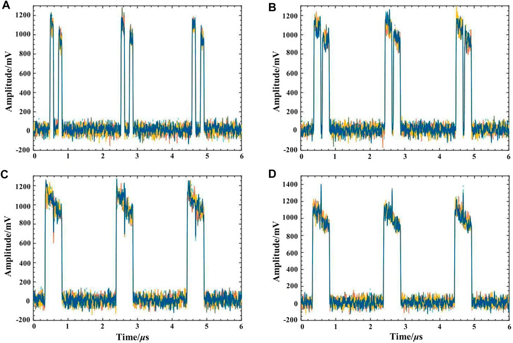
FIGURE 8. Dual pulse output when the repetition frequency is 10 kHz with different pulse durations of (A) 100 ns, (B) 150 ns,(C) 240 ns, and (D) 250 ns.
An experimental system is shown in Figure 9 to verify the ability of the proposed method to detect acoustic signals. The length of the FUT is 3 km long single-mode fiber (SMF). An arbitrary function generator (AFG) controls a piezoelectric ceramic transducer (PZT). The PZT simulates acoustic signals applied to 2 km of the FUT. In the experiments, the AOM shifted the light by 80 MHz. The PPG modulates the SOA so that the SOA-based FRL outputs an optical pulse with
Figure 10 shows the demodulation results when the modulation signal frequency with a peak amplitude of 1 V applied to the PZT is 1 kHz. A power spectral density (PSD) analysis is conducted with the demodulation results. The results are in the time domain and frequency domain.
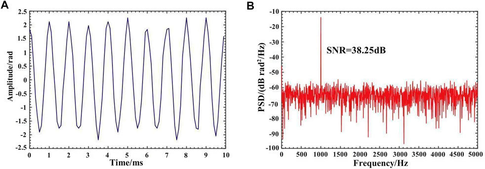
FIGURE 10. Demodulation results for 1 Vpp and 1 kHz signal (A) in time-domain trace (B) in the frequency domain.
A differential algorithm can be applied to the demodulated signal, allowing the acoustic signal to be located. Figure 11 shows the amplitude and phase variance results for a 1 Vpp and 1 kHz signal. The results agree well with the location of the PZT. The results imply that the system can localize the acoustic signal accurately.
The modulation signals applied to the PZT are varied with a fixed amplitude to demonstrate the system’s response to other frequencies. The sinusoidal signal applied to the PZT was fixed at a constant peak voltage of 1 V. The frequency was gradually changed for the measurement and demodulated, as shown in Figures 12, 13. As can be seen from the demodulation results, the system can accurately detect the acoustic signals at the fixed point of the fiber with a complete signal waveform. The spectrum also shows that the system can achieve a high SNR of 42.51 dB and accurately demodulate the signal frequencies.
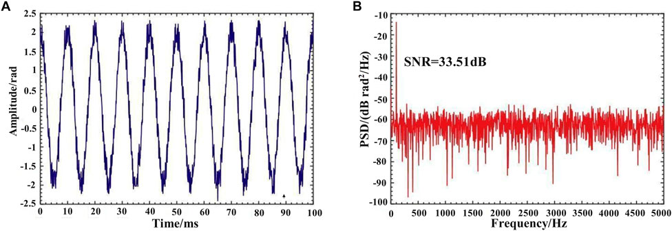
FIGURE 12. Demodulation results for 1 Vpp and 100 Hz signal (A) in time-domain trace (B) in the frequency domain.
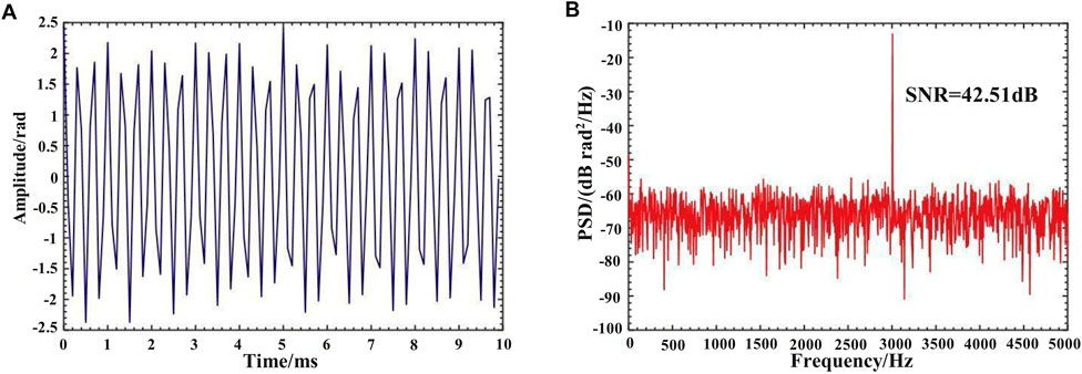
FIGURE 13. Demodulation results for 1 Vpp and 3 kHz signal (A) in time-domain trace (B) in the frequency domain.
The modulation signals applied to the PZT are varied in amplitude at a fixed frequency to demonstrate the system’s dynamic response. The sinusoidal signal applied to the PZT has been set at 3 kHz; the amplitude is 100 mV and 12 V, respectively, corresponding to 0.19 rad and 22.8 rad. The results of the demodulation are shown in Figures 14, 15. The demodulation results show that the system can accurately detect acoustic signals with different amplitudes.
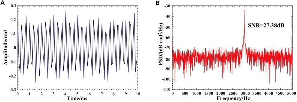
FIGURE 14. Demodulation results for 100 mVpp and 3 kHz signal (A) in time-domain trace (B) in the frequency domain.
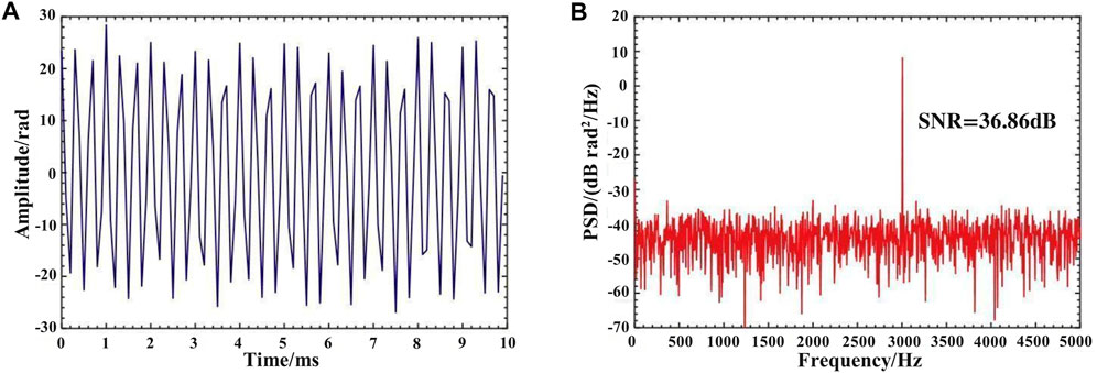
FIGURE 15. Demodulation results for 12 Vpp and 3 kHz signal (A) in time-domain trace (B) in the frequency domain.
The experimental results illustrate that the proposed system can detect acoustic signals with different frequencies and amplitudes. The demodulation and positioning results are accurate, fitting the modulation signals applied to the PZT well. For a 3 kHz acoustic signal, the SNR can achieve 42.51 dB. Above 100 Hz, the SNR of the demodulation results remained at 27.38 dB and above.
A dual pulse heterodyne DAS system is proposed by introducing SOA-based FRL in this paper. The proposed system is investigated theoretically and experimentally. The SOA-based FRL operates as a pulsed mode-locked laser, which replaces the NLL and pulse modulator, simplifying the system and reducing costs. A narrow linewidth optical pulse output can be obtained using the device, which fully exploits the gain and good switching characteristics of SOA. The effectiveness of the device is demonstrated in a dual pulse heterodyne DAS system. The proposed system achieves accurate demodulation and locatilization. The system’s frequency range is 5 Hz to 5 kHz, and a high SNR of 42.51 dB demodulation is achieved at 3 kHz. With a detection range of 10.2 km, the system’s spatial resolution is 12 m. The proposed system provides an alternative idea for DAS, significantly reducing the cost and simplifying the system. It is expected to greatly benefit from cost-effective, large-scale, and high-SNR applications in DAS. As the system can be modified by adding additional FBGs to support more laser wavelengths, further work will focus on multi-wavelength SOA-based FRL and its improvements. The multi-wavelength output is expected to benefit the practical applications of DAS greatly.
The original contributions presented in the study are included in the article/Supplementary Material, further inquiries can be directed to the corresponding author.
All authors listed have made a substantial, direct, and intellectual contribution to the work and approved it for publication.
The authors declare that the research was conducted in the absence of any commercial or financial relationships that could be construed as a potential conflict of interest.
All claims expressed in this article are solely those of the authors and do not necessarily represent those of their affiliated organizations, or those of the publisher, the editors and the reviewers. Any product that may be evaluated in this article, or claim that may be made by its manufacturer, is not guaranteed or endorsed by the publisher.
1. Dandridge A. Fiber optic interferometric sensors at sea. Opt Photon News (2019) 30(6):34. doi:10.1364/opn.30.6.000034
2. Toky A, Singh RP, Das S. Localization schemes for underwater acoustic sensor networks - a review. Comput Sci Rev (2020) 37:100241. doi:10.1016/j.cosrev.2020.100241
3. Lu B, Wu B, Gu J, Yang J, Gao K, Wang Z, et al. Distributed optical fiber hydrophone based on Phi-OTDR and its field test. Opt Express (2021) 29(3):3147–62. doi:10.1364/oe.414598
4. Almudévar A, Sevillano P, Vicente L, Preciado-Garbayo J, Ortega A. Unsupervised anomaly detection applied to Φ-OTDR. Sensors (2022) 22:6515. doi:10.3390/s22176515
5. Martins HF, Martin-Lopez S, Corredera P, Filograno ML, Frazao O, Gonzalez-Herraez M. Coherent noise reduction in high visibility phase-sensitive optical time domain reflectometer for distributed sensing of ultrasonic waves. J Lightwave Technol (2013) 31(23):3631–7. doi:10.1109/jlt.2013.2286223
6. Wang Z, Zhang L, Wang S, Xue N, Peng F, Fan M, et al. Coherent Φ-OTDR based on I/Q demodulation and homodyne detection. Opt Express (2016) 24(2):853–8. doi:10.1364/oe.24.000853
7. Soriano-Amat M, Martins HF, Durán V, Costa L, Martin-Lopez S, Gonzalez-Herraez M, et al. Time-expanded phase-sensitive optical time-domain reflectometry. Light Sci Appl (2021) 10(1):51. doi:10.1038/s41377-021-00490-0
8. Zhong X, Gui D, Zhang B, Deng H, Zhao S, Zhang J, et al. Performance enhancement of phase-demodulation ϕ-OTDR using improved two-path DCM algorithm. Opt Commun (2021) 482:126616. doi:10.1016/j.optcom.2020.126616
9. Zhong X, Zhang B, Ren J, Deng H, Chen X, Ma M. A novel $\phi$-OTDR system with a phase demodulation module based on sagnac balanced interferometer. J Lightwave Technol (2021) 39(22):7307–14. doi:10.1109/jlt.2021.3113082
10. Liu T, Wang F, Zhang X, Yuan Q, Niu J, Zhang L, et al. Interrogation of ultra-weak FBG array using double-pulse and heterodyne detection. IEEE Photon Technol Lett (2018) 30(8):677–80. doi:10.1109/lpt.2018.2811411
11. He X, Xie S, Liu F, Cao S, Gu L, Zheng X, et al. Multi-event waveform-retrieved distributed optical fiber acoustic sensor using dual-pulse heterodyne phase-sensitive OTDR. Opt Lett (2017) 42(3):442–5. doi:10.1364/ol.42.000442
12. Zinsou R, Liu X, Wang Y, Zhang J, Jin B. Recent progress in the performance enhancement of phase-sensitive OTDR vibration sensing systems. Sensors (2019) 19(7):1709. doi:10.3390/s19071709
13. Ibrahim ADA, Abbas K, Linda BE. SNR enhancement by DWT for improving the performance of Φ-OTDR in vibration sensing. Photon Switching Comput (2022) 5.
14. Qin Z, Chen L, Bao X. Wavelet denoising method for improving detection performance of distributed vibration sensor. IEEE Photon Technol Lett (2012) 24(7):542–4. doi:10.1109/lpt.2011.2182643
15. Shi Y, Feng H, Zeng Z. A long distance phase-sensitive optical time domain reflectometer with simple structure and high locating accuracy. Sensors (2015) 15:21957–70. doi:10.3390/s150921957
16. Qin Z, Chen H, Chang J. Detection performance improvement of distributed vibration sensor based on curvelet denoising method. Sensors (2017) 17:1380. doi:10.3390/s17061380
17. Qu S, Chang J, Cong Z, Chen H, Qin Z. Data compression and SNR enhancement with compressive sensing method in phase-sensitive OTDR. Opt Commun (2019) 433:97–103. doi:10.1016/j.optcom.2018.09.064
18. Li D, Lou S, Xin Q, Liang S, Sheng X. SNR enhancement of far-end disturbances on distributed sensor based on phase-sensitive optical time-domain reflectometry. IEEE Sens J (2021) 21(2):1957–64. doi:10.1109/jsen.2020.3019838
19. He H, Shao L, Li H, Pan W, Luo B, Zou X, et al. SNR enhancement in phase-sensitive OTDR with adaptive 2-D bilateral filtering algorithm. IEEE Photon J (2017) 9(3):1–10. doi:10.1109/jphot.2017.2700894
20. Adeel M, Tejedor J, Macias-Guarasa J, Lu C. Improved perturbation detection in direct detected -otdr systems using matched filtering. IEEE Photon Technol Lett (2019) 31(21):1689–92. doi:10.1109/lpt.2019.2940297
21. Muanenda Y, Oton CJ, Faralli S, Di Pasquale F. A cost-effective distributed acoustic sensor using a commercial off-the-shelf DFB laser and direct detection phase-OTDR. IEEE Photon J (2016) 8:1–10. doi:10.1109/jphot.2015.2508427
22. Wang Z-N, Zhang B, Xiong J, Fu Y, Lin S, Jiang J, et al. Distributed acoustic sensing based on pulse-coding phase-sensitive OTDR. IEEE Internet Things J (2019) 6:6117–24. doi:10.1109/jiot.2018.2869474
23. Soriano-Amat M, Martins HF, Duran V, Martin-Lopez S, Gonzalez-Herraez M, Fernández-Ruiz MR. Quadratic phase coding for SNR improvement in time-expanded phase-sensitive OTDR. Opt Lett (2021) 46(17):4406–9. doi:10.1364/ol.432350
24. Martins HF, Martín-López S, Corredera P, Ania-Castanon JD, Frazao O, Gonzalez-Herraez M. Distributed vibration sensing over 125 km with enhanced SNR using phi-OTDR over a URFL cavity. J Lightwave Technol (2015) 33:2628–32. doi:10.1109/jlt.2015.2396359
25. Choi KN, Taylor HF. Spectrally stable Er-fiber laser for application in phase-sensitive optical time-domain reflectometry. Photon Technol Lett IEEE (2003) 15(3):386–8. doi:10.1109/lpt.2003.807905
26. Qian H, Luo B, He H, Zhang X, Zou X, Pan W, et al. Phase demodulation based on DCM algorithm in Φ-OTDR with self-interference balance detection. IEEE Photon Technol Lett (2020) 32:473–6. doi:10.1109/lpt.2020.2979030
27. Martins HF, Martín-López S, Corredera P, Filograno ML, Frazao O, Gonzalez-Herraez M. Phase-sensitive optical time domain reflectometer assisted by first-order Raman amplification for distributed vibration sensing over >100 km. J Lightwave Technol (2014) 32:1510–8. doi:10.1109/jlt.2014.2308354
28. Pastor-Graells J, Nuño J, Fernández-Ruiz MR, Garcia-Ruiz A, Martins HF, Martin-Lopez S, et al. Chirped-pulse phase-sensitive reflectometer assisted by first-order Raman amplification. J Lightwave Technol (2017) 35:4677–83. doi:10.1109/jlt.2017.2756558
29. Du L, Shen Y, Yang S, Liang Y. Research on RP-EDF amplification characteristics based on φ-OTDR system. Optik: Z Licht- Elektronenoptik: = J Light-and Electronoptic. (2022) 262:169029. doi:10.1016/j.ijleo.2022.169029
30. Muanenda Y Recent advances in distributed acoustic sensing based on phase-sensitive optical time domain reflectometry. J Sens (2018) 2018(1):1–16. doi:10.1155/2018/3897873
31. Liu X, Jin B, Bai Q, Wang Y, Wang D, Wang Y. Distributed fiber-optic sensors for vibration detection. Sensors (2016) 16(8):1164. doi:10.3390/s16081164
32. Aktas M, Maral H, Akgun T. A model-based analysis of extinction ratio effects on phase-OTDR distributed acoustic sensing system performance. SPIE Conf Phys Simulation Optoelectronic Devices (2018).
33. Chen Y, Mao B-M, Zhou B, Guo C, Lin Z. Improving the SNR of the phase-OTDR by controlling the carrier in the SOA. J Mod Opt (2020) 67:1241–6. doi:10.1080/09500340.2020.1827071
34. Zulkifli MZ, Hassan NA, Awang NA, Ghani Z, Harun S, Ahmad H. Multi-wavelength fiber laser in the S-band region using a Sagnac loop mirror as a comb generator in an SOA gain medium. Laser Phys Lett (2010) 7(9):673–6. doi:10.1002/lapl.201010046
35. Madrigal J, Fraile-Peláez FJ, Zheng D, Barrera D, Sales S. Characterization of a FBG sensor interrogation system based on a mode-locked laser scheme. Opt Express (2017) 25(20):24650–7. doi:10.1364/oe.25.024650
36. Slepneva S, Kelleher B, O’Shaughnessy B, Hegarty S, Vladimirov A, Huyet G. Dynamics of Fourier domain mode-locked lasers. Opt Express (2013) 21(16):19240–51. doi:10.1364/oe.21.019240
37. Todor S, Biedermann B, Huber R, Jirauschek C. Balance of physical effects causing stationary operation of Fourier domain mode-locked lasers. J Opt Soc Am B (2012) 29(4):656–64. doi:10.1364/josab.29.000656
38. Jirauschek C, Biedermann B, Huber R. A theoretical description of Fourier domain mode locked lasers. Opt Express (2009) 17(26):24013–9. doi:10.1364/oe.17.024013
39. Ahmed M, Yamada M. Influence of instantaneous mode competition on the dynamics of semiconductor lasers. IEEE J Quan Electron (2002) 38(6):682–93. doi:10.1109/jqe.2002.1005419
40. Reale A, Di Carlo A, Lugli P. Gain dynamics in traveling-wave semiconductor optical amplifiers. IEEE J Sel Top Quan Electron (2001) 7(2):293–9. doi:10.1109/2944.954142
41. Feng X, Tam H-Y, Liu H, Wai P. Multiwavelength erbium-doped fiber laser employing a nonlinear optical loop mirror. Opt Commun (2006) 268(2):278–81. doi:10.1016/j.optcom.2006.07.010
42. Yamada M Theory of mode competition noise in semiconductor injection lasers. IEEE J Quan Electron (1986) 22(7):1052–9. doi:10.1109/jqe.1986.1073087
43. Hu Z, Davanco M, Blumenthal DJ. Extinction ratio improvement by strong external light injection and SPM in an SOA for OTDM pulse source using a DBR laser diode. IEEE Photon Technol Lett (2003) 15(10):1419–21. doi:10.1109/lpt.2003.818258
44. Connelly MJ. Wideband semiconductor optical amplifier steady-state numerical model. IEEE J Quan Electron (2001) 37(3):439–47. doi:10.1109/3.910455
45. Park J, Lee W, Taylor HF. Fiber optic intrusion sensor with the configuration of an optical time-domain reflectometer using coherent interference of Rayleigh backscattering. Opt Fiber Optic Sensor Syst (1998).
46. Gao X, Hu W, Dou Z, Li K, Gong X. A method on vibration positioning of Φ-OTDR system based on compressed sensing. IEEE Sens J (2022) 22(16):16422–9. doi:10.1109/jsen.2022.3191863
Keywords: fiber optical sensor (FOS), distributed acoustic sensor (DAS), rayleigh backscattering (RBS), sound wave detection, heterodyne demodulation, semiconductor optical amplifier (SOA), fiber ring laser (FRL)
Citation: Zhang C, Yang S and Wang X (2023) Dual pulse heterodyne distributed acoustic sensor system employing SOA-based fiber ring laser. Front. Phys. 11:1196067. doi: 10.3389/fphy.2023.1196067
Received: 29 March 2023; Accepted: 10 May 2023;
Published: 18 May 2023.
Edited by:
Xukun Yin, Xidian University, ChinaReviewed by:
Baoquan Jin, Taiyuan University of Technology, ChinaCopyright © 2023 Zhang, Yang and Wang. This is an open-access article distributed under the terms of the Creative Commons Attribution License (CC BY). The use, distribution or reproduction in other forums is permitted, provided the original author(s) and the copyright owner(s) are credited and that the original publication in this journal is cited, in accordance with accepted academic practice. No use, distribution or reproduction is permitted which does not comply with these terms.
*Correspondence: Sufan Yang, eWFuZ3N1ZmFuQGJ1YWEuZWR1LmNu
Disclaimer: All claims expressed in this article are solely those of the authors and do not necessarily represent those of their affiliated organizations, or those of the publisher, the editors and the reviewers. Any product that may be evaluated in this article or claim that may be made by its manufacturer is not guaranteed or endorsed by the publisher.
Research integrity at Frontiers

Learn more about the work of our research integrity team to safeguard the quality of each article we publish.