 Bing Dong
 Shoufeng Tong1*
94% of researchers rate our articles as excellent or good
Learn more about the work of our research integrity team to safeguard the quality of each article we publish.
Find out more
BRIEF RESEARCH REPORT article
Front. Phys., 05 May 2023
Sec. Optics and Photonics
Volume 11 - 2023 | https://doi.org/10.3389/fphy.2023.1195052
This article is part of the Research TopicAdvances in High-Power Lasers for Interdisciplinary ApplicationsView all 23 articles
In order to achieve underwater wireless dynamic optical communication, a laser communication system is proposed based on Pulse Position Modulation (PPM). In order to achieve underwater laser communication accurately, the mathematical model of underwater laser communication was constructed with small angle analysis. The pulse position modulation demodulation algorithm is designed, and the workflow of modulation and demodulation is given in the transmit module and the receive module. In the experiment, Lumileds-470 nm light source was selected for data communication for testing at a communication rate of 15 Mbp/s. In the servo control process, the square wave signal used for stepping motor drive had a stable amplitude output and a stable time width. It can well simulate the testing process of underwater dynamic scanning. In the experiment, laser light spots were obtained under different attenuation states, and the characteristics of the light spot distribution were analyzed. The numerical reconstruction of the light spot energy was completed in MATLAB. Three types of light attenuators, 1.0%, 0.1%, and 0.01%, were used to simulate different light attenuations underwater. The test results show that the system error rate is better than 10−6 when attenuation chip is 1.0%. When attenuation chip is 0.1%, the error rate of the system is reduced to 10−4. When attenuation chip is 0.01%, a valid signal cannot be obtained by the system. The feasibility of the system is verified.
Underwater wireless communication technology is widely used in resource exploration [1], abnormal sea state monitoring [2], sensor monitoring [3], underwater imaging [4], underwater robots [5], and airspace integration [6]. It is important advantages for blue or green laser, such as good penetration ability, strong anti-interference, large communication depth, and high transmission rate in seawater. It has become a research hotspot.
The characteristics of underwater laser communication include: a) high transmission rate. Due to the use of high-frequency information transmission, the transmission rate can reach Mbit/s, far due to traditional acoustic equipment. b) Large information capacity. The blue light of laser communication is about 620 THz, which can support the construction of large capacity link systems. It has the underwater transmission requirements of image signals and multi-channel video signals, and its high bit rate is generally around the GHz level. c) Strong anti-interference. The laser transmission process is not affected by electromagnetic interference. It is not significantly affected by seawater temperature, concentration, etc. d) High safety and density. Light wave has strong directionality and small beam divergence angle. If the communication signal is truncated, the receiving end will lose the signal, which is easy to be detected in a timely manner, so its security and confidentiality are very good. e) The system structure is compact. Underwater laser communication systems have a compact structure and low power, making them more concealable.
Duntley [7] found that lasers with a wavelength range of 470–525 nm can effectively reduce the light wave absorption of seawater. Shimura S [8] had experimentally verified that the visible light band has a low loss window, and its propagation loss was only 1% of that of other light waves. This discovery will have greatly advanced for the underwater laser communication research. Tivey et al. [9] developed an underwater wireless communication system. It still had the ability to transmit data underwater. The system achieves effective communication of signals within a range of 5 m. Huang A P et al. [10] designed an optical communication system with acoustic systems. This system used low-power receivers and it could achieve underwater data transmission of 10–20 Mbit/s within 100 m. Campagnaro F et al. [11] used a 405 nm wavelength laser to conduct communication tests in 4.8 m long clear water, when the communication rate is 1.45 Gbit/s, the bit error rate is only 9.1 × 10⁻⁴. Fu et al. [12] studied the impact of communication aperture on the bit error rate of underwater wireless optical communication systems under medium intensity turbulence. Han et al. [13] used electro-optical crystal modulation to generate communication signals, and completed the extinction characteristics of underwater communication systems on modulated signals by Monte Carlo method. Based on the analysis of transmission link span and laser divergence angle, Vali et al. [14] analyzed and discussed the effects of system aperture and field of view on underwater communication under turbulent conditions.
In summary, this paper studies an underwater laser communication system based on PPM (Pulse Position Modulation [15]) modulation. The system uses a servo mechanism to align the optical path at both ends of the laser communication, then uses PPM modulation technology to complete data communication, and simulates underwater communication by using an attenuator.
In this paper, a blue laser communication experimental system based on PPM modulation and demodulation is constructed. The overall structure of the system is shown in Figure 1.
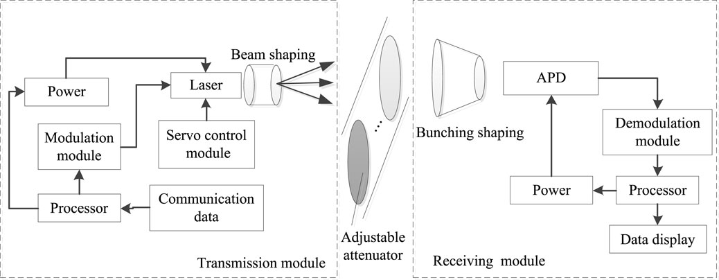
FIGURE 1. Receiving and transmitting module of underwater laser communication system.
The entire laser communication system consists of a transmitter and a receiver. The transmitter is mainly composed of a data transmission module, a PPM modulator, and a laser. The data transmission module is used to input the data to be transmitted and transmit it to the PPM modulator through USB interface. The PPM modulator converts the modulated data into an output signal and drives the laser to emit light through the laser interface. A laser beam emits a signal in the form of a carrier wave. The laser adopts a tunable semiconductor blue laser with a central wavelength of 470 nm and a maximum communication rate of 15 Mbps. In the experiment, in order to simulate the optical attenuation effect from 10 to 20 m underwater, variable optical attenuators were added to the communication path, achieving 30%, 50%, and 80% optical attenuation, respectively. In actual experiments, the distance between the two laser communication modules after using the attenuator will be set to be 2–4 m.
The receiving module is mainly composed of a receiving optical path, a PPM demodulator, and a data receiving terminal. After the certain attenuation, the laser pulse containing modulation information is transmitted to the receiving optical path. After photoelectric conversion is completed by the APD (Avalanche Photodetector [16]) detector, it is sent to the PPM demodulation module. The demodulated data can be displayed on the LCD panel of the PPM demodulator. Data can also be transferred to a computer through a USB port to complete operations such as storing and recording.
Small angle analysis is a typical method for studying underwater laser propagation [17]. During communication, the laser transmitter and receiver can achieve good position alignment through a servo mechanism, so their transmission divergence angle is small. The mathematical model is constructed from the particle nature of light, and the scattering process between photons and suspended particles is described using a small angle approximation method, which is more consistent with the actual test situation.
The laser beam is transmitted in water along the z-axis, and the light source coordinates are set to the origin (0, 0, 0). During transmission, seawater molecules and impurity molecules can cause laser light to scatter, assuming this scattering angle is θ i.
The movement displacement L per unit time is
x, y, z represents the numerical value on the corresponding coordinate axis, and t represents time. According to the scattering theory, assume that the single scattering rate is w, the unilateral scattering angle is θ, and the optical thickness is τ. There are
Then r is the photon scattering projection angle.
Due to the small value of r, the above formula can be simplified and approximated as follows:
According to the principle of optical communication [18], it is possible to calculate the time delay of the small angle analysis method as follows:
Where c is the speed of light and n is the refractive index of the water transmitting medium [19]. Therefore, the optical power at the receiving end of the system can be expressed as
Then EL is the energy value of the received light. In communication systems, the width of laser pulses affects time domain broadening. After the laser pulse passes through the water, since only the pulse broadening is considered, the shock response of the initial time domain waveform p (t) can be assumed to be Pc (t). After the transmission distance z of the initial pulse p (t), the broadened waveform can be expressed as
I(t) represents the energy value that varies with time t. From this energy value, the energy distribution of the communication laser spot at the receiving end can be calculated, thereby completing the inversion of communication efficiency.
The PPM communication pulse sequence is composed of several frames, each frame being divided into protection segments and information segments. When a pulse is included in the K time slots of the communication period, the pulse width is set to ΔT. One frame period is equivalent to one optical pulse period, which is also the repetition frequency of the laser.
The protection segment is related to the characteristics of the laser and is the minimum time interval for the laser to reach the threshold condition again. Use J light pulse lengths JΔT represents. K determines the number of bits k of modulated information, which can be expressed as:
In PPM modulation, the transmitted information corresponds to the position of the laser pulse one by one. The analysis of the pulse position can calculate the transmitted data value, which belongs to a phase modulation.
PPM modulation transmits information using a laser pulse from K time slots in the information segment. In a system, a frame period is the period of a light pulse, i.e., (K + J)ΔT. When the energy of a single laser pulse is high, the average power over the entire cycle is very small, reducing the need for average power in signal transmission. In terms of transmission rate, PPM modulation achieves log2M bit data transmission, and its speed can be expressed as
To further improve speed, you can increase the information time slot or reduce the protection time slot. However, this increase and decrease is not arbitrary, and is limited by the characteristics of the laser.
The laser emission module with a microprocessor as its core achieves timing output through a high-speed timer. Controllable output at a certain port is achieved by controlling the timer amount. Specific process: First, the timer operates in a high-speed timing state, and counts with the minimum resolution time slot. Then, when the algorithm controls the time corresponding to the modulated information data, a pulse is generated, and the rising edge of the pulse is its modulation information. Next, a similar rising edge is generated through the PPM conversion module to control this narrow pulse and complete the PPM modulation output. Finally, the output signal can be connected to the modulation interface of the laser to control the laser to emit a modulated optical pulse sequence.
The PPM demodulator, as the core device of the reception section, converts the received pulses containing modulation information into slot positions and demodulates the information. Firstly, it is implemented using the comparison and capture module of high-speed timers. As long as the received signal meets the trigger conditions after processing, it can accurately capture the pulse jump edge and achieve accurate timing. Secondly, a high-speed clock is used for timing decisions, and the positions of each pulse are recorded in the form of time counts. Finally, the modulation information is obtained through the corresponding demodulation algorithm.
The main structure of the system includes a transmitting light module and a receiving light module. In the receiving module, the computer controls the modulation module to complete the uploading and modulation of data. In the receiving module, the computer controls the demodulation module to complete data download and demodulation. Lumileds-470 nm type light source is selected as the emission laser. At a communication rate of 15 Mbps, a single LED has a luminous power of about 200 mW and a divergence angle of 120°. The output power of the entire LED array is above 1 W, which can meet the system requirements. In the receiving module, the APD detector selected by Hamamatsu Company is C12702-12. The processing part uses ALINX’s AN108 A/D module and FPGA development board to work together. The system is shown in Figure 2.
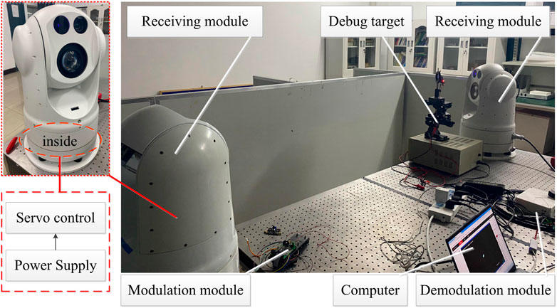
FIGURE 2. Laser communication experimental system.
Before the experimental test, first use a test target to calibrate the position of the receiving module and the transmitting module, and then add attenuation pads to the communication link to complete the simulation of underwater communication attenuation. The emitting laser spot is collected by the receiving end after passing through the medium. The original spot signal is restored through demodulation processing. Processing system is used to calculate the energy loss of the light spot, thereby analyzing the communication efficiency of the system.
Servo control modules are installed in the transmitting and receiving parts respectively, which are used to adjust the laser and detector by step scanning, thereby achieving effective alignment of communication angles. The servo control module is shown in Figure 3A, and its control response signal is shown in Figure 3B.
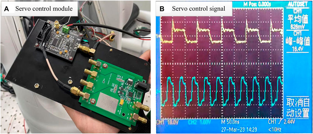
FIGURE 3. Wavelength offset values at different positions. (A) Servo control module. (B) Servo control signal
The system drives the stepper motor through a servo control module to achieve adjustable control of the position and angle of the optical module, achieving alignment of the irradiation position and posture during communication. By Figure 3B, the maximum signal value is 0.75 V, and the minimum signal value is 0.14 V in Ch1 channel. This is a control command issued by the control module that completes stepping control through a square wave level signal. After adjustment by the servo module, the corresponding command signal is displayed on the Ch2 channel. The maximum value of the signal in Ch2 channel is 2.41 V, and the minimum value is 1.23 V. After amplifying the step signal, the amplitude has significantly increased, and the time interval has not changed. This control module can effectively control the scanning system through a stepper motor. In the servo system, a stepper motor is used to complete the scanning of the communication module, simulating the characteristics of underwater dynamic communication.
In underwater laser communication, the spot energy of the communication laser is an important indicator to judge the communication quality. The attenuation and turbulent disturbance of water on the laser spot can significantly affect the energy distribution characteristics of the laser spot. Therefore, it is necessary to measure the energy of laser spots with energy attenuation and turbulence disturbances. In the experiment, 50% attenuation plates were used to simulate the attenuation effect of seawater medium on laser light. The energy of the actual test laser spot obtained by the APD detector is shown in Figure 4A. The energy distribution is reconstructed using MATLAB software, as shown in Figure 4B.
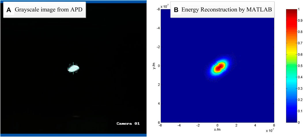
FIGURE 4. Laser spot acquisition and energy distribution reconstruction. (A) Grayscale image from APD. (B) Energy Reconstruction by MATLAB
As shown in Figure 4A, over a communication distance of 10 m, when 1.0% attenuation chip was used, the laser spot still undergoes significant deformation. When 0.1% attenuation chip was used, the energy peak decreases significantly and the signal-to-noise ratio decreases. When 0.01% attenuation chip was used, the laser communication receiver cannot obtain a valid signal. The deformation of the laser spot tends to be elliptical, and the analysis shows that its deviation angle is caused by alignment deviation between the receiving module and the transmitting module. This situation will exist in actual laser communication. On this basis, the energy distribution of the light spot is simulated and reconstructed, and the reconstruction results are shown in Figure 4B. The energy map shows that the energy distribution of the light spot is elliptical, consistent with the actual test results. The intensity of energy meets the energy requirements of laser communication, which can achieve effective information transmission.
As the pass rate of the attenuator decreases, the input power decreases. The laser spot energy becomes weaker, and the packet loss of communication data gradually increases. Under the condition of using 1.0% attenuator, the test results show that the error rate of the system is better than 10−6. Under the condition of using 0.1% attenuator, the test results show that the error rate of the system is better than 10−4. It can be seen that when the energy attenuation exceeds an order of magnitude, the bit error rate significantly increases. With a 0.01% attenuator, the effective signal is submerged in noise.
An underwater laser communication system was proposed based on PPM modulation. The system is mainly composed of a transmitting module and a receiving module. The system applies PPM modulation and demodulation technology to the transmitting module and the receiving module. The control of step scanning in the servo module was tested and analyzed in the experiment, for verifying the stability of clock matching. In the spot energy analysis test, the laser spot intensity at different attenuation states was obtained. The system communication error rate under different laser spot energy intensities was tested and studied. The feasibility of this system has been verified, and it has certain application prospects in the field of underwater laser communication.
The original contributions presented in the study are included in the article/supplementary material, further inquiries can be directed to the corresponding authors.
BD completed the paper. ST completed the system theoretical analysis. PZ completed the simulation calculation. JW completed the experimental test.
This work was supported in part by Natural Science Foundation of Jilin Province (YDZJ202301ZYTS394); Science and Technology Research Project of Jilin Provincial Department of Education (JJKH20230814KJ).
The authors declare that the research was conducted in the absence of any commercial or financial relationships that could be construed as a potential conflict of interest.
All claims expressed in this article are solely those of the authors and do not necessarily represent those of their affiliated organizations, or those of the publisher, the editors and the reviewers. Any product that may be evaluated in this article, or claim that may be made by its manufacturer, is not guaranteed or endorsed by the publisher.
1. Zhao Z, Bai Z, Jin D, Qi Y, Ding J, Yan B, et al. Narrow laser-linewidth measurement using short delay self-heterodyne interferometry. Opt Express (2022) 30(17):30600–10. doi:10.1364/OE.455028
2. Zhao Z, Bai Z, Jin D, Chen X, Qi Y, Ding J, et al. The influence of noise floor on the measurement of laser linewidth using short-delay-length self-heterodyne/homodyne techniques. Micromachines (2022) 13(8):1311. doi:10.3390/mi13081311
3. Xiang WD, Yang P, Wang S, Xu B, Liu H. Underwater image enhancement based on red channel weighted compensation and gamma correction model. Opto-Electronic Adv (2018) 1(10):18002401–9. doi:10.29026/oea.2018.180024
4. Sui MH. The key technology research on underwater wireless optical communication systems. Qingdao: Ocean University of China (2009).
5. Kim J, Joe H, Yu SC, Lee JS, Kim M. Time-delay controller design for position control of autonomous underwater vehicle under disturbances. IEEE Trans Ind Electro (2016) 63(2):1052–61. doi:10.1109/tie.2015.2477270
6. Zhang Y, Li X, Lv W, Chen J, Zheng M, Xu J, et al. Link structure of underwater wireless optical communication and progress on performance optimization. Opto-Electronic Eng (2020) 47(9):190734.
8. Shimura S, Ichimura SE. Selective transmission of light in the ocean waters and its relation to phytoplankton photosynthesis. J Oceanography (1973) 29(6):257–66. doi:10.1007/bf02108845
9. Tivey M, Fucile P, Sichel E. A low power, low cost, underwater optical communication system. Ridge (2000) 2(1):1–32.
10. Huang AP, Tao LW. Monte Carlo based channel characteristics for underwater optical wireless communications. Ieice Trans Commun (2017) 100(4):612–8. doi:10.1587/transcom.2016ebp3266
11. Gampagnaro F, Favaro F, Guerra F, Sanjuan V, Casari P Simulation of multimodal optical and acoustic communications in underwater networks. In: OCEANS 2015; May 18-21, 2015; Genoa, Italy. New York. IEEE (2015). p. 15473725.
12. Fu YQ, Huang CT, Du YZ. Effect of aperture averaging on mean bit error rate for UWOC system over moderate to strong oceanic turbulence. Opt Commun (2019) 451:6–12. doi:10.1016/j.optcom.2019.06.030
13. Han B, Wang W, Zheng Y, Shi K, Zhao W Influence of electro-optical crystal flatness on indirect modulation signal for underwater blue-green laser communication. Proc SPIE (2019) 11068:1106823.
14. Vali Z, Gholami A, Ghassemlooy Z, Michelson DG. System parameters effect on the turbulent underwater optical wireless communications link. Optik (2019) 198:163153. doi:10.1016/j.ijleo.2019.163153
15. Shen P, Yang L, Chen YS. Characteristics and development status of underwater laser communication technology. China Plant Eng (2018)(4) 214–5.
16. Wu T-C, Chi Y-C, Wang HY, Tsai CT, Lin GR. Blue laser diode enables underwater communication at 12.4 Gbps. Nature (2017) 25(13):40480–14765. doi:10.1038/srep40480
17. ValiGholami ZASGHAR, Ghassemlooy Z, Michelson DG, Omoomi M, Noori H. Modeling turbulence in underwater wireless optical communications based on Monte Carlo simulation. J Opt Soc America, A. Opt image Sci Vis (2021) 34(8):1187. doi:10.1364/josaa.34.001187
18. Chen H, Bai Z, Cai Y, Yang X, Ding J, Qi Y, et al. Order controllable enhanced stimulated Brillouin scattering utilizing cascaded diamond Raman conversion. Appl Phys Lett (2023) 122(9):092202. doi:10.1063/5.0137542
Keywords: laser communication, underwater communication, servo control, dynamic testing, PPM
Citation: Dong B, Tong S, Zhang P and Wang J (2023) Research on underwater wireless dynamic optical communication system based on PPM modulation. Front. Phys. 11:1195052. doi: 10.3389/fphy.2023.1195052
Received: 28 March 2023; Accepted: 19 April 2023;
Published: 05 May 2023.
Edited by:
Bofeng Zhu, Nanyang Technological University, SingaporeReviewed by:
Xiao Han, Harbin Engineering University, ChinaCopyright © 2023 Dong, Tong, Zhang and Wang. This is an open-access article distributed under the terms of the Creative Commons Attribution License (CC BY). The use, distribution or reproduction in other forums is permitted, provided the original author(s) and the copyright owner(s) are credited and that the original publication in this journal is cited, in accordance with accepted academic practice. No use, distribution or reproduction is permitted which does not comply with these terms.
*Correspondence: Shoufeng Tong, dHNmMTk5OEBzaW5hLmNvbQ==; Peng Zhang, enBAY3VzdC5lZHUuY24=
Disclaimer: All claims expressed in this article are solely those of the authors and do not necessarily represent those of their affiliated organizations, or those of the publisher, the editors and the reviewers. Any product that may be evaluated in this article or claim that may be made by its manufacturer is not guaranteed or endorsed by the publisher.
Research integrity at Frontiers
Learn more about the work of our research integrity team to safeguard the quality of each article we publish.