 Fei Yan
 Qi Li
Qi Li- National Key Laboratory of Science and Technology on Tunable Laser, Harbin Institute of Technology, Harbin, China
Introduction: Guided mode resonance is generated by coupling wave diffractions with the waveguided mode. The guided mode resonances provide narrow-linewidth and resonance intensity for high quality factor (Q-factor) optical resonators.
Methods: we demonstrate the high-Q guided mode resonances propagating on a low-loss, terahertz guided-mode magnetic resonance system, which are periodic square lattices of U-shaped split ring resonators (SRRs) on quartz substrates.
Results: By choosing a judicious array period, two distinct frequency guided mode resonances and a magnetic dipole resonance with high Q-factor are observed. The interaction of the two resonances at similar frequencies produces a total transmission peak.
Discussion: The dependences of the magnetic dipole resonance on the lattice period and structural parameters are investigated and discussed. The frequency difference between these two guided mode resonances widens with increasing Lattice period. The sharp spectral feature of each resonance results in the abrupt degradation of the spectral edge transmission. The proposed scheme is promising for efficient THz sensing, THz switching, and slow-light devices.
1 Introduction
Terahertz (THz) radiation has received great attentions owing to its potential advantages in many frontier fields, such as medical diagnosis, broadband communication, security, national defense, and biomolecular noninvasive sensing [1–4]. As a transition band between electronics and photonics, THz radiation has always been one of the important subjects across different branches of physics such as optics, electromagnetics, and nanophotonics [5–10]. THz technology has achieved significant progress, particularly in THz radiation sources, detectors and application research in sensing and imaging. However, various THz functional devices and physical phenomena are still need to be developed diligently. Especially in THz regime, the realization of the strong field-matter interaction has been in the exploratory stage and is urgent.
Guided mode resonances, arises from the coherent coupling of the grating diffraction field and waveguide modes under the conditions of the phase matching [11–14], which can be used to achieve THz resonant metasurfaces with high quality factors and frequency selective responses. Guided mode resonances with high quality-factor (Q-factor) plays an important role for ultra-sensitive label-free sensing. Recently, a variety of guided mode resonances have been presented to operate in the THz band [15–29], contributing greatly to the development of THz high-Q resonance. However, most reported works about THz high Q-factor guided-mode resonances focused on conventional electrical gratings [16–29], and few studies have reported guided-mode resonances in guided mode-magnetic resonance system. Moreover, it is still challenging to achieve both guided-mode resonance and magnetic resonance with ultrahigh-Q and large modulation depth in a resonant system, because the magnetic contribution is negligible in light-matter interactions, since because the effect of light on the magnetic permeability is much weaker than on the electric permittivity [30].
In the paper, we propose a guided-mode magnetic resonance system to produce extremely high Q-factor Fano guided-mode resonance in THz regime. High-Q guided mode resonances and magnetic dipole resonance with ultrahigh-Q and large modulation depth in a resonant system can be achieved in a low-loss, THz guided-mode magnetic resonance system, which are periodic square lattices of U-shaped SRRs on quartz substrates. The effects of lattice period and structural parameters on the magnetic dipole resonance are discussed. Choosing a judicious array period, two distinct different frequency guided mode resonances are observed. The interaction of the two resonances at similar frequencies produces a total transmission peak. The frequency difference between these two guided mode resonances widens with increasing Lattice period. The sharp spectral feature of each resonance results in the abrupt degradation at the spectral edge transmission. The proposed scheme holds great promise for practical applications for ultra-narrow THz filters.
2 Metasurface design and simulation
The proposed THz plasmonic metasurface resonator is depicted in Figure 1, with a sketch of unit cell, the relevant dimensional parameters and the polarization configuration (the electric (E) and magnetic (H) fields of the incident wave). The geometric center of the SRR is placed on orthocenter of the unit cell, as shown by the white dashed line. In contrast to plasmonic based guided-mode resonance devices, the advantage of the proposed structure is that the simple U-shaped SRRs simultaneously acts as low-loss magnetic resonator and a diffraction grating, supporting in the formation of THz guided-mode resonance and enabling distinct properties for transmission. In addition, the proposed structure has the characteristics of simplicity, better homogeneity, and easy processing.17,18 The optimized geometric parameters of the SRRs involve the super cell lattice constants of Px = Py = p = 160 μm, the two arms Lx = 30 μm, the backbone Ly = 50 μm, the split gap s = 40 μm, the width w = 5 μm, and the thickness of metal SRRs is 200 nm. The thickness of the quartz substrate is 300 μm.
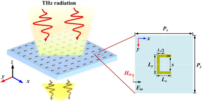
FIGURE 1. Structural schematic of the proposed THz plasmonic metasurfaces, with a unit cell and metal SRR zoomed in. The unit cell includes the relevant dimensional parameters and the polarization configuration.
Numerical simulations were carried out by utilizing commercially full-wave simulation software package COMSOL Multiphysics based on the finite element method (FEM). Periodic boundary conditions in both x and y directions along with perfectly matched layer is the z direction are applied to the metamaterial unit cell. Theoretical simulation techniques can be supported in recent papers [21, 22, 31]. The filtering properties of the resonator can occur normally when an infinite metasurface is fabricated into a finite sample [21, 22, 31]. The relative permittivity of gold is calculated by the Drude model as ε = 1-ωp2/(ω2+iγcω) in the THz regime, with plasma frequency ωp = 1.37 × 10¹⁶ rad/s and damping rate γc = 4.08 × 10¹³ rad/s [22, 32, 33]. The metals have excellent conductivity at THz frequencies, the ohmic losses of most metallic metamaterials are relatively quite low. The quartz substrate is taken as a lossless dielectric with relative electrical permittivity of 2.14 [31]. The plane waves are incident normally to the unit cell along the z direction with the x-polarization (perpendicular to the gap of SRRs). The transmittance coefficient is obtained by calculating the S-parameter.
3 Results and discussions
The transmission spectra with x-polarization incidence is shown in Figure 2A. It can be observed that when the lattice period is 160 μm (shown by the red line), a broadband dipolar resonance and two abrupt ultra-sharp Fano resonances with distinct narrow linewidth are excited at f1 = 0.886 THz, f2 = 0.931 THz and f3 = 0.940 THz with Δf of in the simulated transmission spectra, respectively. The Q-factor is defined as Q = 2πf0PS/PL = f0/Δf [22], where f0 is the resonant frequency, PS and PL are stored energy and dissipated energy, and Δf is the full width at half maximum. Thus, the Q-factor of the dipole resonance mode f1 is about 32. Intriguingly, it can also be observed that two abrupt ultrasharp resonances feature with ultrahigh Q-factor as high as 651 and 97 occur at f2 = 0.931 THz and f3 = 0.940 THz in the transmission spectra, as shows in Figure 2. Note that the energy radiation loss is generally large in SRRs magnetic resonant systems. The Q-factor of resonance in various THz magnetic systems is often difficult to break the limit of 15 experimentally, and the theoretical Q-factor is less than about 102 [31]. In such cases, the Q-factors of the order of 103 can be considered as high. The simulated modulation depth [(Tmax-Tmin)/(Tmax + Tmin) × 100%] for the three resonances are 90.6%, 95.2%, and 95.3%, respectively. Interestingly, as indicated by the green dot, the interaction of the two resonances at similar frequencies produces a total transmission peak. Interestingly, the THz guided-mode magnetic resonance system exhibits three total transmission peaks in the 0.8 to 1 THz range, which is appropriate for practical application to ultra-narrow multi-band filters.
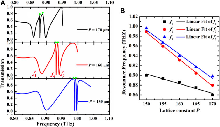
FIGURE 2. (A) The transmission of U-type arrays versus inverse lattice period; (B) The evolutions of resonant frequency of the three modes versus inverse lattice constant.
When the lattice period increases from 150 to 170 μm, all three resonance modes appear distinctly redshift, which is attributed to the reduction of the effective dielectric permittivity of the resonance response due to the geometric scale effect. The magnetic dipole mode becomes sharper, while the f2 mode and f3 mode appear the opposite behavior, accompanied by gradually increasing linewidth. When the lattice period is equal to 150 and 160 μm, the resonator exhibits high-Q full-transmittance at the green dot. As the lattice period increases, the peak transmission at the dot shows a gradual decrease, even when the period is equal to 170 μm, the transmission at the green dot can still be maintained at 80%. Figure 2B shows the resonant frequency for each mode as a function of the lattice period P of unit resonator. As seen in the plot, all three modes exhibit a noticeable red shift with increasing lattice constant. The resonant frequencies can be found to shift linearly as the lattice constant changed.
In order to deeply understand the fundamental nature and physical mechanism of these spectral resonances, when the lattice period is 160 μm, the surface current and magnetic field distributions at the three resonant frequencies (f1, f2, and f3) are calculated are given in Figure 3. The induced surface currents on the SRR are schematically illustrated by white arrows. For the resonance f1, from the Figure 3A, it can be a circular surface currents loop in the SRR are excited. The SRRs allow the formation of the fundamental-order magnetic dipole resonance at 0.886 THz with a circulating current. The fundamental-order magnetic dipole mode can be excited with a high Q-factor, and the physical mechanism is the coherent coupling of the purely magnetic dipole mode and the first-order (0,1) in-plane lattice surface mode [19]. As reported in our previous work [31], the strong coherent coupling between the magnetic dipole mode and the lattice mode enhances the Q-factor. However, in the previous work, for the fundamental-order magnetic dipole mode, we only characterized an experiment without specifically studying the dependence of transmission resonances on the structural parameters or other factors. In the present work, the high-Q transmission properties of the fundamental-order magnetic dipole mode are more theoretically studied and discussed.
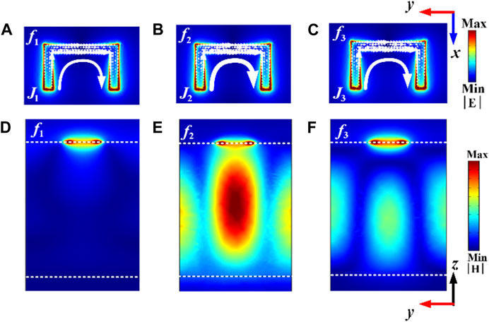
FIGURE 3. (A-C) surface current and (D-F) magnetic field distributions at the three resonance frequencies on the transmission spectra. The simulation results of current and field intensity are in arbitrary units (color coded). Notice the current and electric field intensities of guided-mode resonance f2 are much larger than f3. The color bar represents intensity distribution.
In contrast, as for the resonance f2 of 0.931 THz and the resonance f3 of 0.940 THz, from Figures 3B, C, it can be seen that the surface current remains a circular surface current loop. The excitation of standing-wave guided-mode make the probing field strongly confined in a gap cavity is observed, as shown in Figures 3E, F. From the electric field distribution in Figure 3D, it can be concluded that the first resonance f1 among the multiple resonances in Figure 2 originates from the magnetic dipole resonance of the metal ring, and the second resonance f2 and the third resonance f3 both exhibit the characteristics of the guided-mode resonances. Unlike the previous guided-mode resonances based on the metal pattern resonators [23–28], the metal ring also exhibits strong field distribution. In Figure 3E, the field distribution in the SRRs is similar to that in Figure 3D, which indicates that the magnetic dipoles are involved in the coupling. In Figure 3F, the field distribution at the middle of the metal is obviously different from that in Figures 3D, E, the metal SRR acts as a diffraction grating at resonant frequency f3. When the incident light impinges on the grating, the in-plane-wavevector-frequency relations of diffraction modes satisfy the dispersion relations of guided-mode resonances, the guided-mode resonance can be launched [34]. The second resonance originates from the Fano-type interference between the guided-mode resonance f3 and the magnetic dipole, accompanied by the significant electric field enhancement in the substrate layer. The results imply that the photon energy could be strongly confined into the substrate through diffraction coupling, which dramatically increases the energy stored (PS) by the subwavelength resonators. Resulting in low radiation loss and high Q factor. This implies that the low absorption and radiation losses occurring at resonance make a great contribution to ultra-narrow bandwidths, consequently producing ultrahigh Q-factors of 651 in f2 mode and 97 in f3 mode.
With the periodic lattice produced by the SRRs sitting on the substrate, guided-modes are generated in the substrate. The eigenvalue equation of guided-modes is obtained by [35–37].
Where
ky is the y-component of the incident wavevector, and Pg is the grating period. The theoretical derivations clearly show that for a guided-mode resonance, the resonance characteristics are strongly dependent on the grating period. Thus, the high-Q resonance response accompanied by a large modulation depth can be modulated and manipulated by changing the lattice period or structural size of the SRRs.
Table 1 summarizes the comparison of the proposed structure and dielectric metasurfaces. The proposed structures can be classified as plasmonic metasurfaces according to the material type, which are composed in metallic unit structures whose optical responses are driven by plasmon resonances supported by metallic particles [38]. For dielectric metasurfaces, the unit structure is composed of high refractive index dielectric resonators, including silicon, germanium or tellurium, where electric and magnetic dipole responses based on Mie resonances can be excited [38, 39].
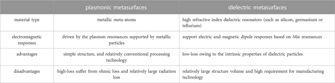
TABLE 1. The comparison of the proposed metasurfaces and dielectric metasurfaces.
In terms of high-Q resonance, the disadvantage of plasmonic metasurfaces is that the losses of the structure are usually higher, as metals tend to suffer from ohmic losses. The advantages of the proposed metasurfaces is that the structure is simpleand the processing technology is relatively conventional. However, dielectric metasurfaces have a great advantage for achieving high-Q resonances because the small loss of the structure is related to the intrinsic properties of dielectric particles. The structure volume of the dielectric supersurface is relatively large and have relatively high requirements of processing technology.
The effect of the thickness of substrate d on the three resonances is also investigated. As shown in Figure 4A, as the thickness of substrate increases from 220 to 300 μm, high-Q resonance transmission of three modes can be observed. The Q-factor of the fundamental-order magnetic dipole resonance is essentially constant, even though changing the substrate leads to a change in the line shape of the spectra. It’s different from that the spectra linewidth of the two guided-mode resonances exhibits a decreasing and then increasing feature, and the modulation depth also shows a decreasing and then increasing feature. This may be mainly related to the change of the phase matching conditions of the guided-modes due to the change of the substrate thickness [36]. Figure 4B shows the resonant frequency for each mode as a function of the substrate thickness d. The resonance frequency of the fundamental-order magnetic dipole resonance remains unchangeable, due to the fact that the magnetic resonance of the metal SRRs is mainly determined by the ring current. It can be seen that two guided-modes exhibit a distinct redshift towards low frequencies due to the reduction of the effective dielectric permittivity when the thickness of substrate d increases.
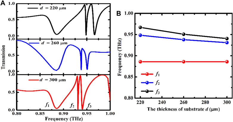
FIGURE 4. (A) Transmission spectra of the proposed scheme as a function of the substrate thickness d; (B) The evolutions of resonant frequency of the three modes when changing the substrate thickness d.
To highlight evolution of the three resonant modes, the lattice period is of great importance to the electromagnetic response of the proposed THz plasmonic metasurfaces. Here the influence of the lattice period P on the spectral response behavior is investigated. The Q-factors and modulation depths are plotted as functions of lattice constant P.
As shown in Figure 5A, when the period increases from 150 to 170 μm, the Q-factor exhibits an interesting exponential growth behavior versus the lattice period P. The dependence of the Q-factor of the f1 mode on the lattice period P is summarized as Qf1 = Q0 + A1exp [(P + D1)/B1], where the coefficients retrieved from numerical fitting are A1 = 3.12844, B1 = 6.30738, D1 = −150.826, respectively, and the fitting R-square is 0.9996, which is very close to unity. The modulation depth of f1 mode decreases from 93.7% to 81.7%, and the resonance response still maintains a large modulation depth. As shown in Figures 5B, C, when the period increases from 150 μm to 170 μm, the Q-factor of two Fano guided-mode resonances exhibits an exponential decreasing behavior versus the lattice period P. The dependence of the Q-factor of the f2 mode on the lattice period P is summarized as Qf2 = Q2 + A2exp (P/B1), where the fitting coefficients are: A2 = 7.91 × 10¹³, B2 = −5.84, Q2 = 565.76, respectively, and the fitting R-square is 0.995. The large modulation depth of f1 mode decreases from 95.7% to 86.3%. The dependence of the Q-factor of the f3 mode on the lattice period P is expressed as Qf3 = Q3+A3exp (P/B3), where the fitting coefficients are: A3 = 2.91×10¹⁴, B3 = −5.48, Q3 = 38.4, respectively, and the fitting R-square is 0.999. The modulation depth of f1 mode decreases from 95.2% to 90.9%. The exponentially increasing Q-factor rapidly because the cancellation of dipole moment in the U-SRRs is enhanced along with relatively lower radiative loss. However, the Q-factor of two Fano guided-mode resonances decreases exponentially with increasing lattice constant as a consequence of the fact that the diffraction guide mode effect will become weaker, resulting in relatively high radiative loss. It can be seen that the magnetic dipole mode and the Fano guided-mode resonances with extremely high Q-factor and large modulation depth mostly depends on the suitable lattice period.
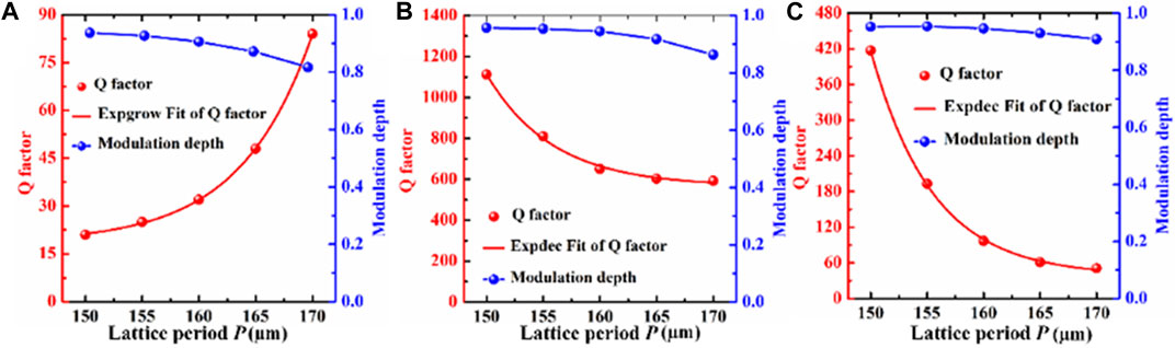
FIGURE 5. (A–C) The evolutions of Q-factors and modulation depth of the three modes versus inverse lattice period, respectively.
To further investigate transmission characteristics of high-Q resonances of THz plasmonic metasurfaces, we performed key parametric study of the effect of the arm Lx, the backbone Ly and split gap s on the behavior of the spectral responses. The simulated transmission spectra as a function of geometric parameters and resonance frequency each in a color map is shown in Figures 6A–C, respectively. Figures 6D–F are the variations of the Q-factor with the change of geometric parameters. As shown in Figure 6A, with the increase of the arm Lx, the transmission spectra of the ω1 mode and the ω3 mode exhibit a distinct redshift, while the ω2 mode exists a slight redshift, and its resonance frequency remains basically unchanged. Interestingly, with the increase of Lx from 15 μm to 35 μm, the resonance linewidth of the ω1 mode gradually increases, the resonance linewidth of the ω2 mode shows a slight increase first and then decreases, while the ω3 mode manifests a clear increase first and then decrease. This is because the loss mechanisms of the three resonances are obviously different. The corresponding Q-factor is shown in Figure 6D, as the Lx of the resonator gradually increases, the resonance linewidth changes differently, and the loss of the resonator is different. The Q-factor of the ω1 mode gradually decreases from 2400 to 96, and finally in a saturated state, the Q-factor of the ω2 mode first decreases and then increases from about 4200 to about 900, and the Q-factor of the ω3 mode also decreases first and then increases from about 400 to about 400.
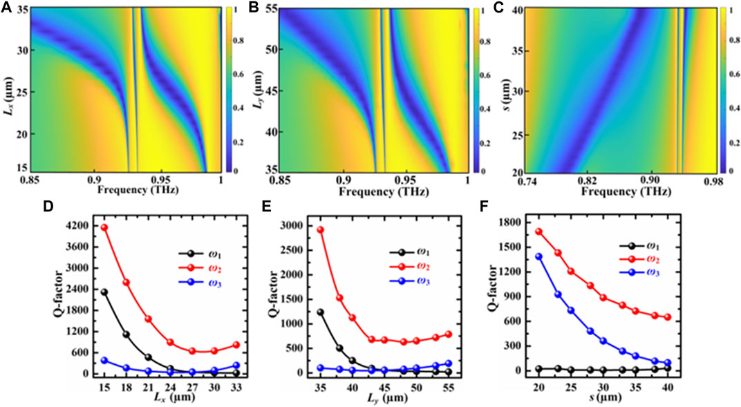
FIGURE 6. (A–C) are the spectral transmission as a function of the operating frequency and structural parameters, respectively at the three geometric parameters of Lx, Ly and s. (D–F) represent the variation of Q-factor with geometric parameters Lx, Ly and s, respectively.
Similarly, as shown in Figure 6B, as the backbone Ly increases from 35 to 55 μm, the transmission spectra of the ω1 mode and the ω3 mode also show significant redshift, and the ω2 mode shows a slight redshift. Due to the increase of radiation damping caused by the size mismatch, all of modes still remain at high level. Figure 6C depicts the simulated transmission spectra for a sweep of the split gap s from 20 to 40 μm. Obviously, both the resonances ω1 and ω3 for the SRRs appear distinctly blue shift towards higher frequencies due to the decreased capacitive coupling in the structure when the split gap s is increased, but the resonance frequency of the ω2 mode remains unchanged. Both the ω2 and ω3 modes exhibit gradual broadening as the split gap enlarged. The Q-factor of the magnetic resonance ω1 and guided mode resonances (ω2 and ω3) as a function of split gap s has also been extracted, as shown in Figure 6F. In the ω1 mode, the Q-factor can be stably maintained during the whole operation, but show a slight floating. However, unlike resonance mode ω1, the resonance mode ω2 and ω3 show a decreasing trend. This is because the excitation principles of magnetic resonance and guided-mode resonance are different in nature.
With the increase of the gap s from 20 to 40 μm, the Q-factor of resonance mode ω2 drops from about 1700 to about 750, and the Q-factor of resonance mode ω3 is reduced from about 1400 to about 100. The results suggest that proposed THz plasmonic metasurfaces possessing magnetic resonance and double sharp guided-mode resonances with adjustable Q-factor and modulation depth could be used for versatile applications by choosing an appropriate geometric parameter. Table 2 summarizes a comparison of the performance with respect to the state-of-the-art schemes. Compared with previous typical achievements [21, 22, 26, 28], the proposed structure can easy to excite low-loss magnetic dipole mode and guided-mode resonances simultaneously, avoiding a complex patterned metal metamaterial.
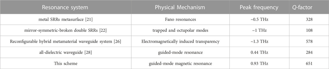
TABLE 2. A comparison of the performance with respect to the state-of-the-art schemes.
4 Potential fabrication process
The proposed structure can be fabricated by regular photolithography technology due to structure feature size exceeding a few micrometers [31], which can support the feasibility of the scheme for measurements. A set of the main feasible steps of the SRRs array metasurfaces production process is shown in Figure 7. In general, Au pattern layer with a thickness of t = 200 nm is deposited on a 300 µm thick quartz substrate. Au is chosen because it is stable and hardly oxidated in air.
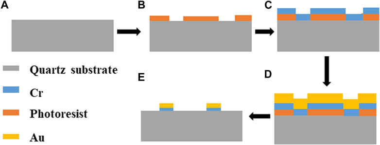
FIGURE 7. Sample fabrication process. (A) Deposition of quartz substrate; (B) Spin coating of photoresist. (C) Magnetron sputtering of Cr; (D) Magnetron sputtering of Au; (E) Target graphic structure obtained by lift-off technique.
As the adhesion between Au and quartz substrate is not strong, the adhesion between Cr and quartz substrate and Au are very good, and Cr is chosen as the adhesion layer [40]. Note that the thickness of the Cr layer is so thin that it has a negligible effect on the resonance. As shown in Figure 7, Firstly, the quartz substrate is pretreated to remove surface contaminants; secondly, the spin coating of photoresist is performed on the quartz substrate [41]; Then, a 10 nm thickness of Cr is grown on the structure surface by using magnetron sputtering to enhance the adhesion of the metal layer to the substrate [42]; Subsequently, the growth of a 200 nm thick metallic film is continued by magnetron sputtering deposition, and the target coating is applied on the mask plate; Finally, the lift-off is used to obtain the target graphic structure by dissolving the photoresist or mechanically removing the metal hard mask using a stripping solution [43]. The potential challenges can arise during the manufacturing process, including the requirement of manufacturing precision and the influence of the fabrication errors on the THz response, and it is important to avoid these whenever possible.
5 Conclusion
To summarize, we have presented an ultra-narrow guided mode resonances and magnetic dipole resonance with an ultrahigh Q-factor and large modulation depth. The proposed structure is composed of a U-shaped SRRs array and a quartz substrate. In THz guided-mode magnetic resonance system, the cavity-enhanced interaction in resonant guided modes brings about ultra-narrowband sharp resonance of large modulation depth at an ultrahigh Q-factor. The transmission dependences of the magnetic dipole resonance and guided-mode resonances on the lattice period and structural parameters are investigated and discussed. The proposed scheme is very promising for development of ultra-narrow multi-band filters at THz frequency.
Data availability statement
The original contributions presented in the study are included in the article/Supplementary Material, further inquiries can be directed to the corresponding author.
Author contributions
FY: Data curation (lead); Investigation (lead); Writing—Original draft (lead). QL: Funding acquisition (lead); Project administration (lead); Resources (lead); Supervision (lead). ZW: Data curation (equal). All authors listed have made a substantial, direct, and intellectual contribution to the work and approved it for publication.
Conflict of interest
The authors declare that the research was conducted in the absence of any commercial or financial relationships that could be construed as a potential conflict of interest.
Publisher’s note
All claims expressed in this article are solely those of the authors and do not necessarily represent those of their affiliated organizations, or those of the publisher, the editors and the reviewers. Any product that may be evaluated in this article, or claim that may be made by its manufacturer, is not guaranteed or endorsed by the publisher.
References
1. Kutas M, Haase B, Bickert P, Riexinger F, Molter D, Freymann GV Terahertz quantum sensing. Sci Adv (2020) 6(11):8065. doi:10.1126/sciadv.aaz8065
2. Han S, Cong L, Srivastava YK, Qiang B, Rybin MV, Kumar A, et al. All-dielectric active terahertz photonics driven by bound states in the continuum. Adv Mater (2019) 31:1901921. doi:10.1002/adma.201901921
3. Nagel M, Bolivar PH, Brucherseifer M, Kurz H, Bosserhoff A, Büttner R. Integrated THz technology for label-free genetic diagnostics. Appl Phys Lett (2002) 80(1):154–6. doi:10.1063/1.1428619
4. Tonouchi M Cutting-edge terahertz technology. Nat Photon (2007) 1(2):97–105. doi:10.1038/nphoton.2007.3
5. Arikawa T, Hiraoko T, Morimoto S, Blanchard F, Tani S, Tanaka T, et al. Transfer of orbital angular momentum of light to plasmonic excitations in metamaterials. Sci Adv (2020) 6(24):1977. doi:10.1126/sciadv.aay1977
6. Valentine J, Zhang S, Zentgraf T, Ulin-Avila E, Genov DA, Bartal G, et al. Three-dimensional optical metamaterial with a negative refractive index. Nature (2008) 455(7211):376–9. doi:10.1038/nature07247
7. Gupta M, Srivastava YK, Singh R A toroidal metamaterial switch. Adv Mater (2018) 30(4):1704845. doi:10.1002/adma.201704845
8. Cojocari MV, Schegoleva KI, Basharin AA Blueshift and phase tunability in planar THz metamaterials: The role of losses and toroidal dipole contribution. Opt Lett (2017) 42(9):1700–3. doi:10.1364/ol.42.001700
9. Seren HR, Zhang J, Keiser GR, Maddox SJ, Zhao X, Fan K, et al. Nonlinear terahertz devices utilizing semiconducting plasmonic metamaterials. Light Sci Appl (2016) 5(5):e16078. doi:10.1038/lsa.2016.78
10. Chen H-T, Padilla WJ, Cich MJ, Azad AK, Averitt RD, Taylor AJ A metamaterial solid-state terahertz phase modulator. Nat Photon (2009) 3(3):148–51. doi:10.1038/nphoton.2009.3
11. Hayashi S, Nesterenko DV, Rahmouni A, Sekkat Z Observation of Fano line shapes arising from coupling between surface plasmon polariton and waveguide modes. Appl Phys Lett (2016) 108(5):051101. doi:10.1063/1.4940984
12. Mendis R, Nag A, Chen F, Mittleman DM A tunable universal terahertz filter using artificial dielectrics based on parallel-plate waveguides. Appl Phys Lett (2010) 97(13):131106. doi:10.1063/1.3495994
13. Uddin MJ, Magnusson R Efficient guided-mode-resonant tunable color filters. IEEE Photon Technol. Lett. (2012) 24(17):1552–4. doi:10.1109/lpt.2012.2208453
14. Bark HS, Kim GJ, Jeon T-I Transmission characteristics of all-dielectric guided-mode resonance filter in the THz region. Sci Rep (2018) 8(1):13570. doi:10.1038/s41598-018-31931-3
15. Uddin MJ, Khaleque T, Magnusson R Guided-mode resonant polarization-controlled tunable color filters. Opt Express (2014) 22(10):12307–15. doi:10.1364/oe.22.012307
16. Uddin MJ, Magnusson R Guided-mode resonant thermo-optic tunable filters. IEEE Photon Technol. Lett. (2013) 25(15):1412–5. doi:10.1109/lpt.2013.2266272
17. Dobbs DW, Cunningham BT Optically tunable guided-mode resonance filter. Appl Opt (2006) 45(28):7286–93. doi:10.1364/ao.45.007286
18. Oulton R, Sorger V, Genov D, Pile D, Zhang X A hybrid plasmonic waveguide for sub-wavelength confinement and long range propagation. Nat Photon (2008) 2(8):496–500. doi:10.1038/nphoton.2008.131
20. Scalari G, Maissen C, Cibella S, Leoni R, Faist J High quality factor, fully switchable terahertz superconducting metasurface. Appl Phys Lett (2014) 105(26):261104. doi:10.1063/1.4905199
21. Srivastava YK, Manjappa M, Cong L, Cao W, Al-Naib I, Zhang W, et al. Ultrahigh-Q Fano resonances in terahertz metasurfaces: Strong influence of metallic conductivity at extremely low asymmetry. Adv Opt Mater (2016) 4:457–63. doi:10.1002/adom.201500504
22. Yang S, Tang C, Liu Z, Wang B, Wang C, Li J, et al. Simultaneous excitation of extremely high-Q factor trapped and octupolar modes in terahertz metamaterials. Opt Express (2017) 25(14):15938–46. doi:10.1364/oe.25.015938
23. Shin H, Catrysse PB, Fan SH Effect of the plasmonic dispersion relation on the transmission properties of subwavelength cylindrical holes. Phys Rev B (2005) 72(8):085436. doi:10.1103/physrevb.72.085436
24. Christ A, Tikhodeev SG, Gippius NA, Kuhl J, Giessen H Waveguide-plasmon polaritons: Strong coupling of photonic and electronic resonances in a metallic photonic crystal slab. Phys Rev Lett (2003) 91(18):183901. doi:10.1103/physrevlett.91.183901
25. Zhang J, Cai L, Bai W, Song G Hybrid waveguide-plasmon resonances in gold pillar arrays on top of a dielectric waveguide. Opt Lett (2010) 35(20):3408–10. doi:10.1364/ol.35.003408
26. Zhao X, Zhu L, Yuan C, Yao J Reconfigurable hybrid metamaterial waveguide system at terahertz regime. Opt Express (2016) 24(16):18244–51. doi:10.1364/oe.24.018244
27. Yannopapas V, Stefanou N Optical excitation of coupled waveguide-particle plasmon modes: A theoretical analysis. Phys Rev B (2004) 69(1):012408. doi:10.1103/physrevb.69.012408
28. Bark S, Baek IH, Kim G-R, Jeong YU, Jang K-H, Lee K, et al. Polarization-independent all-dielectric guided-mode resonance filter according to binary grating and slab waveguide dimensions. Opt Express (2021) 29(23):37917–26. doi:10.1364/oe.442858
29. Ko H, Razmjooei N, Hemmati H, Magnusson R Perfectly-reflecting guided-mode-resonant photonic lattices possessing Mie modal memory. Opt Express (2021) 29(17):26971–82. doi:10.1364/oe.434359
30. Yen TJ, Padilla WJ, Fang N, Vier DC, Smith DR, Pendry JB, et al. Terahertz magnetic response from artificial materials. Science (2004) 303(5663):1494–6. doi:10.1126/science.1094025
31. Yan F, Li Q, Hu H, Wang ZW, Tian H, Li L, et al. Terahertz high-Q magnetic dipole resonance induced by coherent Fano interactions. Appl Phys Lett (2022) 121:201704. doi:10.1063/5.0112993
32. Liu W, Chen S, Li Z, Cheng H, Yu P, Li J, et al. Realization of broadband cross-polarization conversion in transmission mode in the terahertz region using a single-layer metasurface. Opt Lett (2015) 40(13):3185–8. doi:10.1364/ol.40.003185
33. Grady NK, Heyes JE, Chowdhury DR, Zeng Y, Reiten MT, Azad AK, et al. Terahertz metamaterials for linear polarization conversion and anomalous refraction. Science (2013) 340(6138):1304–7. doi:10.1126/science.1235399
34. Ren Y, Guo X, Zhang G, Balakin AV, Shkurinov AP, Yu A, et al. Excitation of graphene surface plasmons polaritons by guided-mode resonances with high efficiency. Opt Express (2020) 28(9):13224–33. doi:10.1364/oe.391237
35. Song S, Sun F, Chen Q, Zhang Y Contrast-enhanced ultrasound imaging of the vasa vasorum of carotid artery plaque. IEEE Trans Terahertz Sci Technol (2015) 5:131–3. doi:10.4329/wjr.v7.i6.131
36. Tomioka T, Kubo S, Nakagawa M, Hoga M, Tanaka T Split-ring resonators interacting with a magnetic field at visible frequencies. Appl Phys Lett (2013) 103:071104. doi:10.1063/1.4818666
37. Jeppesen C, Mortensen NA, Kristensen A Capacitance tuning of nanoscale split-ring resonators. Appl Phys Lett (2009) 95:193108. doi:10.1063/1.3263191
38. Wang J, Du J. Plasmonic and dielectric metasurfaces: Design, fabrication and applications. Appl Sci (2016) 6(9):239. doi:10.3390/app6090239
39. Jahani S, Jacob Z All-dielectric metamaterials. Nat Nanotech (2016) 11:23–36. doi:10.1038/nnano.2015.304
40. Bassiri G Diffusion effect of intermetallic layers on adhesion and mechanical properties of electrical contacts (2006).
41. Zhang X, Sun B, Friend RH, Guo H, Giessen H Metallic photonic crystals based on solution-processible gold nanoparticles. Nano Lett (2006) 6(4):651–5. doi:10.1021/nl052361o
42. Li Y, Gao Y, Yao Y, Sun S, Khatiwada D, Pouladi S, et al. Direct synthesis of biaxially textured nickel disilicide thin films by magnetron sputter deposition on low-cost metal tapes for flexible silicon devices. Appl Phys Lett (2019) 114(8):083502. doi:10.1063/1.5080283
Keywords: terahertz radiation, high Q-factor resonance, magnetic resonance, guided mode resonance, resonance transmission
Citation: Yan F, Li Q and Wang ZW (2023) High-Q transmission characteristics in terahertz guided-mode magnetic resonance system. Front. Phys. 11:1189388. doi: 10.3389/fphy.2023.1189388
Received: 19 March 2023; Accepted: 10 May 2023;
Published: 23 May 2023.
Edited by:
Nikolay V. Petrov, ITMO University, RussiaReviewed by:
Xiaofei Zang, University of Shanghai for Science and Technology, ChinaYan Zhang, Capital Normal University, China
Copyright © 2023 Yan, Li and Wang. This is an open-access article distributed under the terms of the Creative Commons Attribution License (CC BY). The use, distribution or reproduction in other forums is permitted, provided the original author(s) and the copyright owner(s) are credited and that the original publication in this journal is cited, in accordance with accepted academic practice. No use, distribution or reproduction is permitted which does not comply with these terms.
*Correspondence: Fei Yan, MThiOTIxMDE4QHN0dS5oaXQuZWR1LmNu