- 1State Key Laboratory of Molecular Reaction Dynamics, Dalian Institute of Chemical Physics, Chinese Academy of Sciences, Dalian, China
- 2Institute of Advanced Science Facilities, Shenzhen, China
- 3School of Science, Sun Yat-Sen University, Shenzhen, China
- 4Department of Chemistry and Shenzhen Key Laboratory of Energy Chemistry, Southern University of Science and Technology, Shenzhen, China
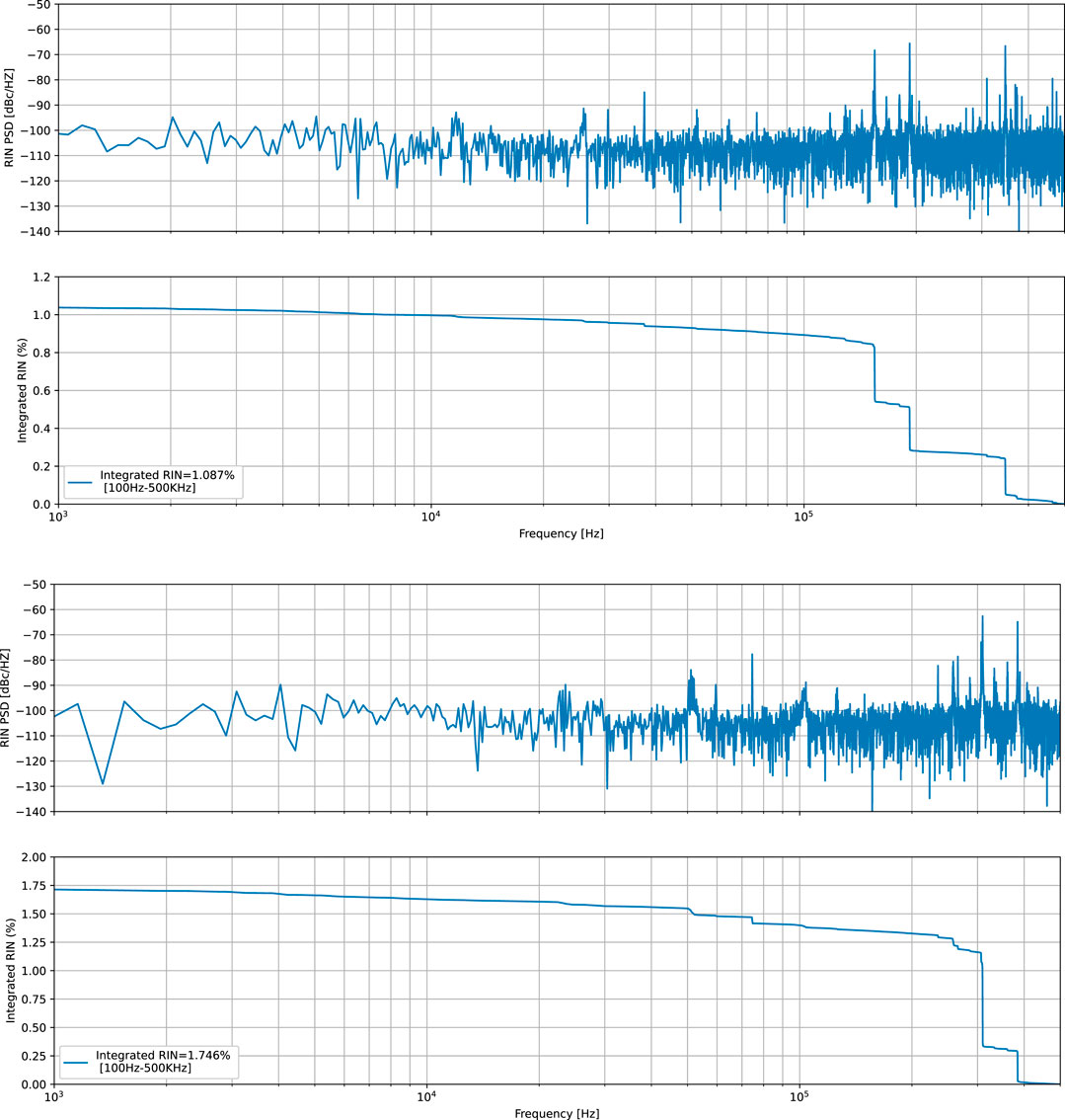
The photoinjector laser system of Shenzhen Superconducting Soft X-Ray Free Electron Laser (S3FEL) is reported in this paper. This laser system operates at up to 1 MHz and produces more than 50 μJ infrared (IR) laser pulses. With a customized fourth harmonic generation (FHG) module, more than 2 μJ ultraviolet (UV) laser pulses were obtained. The power standard deviations of the IR laser and the UV laser are 0.093% and 0.395% respectively. While the pulse energy standard deviations are 1.087% and 1.746% correspondingly. We implemented the pulse stacking scheme to generate flat-top pulses. With four birefringent uniaxial crystals, the Gaussian pulses were converted to flat-top shape, featuring 10 ps pulse width and 0.5 ps rising and falling edges. A cut-Gaussian transverse profile with very sharp rising and falling edges can be produced after the spatial pulse shaper.
1 Introduction
S3FEL is a CW free electron laser facility in plan phase. This high repetition rate soft-X-ray super-conducting free-electron laser facility consists of a 2.5 GeV CW superconducting linear accelerator and four initial undulator lines, which aims at generating X-Rays between 40 eV and 1 keV at rates up to 1 MHz. Photoinjectors are often exploited as the initial electron source for many FEL facilities, like for instance FLASH [1], SPARC [2], LCLS [3], LCLS-II [4], SwissFEL [5], FERMI [6], SHINE [7] and European XFEL [8]. Photoinjector is a device that produces high-quality electron beams by using drive laser to extract electrons from the cathode material. The basic properties of the electron beams, such as the stability of the produced charge and the emittance of the electron beams, are influenced by the pulse parameters of the drive laser [9]. Temporally and spatially shaping of the laser pulses should be performed in order to obtain minimal increase of transverse emittance at acceleration of electron beams [10–13]. The photoinjector laser system is a very crucial part and has a significant impact on performances of FELs. In this paper, we describe the S3FEL photoinjector laser system, including the IR front end laser, UV conversion unit and temporal-spatial pulse shaping unit. In order to be operating at a high repetition rate (adjustable up to 1 MHz), Cs2Te photocathode will be used to produce the initial electron bunches because of high quantum efficiency
2 Performance of the laser system
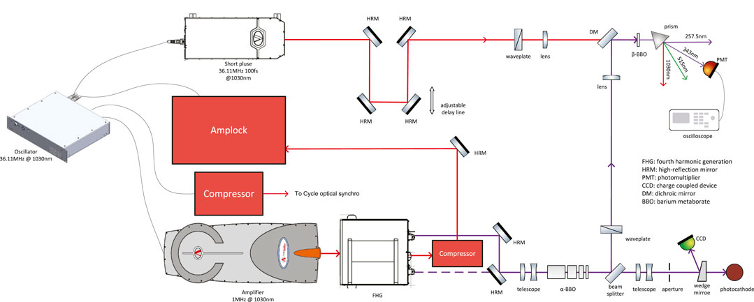
The layout of the photoinjector laser system is presented in Figure 1. The laser system consists of oscillator, short pulse module (to cross-correlator), compressor (to Cycle optical synchro module), slow drift locking module (Amplock), IR fiber amplifier, FHG module, temporal and spatial pulse shapers and the corresponding diagnostics setup.
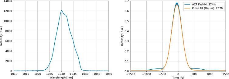
The oscillator is a customized ytterbium-doped fiber laser operating at 36.11 MHz, which has four output ports. One port serves as the seed of the IR fiber amplifier, the second one is compressed to transform-limited pulse and ready for optical-to-optical locking. The third one and the output from the IR fiber amplifier are launched to the Amplock for slow drift compensation. The fourth one is nonlinearly amplified and compressed down to sub-100 fs, so that it could increase measurement resolution of UV laser pulse duration. The oscillator is phase-locked to a 216.66 MHz RF reference signal (6th harmonic of the 36.11 MHz). The integrated timing jitter is 122 fs in the range between 10 and 10 MHz (measured by Keysight E5052B SSA @4188.76 MHz). While the oscillator is free running, the integrated timing jitter is 558 fs in the range between 10 and 10 MHz. In the future, the oscillator will be phase-locked to an optical synchro module via two-color balanced optical cross-correlation (TCBOC). The short pulse module featuring 100 mw output power and 100 fs pulse width is exploited to measure temporal pulse shape of the UV laser via optical cross-correlation. The Amplock module is used to control the timing drift between the amplifier and the oscillator via optical cross-correlation. The standard deviation of the timing drift is 13.49 fs over 8 h. The IR fiber amplifier is comprised of fiber stretcher, fiber preamplifier, pulse picker, programmable spectral phase and amplitude shaper, fiber amplifier (tangerine). The IR front-end can produce 50 μJ, 1030 nm laser pulses with adjustable repetition rate up to 1 MHz and adjustable pulse duration from 267 fs to 10 ps by changing the compression grating pair distance. Spectrum (measured by Ocean Optics HR4000) and minimal pulse width (measured by APE PulseCheck 150) of the IR laser beam are shown in Figure 2. Spectral width (FWHM) is approximately 7.5 nm and minimal pulse width is about 267 fs. The angular deviation of the IR laser beam, in the horizontal and vertical direction, were measured to be 8.62 μrad and 5.45 μrad, respectively. The IR laser beam quality factor, M square (M2), is less than 1.2 (measured by Dataray S-WCD-LCM-UV, Dataray, America) and spot ellipticity is 94%.
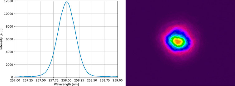
The IR laser beam directly accesses the FHG module, as presented in Figure 1. For efficient IR to UV conversion, two second harmonic generation (SHG) stages are exploited to convert 1030 nm laser to 515 nm and further to 257.5 nm. The overall conversion efficiency is strongly dependent on the laser beam diameter and the thickness of nonlinear crystals. For higher UV conversion efficiency, smaller beam diameter and thicker nonlinear crystal can be exploited. But this will deteriorate the UV laser beam quality and result in narrower spectrum. Meanwhile, high UV power would reduce the FHG nonlinear crystal lifetime owing to two-photon absorption. According to the design specifications, around 2 W UV laser is sufficient for the S3FEL. So we take a tradeoff between the UV conversion efficiency and UV beam quality/crystal damage. The first SHG is achieved via a beta barium borate (β-BBO) crystal with 2.5 mm thickness. In the second SHG, a thinner β-BBO crystal with 0.5 mm thickness is employed, which would reduce thermal load of the FHG nonlinear crystal. When the IR laser is fully compressed (shown in Figure 2) by changing the distance of compression gratings, the conversion efficiencies of the two SHG stages are around 55% and 8%, respectively. The nonlinear crystals are placed in a closed chamber with a filtered air circulation system to extend nonlinear crystals lifetime. The spectrum (spectrometer customized from Ocean Optics with 0.02 nm resolution) and beam profile (measured by ophir SP920) of the UV laser beam (operating at 1 MHz) are shown in Figure 3. Spectral width (FWHM) of the UV laser is approximately 0.4 nm which can support 245 fs transform limited laser pulse. There is no significant deterioration in the transverse beam profile due to thinner FHG nonlinear crystal. The beam profile can be preserved for approximately 3 weeks for 24/7 operation. Over time, scattering spots would be observed around the beam spot. The UV laser pulse energy would drop by approximately 20% when the repetition rate is adjusted from 1 MHz to 1 KHz due to less thermal load. One microjoule is enough for our application. There is a energy attenuator consisting of a half waveplate and a polarizer before the electron gun. The laser energy on the photocathode can remain constant by adjusting the attenuator when the repetition rate changes.
2.1 Power stability and pulse energy stability
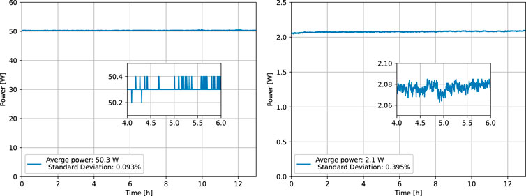
In order to measure the power stability of the IR laser and the UV laser, output powers of the IR front-end and the FHG module were directly measured (Gentec UP25N-100H-H9-D0) over 12 h, respectively. The measured results are presented in Figure 4. The average output power of the IR laser is approximately 50 W (at 1 MHz) and standard deviation is approximately 0.093% over 12h, as shown in Figure 4 (left). When the power of the IR laser is set to 45 W by rotating the half wave plate inside the FHG module, the average power of the UV laser is approximately 2.1 W and standard deviation is approximately 0.395%, as shown in Figure 4 (right). The overall conversion efficiency from IR laser to UV laser is about 4.67%.
Pulse energy stability of drive laser is also very important for FELs because electron beam parameters are affected by drive laser pulse energy. A photodetector (Thorlabs DET10A2), featuring 350 MHz bandwidth and 200nm–1100 nm wavelength, was used to receive the IR laser or the UV laser. An oscilloscope (Keysight Infiniium MXR404A), featuring 16GSa/s sampling rate and 200Mpts memory depth, was exploited to measure the voltage signal from the photodetector. The capture time of the oscilloscope is 12.5 ms (200Mpts/16GSa/s), which means 12,500 laser pulses (@1 MHz) can be recorded one time. The pulse energy of every laser pulse can be obtained by taking peak values of the measured voltage signal. Relative intensity noise power spectral density (RIN PSD) of pulse energy can be obtained via scipy.signal.periodogram function [18]. Relative intensity noise can be obtained by integrating the RIN PSD [19], the results are presented in Figure 5. From Figure 5 (top), we can know that the integrated RIN of the IR laser from 100 Hz to 500 KHz is 1.087% and the RIN is mainly distributed in the 100 KHz–400 KHz domain. This intensity noise should come from the oscillator because the PSD changes when another oscillator is used. Relaxation oscillation and pump power fluctuation of the oscillator may mainly contribute to the noise in this frequency range [20]. The integrated RIN of the UV laser from 100Hz to 500 KHz is 1.746%, which is almost twice of the IR laser. The RIN of the UV laser is mainly distributed in the 300 KHz–400 KHz domain, as shown in Figure 5 (bottom). When the overall conversion efficiency from IR laser to UV laser reaches 8%, the integrated RIN of the UV laser would be reduced to 1.112% due to the saturation effect of nonlinear processes. But this would deteriorate the UV laser beam quality and reduce FHG nonlinear crystal lifetime. In the future, the FHG module will be redesigned and an acousto-optic modulator (AOM) will be introduced between the two SHG nonlinear crystals to suppress the RIN of the UV laser. The AOM also acts as the fast optical shutter to protect the FEL facility when a failure occurs.
2.2 Temporal shaping
Temporal shaping of the laser involves controlling the duration and temporal profile of the laser pulses, which is important for optimizing the electron beam properties and FEL performance. In this work, we employed the typical pulse stacking for temporal shaping. Pulse stacking is a technique used to generate laser pulses with a flat-top temporal profile. This is achieved by splitting the amplified pulses into sub-pulses, delaying each sub-pulse by a controlled amount, and then recombining them to create a train of pulses with a uniform flat-top profile [21]. As shown in Figure 1, the temporal pulse shaper consists of four alpha-barium borate (α-BBO) crystals (with thickness 11.58, 5.79, 2.90, and 1.45 mm) which have large birefringence over a broad transparent range of 190–3500 nm. These crystals are cut with their optical axes parallel to their optical surfaces and anti-reflection coated at 257.7 nm. The transmission efficiency of the pulse shaper is approximately 64% owing to the linear and nonlinear absorption. The group refractive index for o-wave and e-wave is ngo = 2.071 and nge = 1.823 @257.5 nm [22, 23]. So, the group velocity mismatch (GVM) is 0.846 ps/mm. The temporal intensity distribution of the UV laser is measured via optical cross-correlation, as shown in Figure 1. A β-BBO crystal with 0.1 mm thickness is used as the nonlinear crystal to generate differential frequency signal (343 nm) and a PMT is used to receive the signal. A python program was developed to control the delay line (one step 3 μm) and read signal from the PMT. The temporal intensity of the UV laser can be obtained from the recorded positions of the delay line and the signals from the PMT. The temporal intensity distribution of the incident UV laser pulse is presented in Figure 6 (left), the pulse width is approximately 1 ps. The pulse shape is not perfect Gaussian, possibly due to the presence of second-order and higher-order dispersion. After the temporal pulse shaper, a nearly flat-top laser pulse with 10ps pulse width can be obtained, as shown in Figure 6 (right).
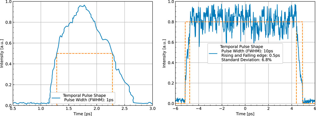
FIGURE 6. Temporal intensity distribution of the incident laser (left) and the output laser (right).
2.3 Spatial shaping
Spatial shaping of the UV pulses involves controlling the intensity profile of the laser beam in the transverse plane, which is important for generating a uniform electron beam. The 257.5 nm DUV laser used in the S3FEL photoinjector incorporates a pinhole that used to generate apodized beam by the so called hard-cut method. The pinhole would be imaged onto the photocathode via the image relay system. This ensures that the laser beam has a uniform intensity distribution across the photocathode. A camera placed in the equivalent position to the photocathode plane can be used to monitor laser beam position and spatial distribution on the photocathode. The resulted laser beam profile recorded by the camera is presented in Figure 7. The laser beam has very sharp rising edge and falling edge which would improve the electron beam emittance. The position of the pinhole can be adjusted to ensure its image is exactly on the photocathode.
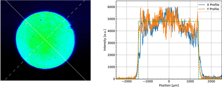
FIGURE 7. Laser beam transverse profile (left) and XY direction profile (right) after the spatial pulse shaper.
3 Conclusion
The photoinjector laser system for S3FEL was established and tested. The main amplifier delivers 1 MHz, 50 uJ IR laser pulses and is tightly synchronized with RF reference and ready for locking with optical reference. With fourth harmonic generation, we generate the 257.5 nm UV laser with more than 2 W average power and good long-term performance. By pulse stacking and apodization method, we generate flat-top beam both in time and spatial domain. In the future, for longer UV temporal shaping (
Data availability statement
The raw data supporting the conclusion of this article will be made available by the authors, without undue reservation.
Author contributions
All authors listed have made a substantial, direct, and intellectual contribution to the manuscript and approved it for publication.
Funding
This work is supported by the National Natural Science Foundation of China (12175324) and Shenzhen Commission of Development and Reform Research funding (ZDKJ20200106001).
Conflict of interest
The authors declare that the research was conducted in the absence of any commercial or financial relationships that could be construed as a potential conflict of interest.
Publisher’s note
All claims expressed in this article are solely those of the authors and do not necessarily represent those of their affiliated organizations, or those of the publisher, the editors and the reviewers. Any product that may be evaluated in this article, or claim that may be made by its manufacturer, is not guaranteed or endorsed by the publisher.
References
1. Ackermann W, Asova G, Ayvazyan V, Azima A, Baboi N, Bähr JW, et al. Operation of a free-electron laser from the extreme ultraviolet to the water window. Nat Photon (2007) 1:336–42. doi:10.1038/nphoton.2007.76
2. Cianchi A, Alesini D, Bacci A, Bellaveglia M, Boni R, Boscolo M, et al. High brightness electron beam emittance evolution measurements in an rf photoinjector. Phys Rev ST Accel Beams (2008) 11:032801. doi:10.1103/PhysRevSTAB.11.032801
3. Akre R, Dowell D, Emma P, Frisch J, Gilevich S, Hays G, et al. Commissioning the linac coherent light source injector. Phys Rev ST Accel Beams (2008) 11:030703. doi:10.1103/PhysRevSTAB.11.030703
4. Gilevich S, Alverson S, Carbajo S, Droste S, Edstrom S, Fry A, et al. The LCLS-II photo-injector drive laser system. In: Conference on lasers and electro-optics. In: 2020 Conference on Lasers and Electro-Optics (CLEO); 10-15 May 2020; San Jose, CA, USA (2020).
5. Schietinger T, Pedrozzi M, Aiba M, Arsov V, Bettoni S, Beutner B, et al. Commissioning experience and beam physics measurements at the SwissFEL injector test facility. Phys Rev Accel Beams (2016) 19:100702. doi:10.1103/PhysRevAccelBeams.19.100702
6. Penco G, Allaria E, Badano L, Cinquegrana P, Craievich P, Danailov M, et al. Optimization of a high brightness photoinjector for a seeded FEL facility. J Instrumentation (2013) 8:05015. Available from. doi:10.1088/1748-0221/8/05/p05015
7. Zhao Z, Wang D, Yang Z, Yin L. SCLF: An 8-GeV CW SCRF linac-based X-ray FEL facility in shanghai. In: Proceedings, 38th International Free Electron Laser Conference, FEL2017; 20-25 August 2017; Santa Fe, NM, United States (2018).
8. Decking W, Abeghyan S, Abramian P, Abramsky A, Aguirre A, Albrecht C, et al. A MHz-repetition-rate hard X-ray free-electron laser driven by a superconducting linear accelerator. Nat Photon (2020) 14:391–7. doi:10.1038/s41566-020-0607-z
9. Zhen Z, Yuantao D, Zhirong H, Feng Z. Multiplexed photoinjector optimization for high repetition rate free electron lasers. Front Phys (2023) 11, 11. doi:10.3389/fphy.2023.1166216
10. Gacheva EI, Zelenogorskii VV, Andrianov AV, Krasilnikov M, Martyanov M, Mironov S, et al. Disk Yb:KGW amplifier of profiled pulses of laser driver for electron photoinjector. Opt express (2015) 23(8):9627–39. doi:10.1364/oe.23.009627
11. Li Y, Lewellen JW. Generating a quasiellipsoidal electron beam by 3D laser-pulse shaping. Phys Rev Lett (2008) 100:074801. doi:10.1103/PhysRevLett.100.074801
12. Bazarov IV, Ouzounov DG, Dunham BM, Belomestnykh SA, Li Y, Liu X, et al. Efficient temporal shaping of electron distributions for high-brightness photoemission electron guns. Phys Rev ST Accel Beams (2008) 11:040702. doi:10.1103/PhysRevSTAB.11.040702
13. Sheehy B. ERL R&D: Laser and laser light transport (2010). BNL-90921-2010-IR. Available from: https://www.osti.gov/biblio/1013444 (Accessed March 1, 2023).
14. Xiang R, Teichert J. Photocathodes for high brightness photo injectors. Phys Proced (2015);77:58–65. (Accessed March 1, 2023). doi:10.1016/j.phpro.2015.11.010
15. Lederer S, Hansen H, Schreiber S. Photocathodes at flash. In: 33rd International Free Electron Laser Conference; August 22-26, 2011; Shanghai, China (2016).
16. Schreiber S, Michelato P, Monaco L, Pagani C, Sertore D. Photocathode studies at flash. In: Proceedings of EPAC08; June 23 - 27, 2008; Genoa, Italy (2008).
17. Lederer S, Michelato P, Monaco L, Sertore D. Cathode issues at the flash photoinjector. In: Proceedings of FEL08; May 13-15, 2008; Gyeongju, Korea (2008).
18.Smit-create, end olith, yotarok, WarrenWeckesser, BassCoder2808. Data From: scipy.signal.periodogram (2019). Available from: https://docs.scipy.org/doc/scipy/reference/generated/scipy.signal.periodogram.html (Accessed March 1, 2023).
19. Keller U. Ultrafast lasers: A comprehensive introduction to fundamental principles with practical applications. 1st ed. Cham: Springer (2022).
21. Will I, Klemz G. Generation of flat-top picosecond pulses by coherent pulse stacking in a multicrystal birefringent filter. Opt Express (2008) 16(19):14922–37. doi:10.1364/oe.16.01492
22. Smith AV. How to select nonlinear crystals and model their performance using SNLO software. In: JW Pierce editor. International society for optics and photonics. Bellingham, Washington USA: SPIE (2000). p. 62–9. Nonlinear Materials, Devices, and Applications. doi:10.1117/12.379931
23.CASTECH. Alpha-barium borate (2002). Available from: https://www.castech.com/product/%CE%B1-BBO–-Alpha-Barium-Borate-90.html (Accessed March 1, 2023).
Keywords: FEL, high repetition, photoinjector laser, pulse shaper, power stability, energy stability
Citation: Zhang B, Li X, Liu Q, Zhu Z, Zhang W, He Z, Liu W, Wu G and Yang X (2023) High repetition-rate photoinjector laser system for S3FEL. Front. Phys. 11:1181862. doi: 10.3389/fphy.2023.1181862
Received: 08 March 2023; Accepted: 31 May 2023;
Published: 14 June 2023.
Edited by:
Nicholas Walker, Helmholtz Association of German Research Centres (HZ), GermanyReviewed by:
Feng Zhou, Stanford University, United StatesLutz Winkelmann, Helmholtz Association of German Research Centres (HZ), Germany
Copyright © 2023 Zhang, Li, Liu, Zhu, Zhang, He, Liu, Wu and Yang. This is an open-access article distributed under the terms of the Creative Commons Attribution License (CC BY). The use, distribution or reproduction in other forums is permitted, provided the original author(s) and the copyright owner(s) are credited and that the original publication in this journal is cited, in accordance with accepted academic practice. No use, distribution or reproduction is permitted which does not comply with these terms.
*Correspondence: Guorong Wu, d3VnckBkaWNwLmFjLmNu; Zhigang He, emdoZUBkaWNwLmFjLmNu; Wei Liu, bGl1d0BtYWlsLmlhc2YuYWMuY24=
†These authors have contributed equally to this work and share first authorship
 Baichao Zhang1†
 Xiaoshen Li
 Zhigang He
 Wei Liu