 Fang Hao1,2,3
 Wei Wang
- 1College of Intelligent Systems Science and Engineering, Harbin Engineering University, Harbin, China
- 2The 54th Research Institute of China Electronics Technology Group Corporation, Shijiazhuang, China
- 3State Key Laboratory of Satellite Navigation System and Equipment Technology, Shijiazhuang, China
Fog computing has been applied to the data processing for the Internet of Things (IoT) based on distributed high-precision Global Navigation Satellite Systems (GNSS). However, the space-time adaptive processing (STAP) interference suppression technology in the system will cause fog computing data deviation that includes carrier phase bias and pseudocode offset. An unbiased STAP technique is proposed to eliminate these deviations. First, it is analyzed that the carrier phase bias and pseudocode offset are caused by the non-linear phase response of the STAP equivalent filter. Then, a coefficient-constrained method based on practical engineering processing is proposed, which can eliminate these deviations by restricting the tap coefficients to be symmetrically equal around the center-tap. Moreover, by analyzing the coherent integral function of the pseudocode after filtering, the tap structure of STAP is modified to eliminate the group offset of the pseudocode without increasing the computational complexity and hardware resources. Finally, the unbiased performance and anti-interference performance of the system are verified by numerical and real data simulations.
1 Introduction
With the development of the Internet of Things (IoT) based on 5G + new infrastructure and Beidou satellite services, fog computing has been applied to the data processing for the IoT based on distributed high-precision positioning systems, which ensures lower communication delay and higher positioning efficiency [1–3]. However, since the navigation signal is weak, the data broadcast/reception of each fog computing node is easily interfered [4, 5]. In [6, 7], space-time adaptive processing (STAP) based on the array antenna is used to solve this problem, which places a FIR filter after each array element. This filter can process more interferences in the frequency domain without increasing the array size.
Currently, many STAP techniques have been proposed. These techniques can cancel the strong power interference, but will cause distortion of the desired signal [8–11]. Simulations and experiments show that STAP may introduce errors of more than 10 m or even a hundred meters into GNSS measurement data processed by fog calculation [12, 13]. Fante el [14]. Proposed a filter with conjugate inverse of STAP filter to eliminate phase deviation. This strategy widens the cross-coherent peak of the pseudocode and consumes more hardware resources. Wu et al. [15] proposed a homomorphic filter that performs frequency domain processing on the original filter to compensate for errors. Frequency domain processing is complex and takes up more memory cells. O'Brien AJ el [16, 17]. Proposed an optimal adaptive filtering method for STAP, which can maximize the carrier to noise ratio without generating measurement bias. This method requires constructing a constraint matrix based on the incident angle and the signal power spectral density, which has high computational complexity and cannot be applied to engineering implementation. References [18–20] all constrain the filter coefficients to eliminate the carrier phase bias and pseudocode offset on the premise of ensuring the linear phase response of the FIR filter. However, the method of reference [18] cannot correct the carrier phase bias. Reference [19] does not give a closed-form solution of its method. The strategy proposed by Xu et al. [20] is a solution of [19], but requires complex operations, such as block matrix processing and multi beam forming. All these methods, due to the STAP filter structure, still have a constant pseudocode offset due to the STAP filter structure which has to be compensated in the receiver tracking loop [21]. To eliminate this constant offset, Marathe et al. [22] proposed a single-tap output strategy, which only outputs the data of the reference tap. But the system response of this method is non-linear, the carrier bias is generated.
Motivated by mentioned above, this paper proposes an unbiased STAP strategy. First, the measurement bias caused by the non-linear response of the STAP filter in the IoT system is analyzed based on distributed high-precision positioning and fog computing. Then, an anti-interference strategy that constrains the tap coefficients to be symmetrically equal about the center tap is proposed based on linear-phase FIR filter. Meanwhile, by analyzing the coherent integral function of the pseudocode, the tap structure of STAP is modified to achieve null offset of the pseudocode without increasing the computational complexity and hardware resources. Finally, the experiments are conducted and the results validate the effectiveness of the proposed schemes.
The rest of this paper is organized as follows. Section 1 discusses the array modeling and Section 3 provides the proposed unbiased anti-interference strategy. In Section 4, the algorithm performance is simulated and evaluated by various experiments and finally, Section 5 concludes this paper.
2 Related work
1) Adaptive Beamforming in IoT Scenarios
With the development of wireless network transmission technology and the introduction of intelligent IoT, the demand for anti-interference is increasing for wireless IoT application scenarios based on high-precision positioning systems such as intelligent transportation and unmanned driving. Adaptive beamforming technology (ADBF) can meet this requirement, which enhances the array receive gain while suppressing interference. Therefore, it has attracted more and more attention.
ADBF has become one of the symbols of array signal processing. Its essence is to use some optimal criterion to perform weighted filtering on the signals of each array element, which can enhance the desired signal and suppress the interference. And the weights can be adaptively updated according to the interference environment. Common guidelines are.
* Maximum Signal-to-Noise Ratio (MSNR): Maximizes the ratio of desired signal power to noise power.
* Maximum Signal to Interference and Noise Ratio (MSINR): Maximizes the ratio of desired signal power to the sum of interference power and noise power.
* Minimum Mean Squared Error (MMSE): Minimizes the mean squared error between the array output and the desired response.
* Linear Constrained Minimum Variance (LCMV): Minimizes the variance of the array output under certain constraints.
This paper improves the Capon beamformer that utilizes the LCMV criterion. The beamformer tries to minimize the power of noise and interference while keeping the signal power in the observation direction
where
2) FIR filter
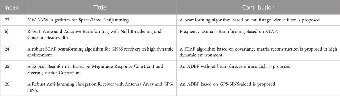
TABLE 1. The classical ADBF based LCMV schemes.
An intermediate frequency (IF) sampled data is processed based on the STAP in this paper. STAP is based on a finite impulse response (FIR) filter that is one of the crucial parts to digital signal processing. The FIR filter has two advantages of realizability and linear phase, so it is widely used in practice. Khan et al. present least squares (LS) approach to design linear phase FIR filter [27]. Wang et al. proposed new structures of type II, III and IV linear phase FIR systems [28]. In this paper, the linear phase FIR filter is used to improve the spatiotemporal two-dimensional beamformer in the wireless IoT system based on distributed high-precision positioning.
3 Array model of wireless Internet of Things systems
The structure of wireless IoT system based on distributed high-precision positioning and fog computing is shown in Figure 1. Assuming an ideal hardware environment, the mixed signal is received by an N-element linear array with half-wavelength equidistant, which can be written as
where
where
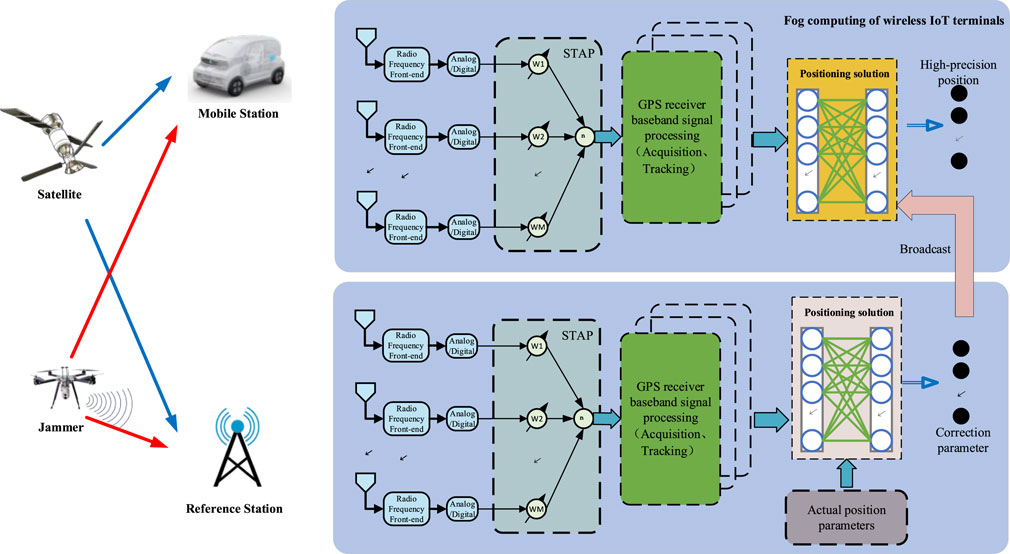
FIGURE 1. The structure of wireless IoT system based on distributed high-precision positioning and fog computing.
Assumed that each element has an M-tap FIR filter in the STAP structure, where the delay interval is
where
where
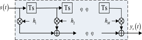
FIGURE 2. Equivalent filter structure diagram of STAP.
From Eq. (6), the estimated pseudocode phase offset is
4 The proposed STAP under wireless Internet of Things conditions
According to the analysis of measurement bias introduced by the non-linear response of STAP in Section 3, an unbiased STAP strategy is proposed. First, a filter that satisfies the linear phase response is analyzed. After that, this strategy ensures the equivalent filter linear phase response by constraining the tap coefficients to be symmetrically equal about the center tap. Finally, the STAP filter structure was modified by analyzing the coherent integral function of the pseudocode filtered by STAP. The null bias is achieved so that a generic receiver can be interfaced with the STAP processor without modifying the tracking loop. Therefore, the proposed strategy can not only suppress interference to ensure unbiased reception of signals, but also does not modify the tracking loop of generic receivers.
For a filter with a linear phase response, the frequency characteristics of the system satisfy the following relationship [29].
where
Suppose the unit impulse response of the FIR is
where
Eq. 10 performs the crossover-multiplication operations to get
Eq. 10 is a necessary condition for FIR to satisfy strictly linear phase. It is easy to know that the constraint that makes Eq. 9 hold constant for any
The above equation shows that there is a linear phase characteristic with a phase delay
where the filter coefficients are
where
First, the constraints in Eq. 13 are represented in matrix. Let
The constraints can be written as
Further, let
where
The objective function in Eq. 13 can be written as
From the above derivation, Eq. 13 can be rewritten as
It can be solved
The
Eq 24 satisfies the linear phase condition and has
where

FIGURE 3. The modified STAP equivalent filter structure.
In Figure 3, the center tap is used as the input reference, and the output of the filter is obtained by accumulating the signals of each tap. Therefore, when the filter phase response is linear, the delay deviation of the pseudocode cross-coherent peak is the same as the time delay of the center tap, i.e., its delay is 0. The cross-coherent function is
It can be clearly displayed from Eq. 10 that the position of the cross-coherent peak is
5 Results and discussion
An distributed wireless IoT system with a 4-element linear array is considered, and the satellite software simulator is used to generate the complex Beidou B1 band signal received by the 4-element linear array. The sampling frequency and time are set to 20 MHz and 1.5s, respectively. Array elements are placed equidistant with half wavelength. The complex signal of baseband IF 5.68 MHz is filtered by STAP. The number of delay nodes is 15. To test the effectiveness of the proposed strategy, the wideband continuous wave (WCW) interference and the wideband Gaussian noise (WGN) interference are added at t = 0.6s and t = 1.2s, respectively. The setting of interference scenarios is shown in Table 2.
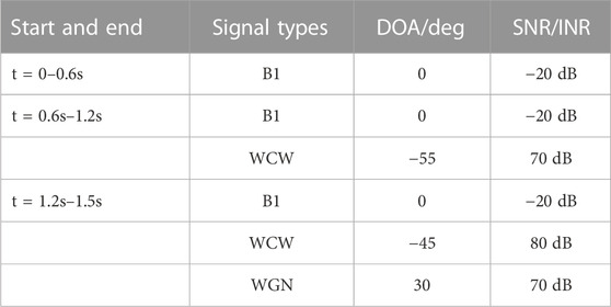
TABLE 2. Basic signal parameters.
The simulation of anti-interference null is carried out to verify the anti-interference capability in the distributed wireless IoT system. Figure 4 shows the null depth of traditional PI, Ge-MVDR method [22] and the proposed anti-interference strategy at different INRs during 600–1200 ms. The Monte Carlo experiment was performed 500 times. The anti-interference nulling of the proposed strategy is comparable to that of the Ge-MVDR method and slightly lower than that of the PI method, but it can still meet the required interference suppression.
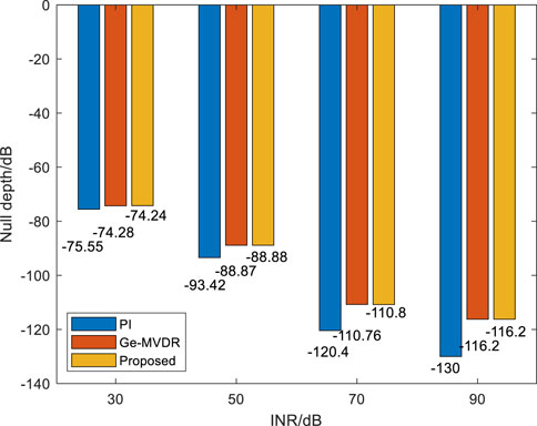
FIGURE 4. The null depth of three strategies at different INRs.
Then, the baseband synchronization is performed by using an open-access software receiver [30]. To highlight the effectiveness of the algorithm, the PI method, the Ge-MVDR method and conjugate constraint (CC) method [19] are compared. Obviously, the tracking of the PI strategy and the Ge-MVDR strategy have errors as the scene changes in Figures 5, 6. At 600 ms and 1,200 ms, the carrier phase bias of the PI method is about 8° and 80°, and the carrier phase bias of the Ge-MVDR method is about 5° and 9°. In addition, after 600 ms, the pseudocode phase offset of the PI and Ge-MVDR is about 0.087 chips and 0.098 chips, and after 1,200 ms, the pseudocode phase offset of the PI and Ge-MVDR is about 0.17 chips and 0.1 chips. On the contrary, the CC method and the proposed strategy have no error, but the code phase of the CC method still has a constant delay bias
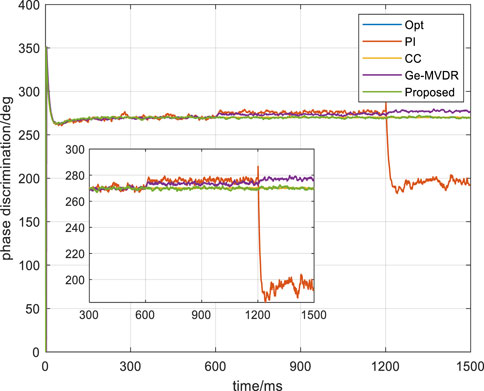
FIGURE 5. The carrier tracking diagram.
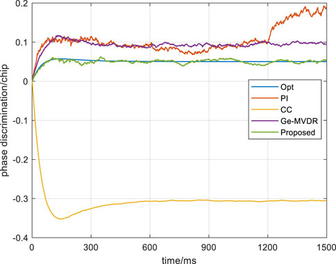
FIGURE 6. The pseudocode tracking diagram.
For the residual error after applying the proposed strategy in the distributed wireless IoT system, the carrier phase and pseudocode phase are compared with the optimal value. Optimal values are generated in the environment without interference and noise. Figure 7 is a carrier phase comparison diagram. The carrier phase fluctuation range of the proposed strategy is ± 2.5°. The error of the carrier phase is within 0.14 cm. Figure 8 is a pseudocode phase comparison diagram. The fluctuation range of the pseudocode phase error is ±0.012 chips, that is, the error is within 3.517 m. These residuals are affected by noise, and can be further eliminated by smoothing the multiple positioning results.
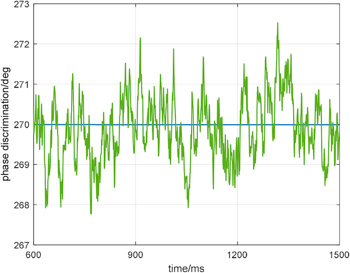
FIGURE 7. The carrier phase comparison diagram.
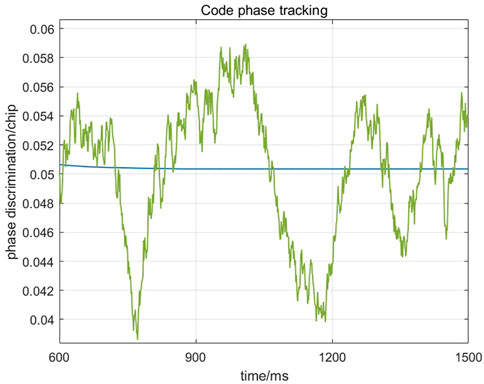
FIGURE 8. The pseudocode phase comparison diagram.
To verify the high-precision positioning of the distributed wireless IoT system based on fog computing, the actual satellite signal and three interferences were received, as shown in Figure 9. HG-SOFTGPS02 GNSS intermediate frequency signal collector is utilized. The sampling frequency is 16.369MHz, and the IF is 4.1304 MHz. It is assumed that the reference station and the mobile station have achieved precise positioning in an interference-free environment, i.e., the positioning result is the true position. The calculation formula of the pseudo-range is
where r is the actual star-ground geometric distance,
where
where
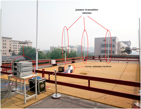
FIGURE 9. Experimental scene diagram.
For pseudo-range differential positioning, the accurate measurement information of the reference station is used to broadcast the correction parameters to the mobile station, which can eliminate the satellite clock error, receiver clock error and noise components of the mobile station to achieve accurate measurement. To verify the effect of pseudocode phase deviation on high-precision positioning, it is sufficient to add the distance corresponding to the pseudocode phase deviation to the accurate measurement information. Figure 10 shows the results of pseudo-range differential positioning. The positioning error of east, north and altitude are less than 1 m.
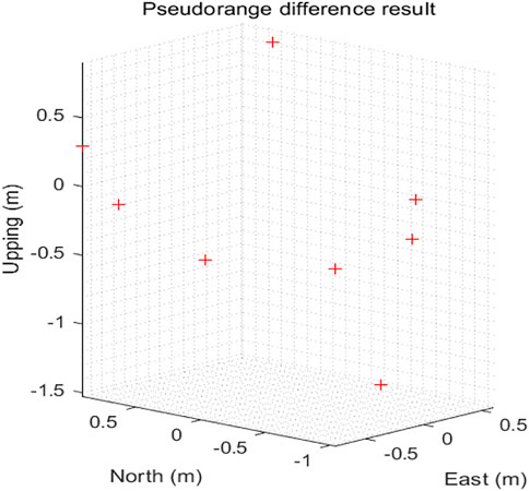
FIGURE 10. Pseudo-range differential positioning result diagram.
Similarly, for the effect of carrier phase deviation on high-precision positioning, it is only necessary to add the distance corresponding to the carrier phase measurement deviation to the accurate measurement information. Figure 11 shows a plot of the carrier phase differential positioning results. The positioning error of east, north and altitude are less than 10 cm. Figure 12 is the constellation diagram of the acquired satellite signals.
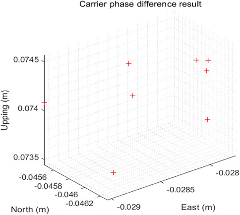
FIGURE 11. Plot of carrier phase differential positioning results.
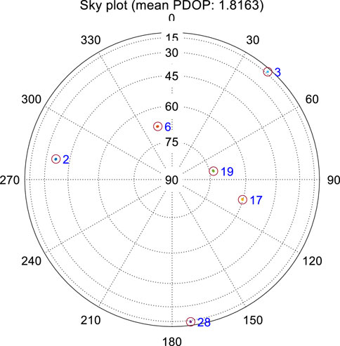
FIGURE 12. The acquired satellite constellation map.
6 Conclusion
To ensure that the navigation data is accurate and not interfered during broadcast/reception of each fog computing node in the distributed wireless IoT system based on high-precision positioning, an unbiased STAP anti-interference strategy is proposed in this paper. By reconstructing the equivalent filter structure and constraining the filter coefficients, this proposed strategy eliminates pseudocode shift and carrier phase bias due to the non-linear response of STAP systems, which can effectively improve the anti-interference performance and high-precision positioning capabilities of wireless IoT such as the Internet of Vehicles, intelligent logistics and disaster warning. The experiment results state that the error result of pseudo-range differential positioning is less than 1m, and the error result of carrier phase differential positioning is less than 10 cm.
Data availability statement
The datasets presented in this article are not readily available because There is a foundation for long-term project cooperation between us. Requests to access the datasets should be directed to FH, hf791350398@163.com.
Author contributions
Conceptualization, FH and WW; Methodology, FH, XL, and WW; Software, FH Validation, FH, WW, and JZ, Formal analysis, FH and XL; Writing—original draft preparation, FH Writing—review and editing, FH, WW, XL, and JZ
Funding
This work is supported in part by the Fundamental Research Funds for the Central Universities (3072022QBZ0401, 3072021CFT0404), and it is also supported by Key-Area Research and Development Program of Guangdong Province. (Grant No. 902180320175).
Conflict of interest
The authors declare that the research was conducted in the absence of any commercial or financial relationships that could be construed as a potential conflict of interest.
Publisher’s note
All claims expressed in this article are solely those of the authors and do not necessarily represent those of their affiliated organizations, or those of the publisher, the editors and the reviewers. Any product that may be evaluated in this article, or claim that may be made by its manufacturer, is not guaranteed or endorsed by the publisher.
References
1. Wang L, Li L, Qiu R. Edge computing-based differential positioning method for BeiDou navigation satellite system. KSII Trans Internet Inf Syst (2019) 13:69–85. doi:10.3837/tiis.2019.01.005
2. Zhang PY, Wang YQ, Kumar N, Jiang CX, Shi GW. A security and privacy-preserving approach based on data disturbance for collaborative edge computing in social IoT systems. IEEE Trans Comput Soc Syst (2022) 9:97–108. doi:10.1109/TCSS.2021.3092746
3. Zhang PY, Jiang CX, Pang X, Qian Y. STEC-IoT: A security tactic by virtualizing edge computing on IoT. IEEE Internet Things J (2021) 8:2459–67. doi:10.1109/jiot.2020.3017742
4. Ni SJ, Ren BB, Chen FQ, Lu ZK, Wang J, Ma PC, et al. GNSS spoofing suppression based on multi-satellite and multi-channel array processing. Front Phys (2022) 10:10. doi:10.3389/fphy.2022.905918
5. Ren BB, Chen FQ, Ni SJ, Han C, Lu Z, Han S. Performance analysis of repeater spoofing suppression based on GNSS multi-beam receiver. Front Phys (2022) 10:10. doi:10.3389/fphy.2022.970132
6. Yang X, Li S, Sun Y, Long T, Sarkar TK. Robust wideband adaptive beamforming with null broadening and constant beamwidth. IEEE Trans Antennas Propagation (2019) 67:5380–9. doi:10.1109/TAP.2019.2916607
7. Wang H, Yao Z, Fan Z, Yang J, Liu G. A robust STAP beamforming algorithm for GNSS receivers in high dynamic environment. Signal Process. (2020) 172:107532–10. doi:10.1016/j.sigpro.2020.107532
8. Church C, Gupta I, O'Brien A. Adaptive antenna induced biases in GNSS receivers. In: Proceedings of the 63rd Annual Meeting of The Institute of Navigation; -25 April 2007; Cambridge, Massachusetts (2007). p. 204–12.
9. Chuang YC, Gupta IJ. Antenna induced biases in GNSS receiver measurements. In: Proceedings of the 2013 International Technical Meeting of The Institute of Navigation; January 29 - 27, 2013; San Diego, California (2013). p. 164–71.
10. Lee K, So H, Song K. Performance analysis of pseudorange error in STAP beamforming algorithm for array antenna. J Positioning, Navigation, Timing (2014) 3:37–44. doi:10.11003/JPNT.2014.3.2.037
11. Daneshmand S, Jahromi AJ, Broumandan A, Lachapelle G. GNSS space-time interference mitigation: Advantages and challenges. In: Proceedings of the International Symposium on GNSS (IS-GNSS '15); July 7 and 8, 2015; Darmstadt, Germany (2015). p. 11.
12. Daneshmand S, Jahromi AJ, Broumandan A, Lachapelle G. GNSS space-time interference mitigation and attitude determination in the presence of interference signals. Sensors (2015) 15:12180–204. doi:10.3390/s150612180
13. Vagle N, Broumandan A, Jafarnia A. Characterization of GNSS measurement distortions due to antenna array processing in the presence of interference signals. In: 2014 Ubiquitous Positioning Indoor Navigation and Location Based Service (UPINLBS); November 20-21,2014; TX, USA (2014). p. 71–80.
14. Fante RL, Vaccaro JJ. Wideband cancellation of interference in a GPS receive array. IEEE Trans Aerospace Electron Syst (2000) 36:549–64. doi:10.1109/7.845241
15. Wu R, Xu R, Lu D. STAP compensation technique based on homomorphic filtering in GPS. In: 2010 IEEE International Symposium on Phased Array Systems and Technology; October 12–15, 2010; Boston (2010). p. 841–5.
16. O'Brien AJ, Gupta IJ. An optimal adaptive filtering algorithm with zero antenna-induced bias for GNSS antenna arrays. Navigation (2010) 57(2):87–100. doi:10.1002/j.2161-4296.2010.tb01769.x
17. O'Brien AJ, Gupta IJ. Mitigation of adaptive antenna induced bias errors in GNSS receivers. IEEE Trans Aerospace Electron Syst (2011) 47(1):524–38. doi:10.1109/TAES.2011.5705689
18. Wang Y, Liu W, Huang L, Xiao Z, Wang F. Distortionless pseudo-code tracking space–time adaptive processor based on the PI criterion for GNSS receiver. IET Radar, Sonar and Navigation (2020) 14:1984–90. doi:10.1049/iet-rsn.2020.0189
19. Chen F, Nie J, Li B, Wang F. Distortionless space-time adaptive processor for global navigation satellite system receiver. IEEE Elect Lett (2015) 51:2138–9. doi:10.1049/el.2015.2832
20. Xu H, Cui X, Lu M. Adaptive blind nulling without measurement biases in GNSS receivers. In: 2017 IEEE 17th International Conference on Communication Technology (ICCT); 27-30 October 2017; Chengdu, China (2017). p. 1074–8.
21. Dai X, Nie J, Chen F, Ou G. Distortionless space-time adaptive processor based on MVDR beamformer for GNSS receiver. IET Radar Sonar Navigat (2017) 11:1488–94. doi:10.1049/iet-rsn.2017.0168
22. Marathe T, Daneshmand S, Lachapelle G. Assessment of measurement distortions in GNSS antenna array space-time processing. Int J Antennas Propagation (2016) 2016:1–17. doi:10.1155/2016/2154763
23. Liu F, Zhang M, Gao F. MWF-NW algorithm for space-time antijamming. Prog Electromagnetics Res M (2019) 78:165–74. doi:10.2528/PIERM18120504
24. Wang H, Yao Z, Fan Z, Yang J, Liu G. A robust STAP beamforming algorithm for GNSS receivers in high dynamic environment. Signal Processing (2020) 6:107532–. doi:10.1016/j.sigpro.2020.107532
25. Wang X, Xu D, Wang W, Han Z. Robust beamformer based on magnitude response constraint and steering vector correction. Elect Lett (2015) 51:1302–4. doi:10.1049/el.2015.0968
26. Li Q, Wang W, Xu D, Wang X. A robust anti-jamming navigation receiver with antenna array and GPS/SINS. IEEE Commun Lett (2014) 18:467–70. doi:10.1109/LCOMM.2014.012314.132451
27. Khan M, Agha S. Least squares linear phase FIR filter design and its VLSI implementation. Analog Integrated Circuits Signal Process. (2020) 105:99–109. doi:10.1007/s10470-020-01688-9
28. Wang PH, Yu BY, Chen PN. Type II, III, and IV linear-phase FIR structures based on cardinal filters. IEEE Trans Circuits Syst Express Briefs (2019) 66:1920–4. doi:10.1109/TCSII.2019.2892484
29. Richard G. Understanding digital signal processing. Upper Saddle River, New Jersey, USA: Prentice Hall PTR (2010).
Keywords: Internet of Things, STAP, high-precision, anti-interference, fog computing, GNSS
Citation: Hao F, Li X, Wang W and Zhao J (2023) A STAP anti-interference technology with zero phase bias in wireless IoT systems based on high-precision positioning. Front. Phys. 11:1179615. doi: 10.3389/fphy.2023.1179615
Received: 04 March 2023; Accepted: 27 March 2023;
Published: 06 April 2023.
Edited by:
Junsheng Mu, Beijing University of Posts and Telecommunications (BUPT), ChinaReviewed by:
Mandeep Singh, National Institute of Technology, Karnataka, IndiaHua Wang, Beijing Institute of Technology, China
Copyright © 2023 Hao, Li, Wang and Zhao. This is an open-access article distributed under the terms of the Creative Commons Attribution License (CC BY). The use, distribution or reproduction in other forums is permitted, provided the original author(s) and the copyright owner(s) are credited and that the original publication in this journal is cited, in accordance with accepted academic practice. No use, distribution or reproduction is permitted which does not comply with these terms.
*Correspondence: Wei Wang, wangwei407@hrbeu.edu.cn