- 1College of Architecture and Civil Engineering, Xinyang Normal University, Xinyang, China
- 2College of Intelligent Construction, Wuchang University of Technology, Wuhan, China
- 3Henan International Joint Laboratory of Structural Mechanics and Computational Simulation, Huanghuai University, Zhumadian, China
- 4School of Architecture and Civil Engineering, Huanghuai University, Zhumadian, China
An efficient method of moments (MoM) based on polynomial chaos expansion (PCE) is applied to quickly calculate the electromagnetic scattering problems. The triangle basic functions are used to discretize the surface integral equations. The polynomial chaos expansion is utilized to accelerate the MoM by constructing a surrogate model for univariate and bivariate analysis. The mathematical expressions of the surrogate model for the radar cross-section (RCS) are established by considering uncertain parameters such as bistatic angle, incident frequency, and dielectric constant. By using the example of a scattering cylinder with analytical solution, it is verified that the MoM accelerated by PCE presents a considerable advantage in computational expense and speed.
1 Introduction
In recent decades, the research of electromagnetic scattering is playing a crucial role in the stealth system of military structures [1, 2], exploration of underground resources and stratum structures, target recognition, antenna radiation, electromagnetic compatibility, etc. Higher target detection ability and lower detection risk are currently considered important indicators for its design [3], manufacture, and inspection. Research on electromagnetic scattering analysis [4], especially theoretical calculation, practical testing, and uncertainty analysis of radar cross-section (RCS), is the focus of the current research [5, 6]. The RCS is a scalar quantity representing the scattering ability of the target to the incident electromagnetic wave, which can be regarded as the virtual area of the measured object. It plays a vital role in the whole life cycle of equipment design, production, testing, inspection, and use. The theoretical calculation has a lower research cost than the experimental test method.
In the field of electromagnetic scattering analysis, the differential equation methods mainly include the finite element method [7] and finite difference time domain method [8]. These methods require meshing within the domain, which leads to mesh truncation error and mesh dispersion error, which are large. Moreover, it is difficult to accurately fit the complex target surface. In addition, high-frequency methods such as graphical electromagnetic computing (GRECO) [9, 10], method of geometrical optics (GO), geometrical theory of diffraction (GTD), physical optics (PO), physical theory of diffraction (PTD), uniform theory of diffraction (UTD) [11], and the bouncing ray method (SBR) [12] are widely used to analyze the electromagnetic scattering characteristics of various complex targets due to their advantages of fast calculation speed and low memory requirement. However, the disadvantage of high-frequency methods is the lower accuracy of the calculation results [13]. The method of moments (MoM) [14–19], using integral equations, has the advantages of automatically satisfying the boundary conditions, relatively few unknowns, and high calculation accuracy. Therefore, it is widely adopted in piezoelectric materials [20], dynamics [21], and acoustics [22–24]. However, the traditional MoM needs to solve huge matrix systems [25–28], which requires a large amount of calculation and memory [29]. Considering the limitations of the aforementioned methods in rapidly solving the RCS of arbitrary targets, the polynomial chaos expansion method with model universality is adopted. According to statistical correlation, a high-precision surrogate model is established with a small number of samples, which can be used to replace the accurate analysis model with high consumption of computing resources to approximate the output results, which can significantly improve the research efficiency.
The polynomial chaos expansion with strong mathematical support was originally proposed by Wiener to construct turbulence computational models [30]. It offers a robust framework for uncertainty quantification of complex engineering problems with its mathematical elegance and global convergence behavior. The method uses basis orthogonal polynomials to expand the uncertain variable and transfers the random characteristics of the variable to polynomial coefficients through the properties of orthogonal polynomials [31]. The polynomial chaos expansion method has the advantages of constructing surrogate models with high accuracy, computing system responses efficiently, and handling systems with cross-terms effectively. It has been widely used in different engineering fields, such as heat conduction [32], structural mechanics [33, 34], fluid mechanics [35], environmental and acoustic fields [36, 37], electrical properties of nanomaterials [38], flexoelectric materials [39], and stochastic difference equations [40].
In summary, a series of research results and relatively formed mature method have been developed in the field of electromagnetic scattering analysis. However, the accuracy and efficiency of these numerical methods are difficult to be balanced in the problems with the complex model due to the large computational matrix. In this paper, the PCE is applied to accelerate the electromagnetic scattering calculation by constructing surrogate models using a small number of samples. These samples are accurately obtained by the MoM. The main novelties of this paper are as follows:
1. The surrogate model of the RCS is established using PCE based on the MoM, which achieves high precision and high-efficiency calculation.
2. Univariate and multivariate analysis of the RCS are carried out considering several different parameters.
The rest of the paper is organized as follows. Section 2 provides the computational expression of the RCS. The MoM is introduced in Section 3 to solve the unknown scattering field. Section 4 includes the PCE method and the specific orthogonal polynomials. The accuracy and efficiency of the proposed method are verified by numerical examples in Section 5, followed by the conclusion in Section 6.
2 Objective function description
In this paper, a perfect electric conductor (PEC) or dielectric conductor (DIE) in the infinite domain is considered for electromagnetic scattering analysis as shown in Figure 1.

FIGURE 1. Diagram of the electromagnetic scattering. (A) Two regions Rι: R0 is an unbounded domain in which the free space parameters are assigned (μ0, ɛ0); Γ denotes the boundary of R1. On each of its interfaces, the normal vector
The RCS is an important quantity in electromagnetism to quantify how detectable an object is to a radar signal in a given direction. It is a scalar quantity representing the scattering ability of an object, which can be understood as the equivalent scattering area of the target under the incident wave, and it is measured in square meters. It can be expressed as
where
The bistatic RCS depends on the location of the source and field points. The angle between the incident and the scattered wave is called the bistatic angle θsca. In Figure 2, the bigger brown ball denotes the source point and the smaller black point represents the field point. It can be seen that forward scattering is denoted by θsca = π and θsca = 0 denotes backscattering.
3 MOM for the electromagnetic scattering problems
In this section, we first investigate scattering problems in the context of two-dimensional structures. The MoM is used to calculate the electromagnetic field required for the RCS.
3.1 Surface integral equations
We consider a PEC cylinder with the section contour Γ of arbitrary shape impinged by a TM- or TE-polarized plane wave as illustrated in Figure 3.
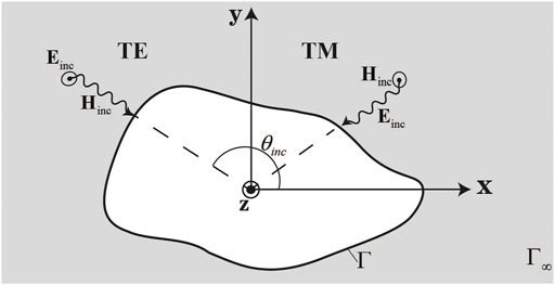
FIGURE 3. Diagram of TE- and TM-polarized field: TE-polarized electric field only has a z component and TM-polarized electric field has x and y components.
We first assume a PEC domain R1 with connected boundary Γ residing within an unbounded domain R0 with permittivity and permeability given by the scalar quantities ɛ0 and μ0, respectively. We further assume a polarized time-harmonic electromagnetic plane wave Einc of angular frequency ω, which is imposed on the PEC body with a wavenumber
where Jι and Mι denote the electric and magnetic current in Rι, respectively, and
where
Equations 3, 4 are called the electric field integral equation (EFIE) and the magnetic field integral equation (MFIE), respectively, yielding a result free of spurious solutions for DIEs. However, on closed conductors, the EFIE and MFIE cannot produce a unique solution for all frequencies, which is called the interior resonance problem. The most popular method for handling the problem is a linear combination of the EFIE and MFIE, which yields the combined field integral equation (CFIE) given by Eq. 7.
where
3.2 Discretization of MoM
The MoM is used to convert Eqs 3, 4 into a matrix system using Galerkin-type testing in each region. Expanding the electric and magnetic currents in Rι using a sum of weighted basis functions yields
where N is the number of electric and magnetic basis functions in Rl, and the basic functions fn and gn are triangle functions. We next test the EFIE and nMFIE with the electric testing functions fm, and the MFIE with the magnetic testing functions gm. This yields the matrix system in Rι as follows:
where
and
It should be noted that all blocks of the matrix in Eq. 9 are square with rank of N. If we now combine the previously mentioned matrix for the two regions, a block-diagonal system is obtained as
The coefficient α can be found by solving the previously mentioned system. Then, the expressions of electric and magnetic current can be obtained by substituting the obtained α in Eq. 8.
3.3 Scattering field
In the previous section, the expressions of electric and magnetic current are obtained, and we will further obtain numerical solutions for scattered fields in this section by using the 2-D near-field radiation equation as Eqs 19, 20.
where
The
4 Polynomial chaos expansion
PCE is a method to describe the uncertainty of random variables by constructing random spaces with polynomial bases. The original non-linear problem is transformed into a weighted summation of polynomials, which is actually a process of coefficient fitting. Orthogonal polynomials are often used as the orthogonal basis of the space to express the mapping between independent variables and dependent variables.
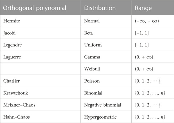
In general, different distributions of random variables lead to different orthogonal polynomials. Table 1 lists the classical families of distributions and the corresponding univariate orthogonal polynomials.
In this section, the Legendre orthogonal polynomial is adopted to construct the surrogate model of the scattered field. The uniform input variable of the system is
where Φi(x) is the multi-dimensional Legendre orthogonal polynomial with vector
where
and
where K is the number of orthogonal polynomials, which can be calculated as
The common recurrence relation of the Legendre polynomial system
For the 1-D surrogate model, Li = Φi. The truncated polynomial chaos expansion shown in Eq. 23 is actually a predicted value rather than a true solution, and the error between them is
The residual ɛ is assumed to be a zero-mean variable and α is the unknown coefficient vector. The smaller absolute value of the residual indicates the more accurate estimation of the surrogate model. The coefficient α should minimize the expectation of the sum of squares of the residual ɛ.
Thus, the polynomial chaos expansion coefficient α can be determined by the following equation.
The response from the surrogate model can be obtained with the solved coefficient α and Eq. 23. The measure used to describe the accuracy of the final model named CV (RSMD) is expressed in Eq. 30.
where yi is the output of the MoM, which is the input of PCE, and
5 Numerical examples
In this section, the output of the MoM with the cylinder model in the infinite domain is used to construct the PCE surrogate model. The univariate and bivariate analyses are adopted to verify the high accuracy and efficiency of the surrogate model. The uniform incident frequency, bistatic angle, and dielectric constant are considered the input variables. The coordinate system is established with the source point (object) as the origin, and its distance to the field point is taken as 1 × 10⁵.
The Fortran 90 language is used for MoM programming, and the non-embedded PCE programming in MATLAB is utilized to obtain the polynomial expression, and all the programs are implemented on a desktop computer with Intel (R) Core (TM) i7-8700 CPU and 16 GB RAM.
5.1 Univariate analysis
The electric and magnetic field distribution scattered by the infinite PEC cylinder with a radius of 1 is depicted in Figure 4. The results under several incident frequencies (f = 100, 500, 1000 MHz) are first considered. Figures 4A–C represent the electric field in the z-direction around the cylinder with the same level, and the magnetic field in the x-direction is shown in Figures 4D–F. It can be seen that the distribution strongly depends on the frequency and becomes more complex with increase in the incident frequency. The distribution is symmetric with respect to the x-axis, which verifies the proposed method.
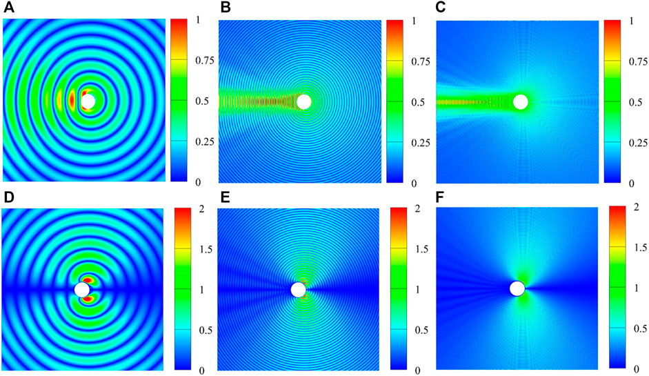
FIGURE 4. Scattering electric and magnetic field distribution under TE polarization with θsca =0. (A) Electric field, f =100MHz; (B) electric field, f =500MHz; (C) electric field, f =1000MHz; (D) magnetic field, f =100MHz; (E) magnetic field, f =500MHz; (F) magnetic field, f =1000 MHz.
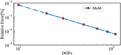
No analytical solution is proposed for most of the electromagnetic problems, especially with complex problems. It is necessary to find a rapid calculation method with high accuracy. The MoM is one of the effective numerical approaches with small errors, shown in Figure 5. The convergence result of the relative error in terms of the MoM calculation degrees of freedom (DoFs) is given in Figure 5 to verify the accuracy of the MoM. The considered DoFs range from 10 to 110. The relative error for the MoM decreases with DoF increase, and the logarithmic values present a significant linear correlation. The data computed with the MoM are considered the true value when the analytical solution does not exist. However, the CPU time consumption is huge because of the calculation of the large matrix system. On the contrary, the PCE method only needs the input data irrespective of the complexity of the problem is, which makes it more efficient.
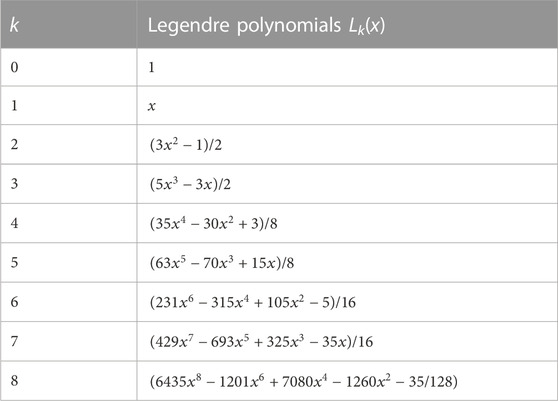
We should select a set of suitable orthogonal polynomials according to Section 4. Table 2 lists the first eight orders of Legendre polynomials of 1-D random variables for univariate analysis.
Figure 6 presents the comparison RCS results of analytical and MoM–PCE for an infinite cylinder with three random variables. We first compute the bistatic RCS for 0 ≤ θsca ≤ 2π and θinc = 0 at 10 MHz. The ɛ1 = ∞ denotes that the cylinder is a perfect conductor. It can be seen in Figure 6A that the RCS is symmetric with respect to θsca. The 2nd PCE performs badly, and the accuracy increases from the 4th order. The expression of the 4th PCE shown in Figure 6A is
where x denotes the bistastic angle θsca and
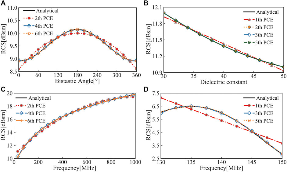
FIGURE 6. RCS value at the field point (1 × 10⁵, 0) in terms of four uniform random variables: (A) f =10MHz, ɛ1=∞; (B) f =10MHz, θsca =0; (C) θsca = π, ɛ1=∞; and (D) ɛ1=2.56, θsca =0.
It can be seen in Figure 6B that the back-scattering RCS value decreases as the dielectric constant increases. The 1st order of the PCE model shows some errors and the 2nd PCE performs fairly well, which can be expressed as Eq. 32.
Figure 6C shows the back-scattering RCS in terms of frequency. The 2nd PCE shows errors again, but they are not quite as apparent as they were in case (A). The 4th order model fits well, at least within the range of frequencies considered. The 6th PCE is free of errors as expected and expressed as Eq. 33. The higher frequencies correspond to higher results, which is approximately 19.8 dBsm at 1000 MHz.
Contrary to Figure 6C, the RCS does not follow a straight direction in terms of frequency, which is shown in Figure 6D. With the increase of frequency, the RCS value increases first and then decreases in the interval [130,150] MHz. The 1st PCE shows more errors with CV = 9.3% illustrated in Figure 7D. It can be seen that the 4th PCE performs fairly well, which can be expressed as Eq. 34.
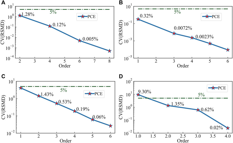
FIGURE 7. CV (RSMD) with respect to different variables. (A) PEC model, θsca ∈[0,2π], f =10MHz; (B) DIE model, ɛ1∈[30,50], f =10MHz, θsca =0; (C) PEC model, f ∈[1,1000] MHz, θsca = π; (D) DIE model, f ∈[130,150]MHz, ɛ1=2.56, θsca =0.
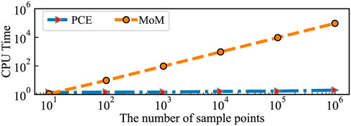
Figure 7 shows the CV values corresponding to Figure 6. The green line represents CV = 5%, which is much higher than most of the constructed models. Only one result in Figure 7D created by the 1st PCE introduced higher CV, but the accuracy improved rapidly with the increase in the order. While ensuring accuracy, the PCE combined with the MoM could also increase the speed, which can be seen in Figure 8.
The aforementioned comparison is between the analytical and the PCE method solution with 1-D independent variables. The PCE method can also fit well and even the independent variable is 2-D data.
5.2 Bivariate analysis
In this section, the MOM-PCE method is used to construct a surrogate model of the dielectric cylinder for electromagnetic scattering analysis. The frequency is 11 MHz, ɛ0 and μ0 values of the outer region are 1, and the radius of the cylinder model is 1. We assume the dielectric constant ɛ1 as x1 ∈ [30, 50] and bistatic angle θsca as x2 ∈ [0, 360]. The random sample points put into the PCE module are obtained from the MoM results. Table 3 lists the 2-D Legendre expressions.
The final expressions of the surrogate model with the 3rd and 4th order can be written as
The bivariate results with surrogate models of the 3rd and 4th order are shown in Figure 9A–C, which show the surface and contour solution with the same chromatic level of [10.5,12]. The red region represents a higher value of the corresponding model, and the blue region represents a lower value. It can be seen that the 4th PCE fits better as its trend and color distribution are more similar to those of the analytical solution. The relative errors are shown in Figures 9D, E using the same chromatic level of [0, 1%]. It can be clearly seen that the 4th PCE results have much higher accuracy. In addition, the CV (RMSD) of the 3rd PCE is 0.32%, and that of the 4th PCE is 0.12%, which are both much lower than 5%. In addition, it shows good agreement near the specular angles but fair to poor elsewhere, as shown in Figure 9E. It is also clear from the red region in Figure 9D that the margin of error in the interval is higher, which may be due to the Runge phenomenon.
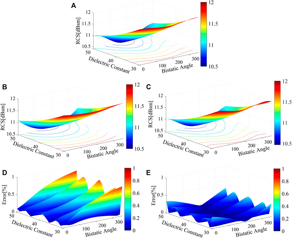
FIGURE 9. Surface results of the bivariate analysis with dielectric constant and bistatic angle: (A) analytical solution, (B) 3rd PCE result, (C) 4th PCE result, (D) relative error of the 3rd PCE model, and (E) relative error of the 4th PCE model.
6 Conclusion
In this paper, the method of moments is accelerated by polynomial chaos expansion to construct a surrogate model for electromagnetic scattering analysis. The triangle basic functions are used to discretize the surface integral equations (EFIE, MFIE, and CFIE) with MoM, and the input variables are sampled uniformly combined with Legendre orthogonal polynomials to construct the surrogate model of electromagnetic RCS. Bistatic angle, incident frequency, and dielectric constant are considered the source of systematic uncertainty. First, three different parameters are considered for univariate analysis to construct the corresponding surrogate model. The RCS and CV results of the MoM–PCE method are compared with the analytical solutions to verify the correctness of the algorithm proposed in this work, which performs fairly well. Then, the CPU time consumption of the MoM–PCE method is compared with that of MoM. It is found that the PCE method has a significant advantage in the calculation speed, especially when the number of sample points is huge. Finally, the bivariate analysis is carried out with the bistatic angle and dielectric constant with a dielectric conductor. The result shows that the PCE method is still efficient, and high order of PCE often leads to high accuracy. In general, it is verified that the MoM based on PCE presents great accuracy and efficiency.
Future work is required to extend the proposed algorithm into 3D electromagnetic sensitivity analysis and optimization analysis for practical engineering problems.
Data availability statement
The original contributions presented in the study are included in the article/Supplementary Material, further inquiries can be directed to the corresponding author.
Author contributions
Conceptualization, XY; data curation, YM; formal analysis, YH and RH; investigation, YH and ZW; methodology, XY and ZW; project administration, XY, software, YM and ZW; supervision, XY and YH; validation, YH and RH; visualization, YM and RH; writing—original draft, XY, YM, and ZW. All authors have read and agreed to the published version of the manuscript.
Conflict of interest
The authors declare that the research was conducted in the absence of any commercial or financial relationships that could be construed as a potential conflict of interest.
Publisher’s note
All claims expressed in this article are solely those of the authors and do not necessarily represent those of their affiliated organizations, or those of the publisher, the editors, and the reviewers. Any product that may be evaluated in this article, or claim that may be made by its manufacturer, is not guaranteed or endorsed by the publisher.
References
1. Chen H, Li G, Lu LJ, Liang DF, Weng X, Xie H, et al. Design of tapered periodic meta-surfaces for suppressing edge electromagnetic scattering. Mater Sci Forum (2020) 998:203–8. doi:10.4028/www.scientific.net/msf.998.203
2. Li M, Yue X, Ding F, Ning B, Wang J, Zhang N, et al. Focused lunar imaging experiment using the back projection algorithm based on sanya incoherent scatter radar. Remote Sensing (2022) 14:2048. doi:10.3390/rs14092048
3. He Y, Yang Q, Gao X. Comprehensive optimization design of aerodynamic and electromagnetic scattering characteristics of serpentine nozzle. Chin J Aeronautics (2021) 34:118–28. doi:10.1016/j.cja.2020.10.010
4. Bahret WF, Sletten CJ. A look into the future of radar scattering research and development. Proc IEEE (2005) 53:786–95. doi:10.1109/proc.1965.4056
5. Ma J, Jin K, Zheng X. Radar cross-section of a target and attenuation of electromagnetic waves in sandstorms. J Quantitative Spectrosc Radiative Transfer (2023) 294:108388. doi:10.1016/j.jqsrt.2022.108388
6. Wang X, Yang F, Liu C, Liu Y, Gong H, Zhang H. Fast wide-band rcs analysis of the coated target based on pbr using efie-pmchwt and the Chebyshev approximation technique. Electronics (2023) 12:923. doi:10.3390/electronics12040923
7. Gedney S. The finite element method in electromagnetics [book review]. Antennas Propagation Mag IEEE (1994) 36:75–6. doi:10.1109/MAP.1994.1068064
8. Hadi MF, Esmaeili SA. Cuda fortran acceleration for the finite-difference time-domain method. Comput Phys Commun (2013) 184:1395–400. doi:10.1016/j.cpc.2013.01.006
9. Rius JM, FerrandoGreco M, Jofre L. Greco: Graphical electromagnetic computing for RCS prediction in real time. IEEE Antennas Propagation Mag (1993) 35:7–17. doi:10.1109/74.207645
10. Andersh D, Moore J, Kosanovich S, Kapp D, Bhalla R, Kipp R, et al. Xpatch 4: The next generation in high frequency electromagnetic modeling and simulation software. In: Record of the IEEE 2000 International Radar Conference [Cat. No. 00CH37037]; 12-12 May 2000; Alexandria, VA, USA (2000). p. 844–9. doi:10.1109/RADAR.2000.851945
11. Tabakcioglu M. Extensive comparison results of coverage map of optimum base station location of digital terrain with utd based model. Prog Electromagnetics Res M (2020) 97:69–76. doi:10.2528/PIERM20080405
12. Ling H, Chou RC, Lee SW. Shooting and bouncing rays: Calculating the rcs of an arbitrarily shaped cavity. IEEE Trans Antennas Propagation (1989) 37:194–205. doi:10.1109/8.18706
13. Brem R, Eibert T. A magnetic field integral equation based iterative solver for scattered field prediction. Prog Electromagnetics Res M (2014) 40:27–35. doi:10.2528/pierm14072506
14. Chen L, Lian H, Xu Y, Li S, Liu Z, Atroshchenko E, et al. Generalized isogeometric boundary element method for uncertainty analysis of time-harmonic wave propagation in infinite domains. Appl Math Model (2023) 114:360–78. doi:10.1016/j.apm.2022.09.030
16. Chen L, Lian H, Natarajan S, Zhao W, Chen X, Bordas S. Multi-frequency acoustic topology optimization of sound-absorption materials with isogeometric boundary element methods accelerated by frequency-decoupling and model order reduction techniques. Comput Methods Appl Mech Eng (2022) 395:114997. doi:10.1016/j.cma.2022.114997
17. Chen L, Lian H, Liu Z, Gong Y, Zheng C, Bordas S. Bi-material topology optimization for fully coupled structural-acoustic systems with isogeometric FEM-BEM. Eng Anal Boundary Elem (2022) 135:182–95. doi:10.1016/j.enganabound.2021.11.005
18. Miller EK, Medgyesi-Mitschang LN, Newman EH. Computational electromagnetics: Frequency-domain method of moments. Piscataway: IEEE Press (1992).
19. Wang J. Generalised moment methods in electromagnetics. Microwaves Antennas Propagation Iee Proc H (1990) 137:127–32. doi:10.1049/ip-h-2.1990.0024
20. Chen L, Li H, Guo Y, Chen P, Atroshchenko E, Lian H. Uncertainty quantification of mechanical property of piezoelectric materials based on isogeometric stochastic FEM with generalized nth-order perturbation. Eng Comput (2023) 1–21. doi:10.1007/s00366-023-01788-w
21. Chen L, Wang Z, Peng X, Yang J, Wu P, Lian H. Modeling pressurized fracture propagation with the isogeometric BEM. Geomechanics Geophys Geo-Energy Geo-Resources (2021) 7:51. doi:10.1007/s40948-021-00248-3
22. Chen L, Zhang Y, Lian H, Atroshchenko E, Ding C, Bordas SP. Seamless integration of computer-aided geometric modeling and acoustic simulation: Isogeometric boundary element methods based on catmull-clark subdivision surfaces. Adv Eng Softw (2020) 149:102879. doi:10.1016/j.advengsoft.2020.102879
23. Chen L, Lu C, Lian H, Liu Z, Zhao W, Li S, et al. Acoustic topology optimization of sound absorbing materials directly from subdivision surfaces with isogeometric boundary element methods. Comput Methods Appl Mech Eng (2020) 362:112806. doi:10.1016/j.cma.2019.112806
24. Chen L, Lu C, Zhao W, Chen H, Zheng CJ. Subdivision surfaces—Boundary element accelerated by fast multipole for the structural acoustic problem. J Theor Comput Acoust (2020) 28:2050011–1. doi:10.1142/S2591728520500115
25. Xu Y, Li H, Chen L, Zhao J, Zhang X. Monte Carlo based isogeometric stochastic finite element method for uncertainty quantization in vibration analysis of piezoelectric materials. Mathematics (2022) 10:1840. doi:10.3390/math10111840
26. Chen L, Cheng R, Li S, Lian H, Zheng C, Bordas SP. A sample-efficient deep learning method for multivariate uncertainty qualification of acoustic–vibration interaction problems. Comput Methods Appl Mech Eng (2022) 393:114784. doi:10.1016/j.cma.2022.114784
27. Chen L, Liu C, Zhao W, Liu L. An isogeometric approach of two dimensional acoustic design sensitivity analysis and topology optimization analysis for absorbing material distribution. Comput Methods Appl Mech Eng (2018) 336:507–32. doi:10.1016/j.cma.2018.03.025
28. Chen L, Marburg S, Zhao W, Liu C, Chen H. Implementation of isogeometric fast multipole boundary element methods for 2d half-space acoustic scattering problems with absorbing boundary condition. J Theor Comput Acoust (2018) 27:1850024. doi:10.1142/S259172851850024X
29. Chen L, Lian H, Liu Z, Chen H, Atroshchenko E, Bordas S. Structural shape optimization of three dimensional acoustic problems with isogeometric boundary element methods. Comput Methods Appl Mech Eng (2019) 355:926–51. doi:10.1016/j.cma.2019.06.012
31. Kim T, Han WS, Piao J, Kang PK, Shin J. Predicting remediation efficiency of lnapls using surrogate polynomial chaos expansion model and global sensitivity analysis. Adv Water Resour (2022) 163:104179. doi:10.1016/j.advwatres.2022.104179
32. Xiu D, Karniadakis GE. A new stochastic approach to transient heat conduction modeling with uncertainty. Int J Heat Mass Transfer (2003) 46:4681–93. doi:10.1016/s0017-9310(03)00299-0
33. Nath K, Dutta A, Hazra B. Iterative polynomial dimensional decomposition approach towards solution of structural mechanics problems with material randomness. Probabilistic Eng Mech (2021) 66:103159. doi:10.1016/j.probengmech.2021.103159
34. Ghanem R. Ingredients for a general purpose stochastic finite elements implementation. Comput Methods Appl Mech Eng (1999) 168:19–34. doi:10.1016/s0045-7825(98)00106-6
35. Nabil EM, Seaid M. Data-driven polynomial chaos expansions for characterization of complex fluid rheology: Case study of phosphate slurry. Reliability Eng Syst Saf (2021) 216:107923. doi:10.1016/j.ress.2021.107923
36. Trinh VH, Li D, He M, Li X. Modeling sound absorption of graded foam absorbers via polynomial surrogate technique. J Theor Comput Acoust (2022) 30:2150027. doi:10.1142/S2591728521500274
37. Mocayd NE, Mohamed MS, Seaid M. Non-intrusive polynomial chaos methods for uncertainty quantification in wave problems at high frequencies. J Comput Sci (2021) 53:101344. doi:10.1016/j.jocs.2021.101344
38. Stievano IS, Manfredi P, Canavero FG. Carbon nanotube interconnects: Process variation via polynomial chaos. IEEE Trans Electromagn Compatibility (2012) 54:140–8. doi:10.1109/temc.2011.2171490
39. Li H, Zhao J, Guo X, Cheng Y, Xu Y, Yuan X. Sensitivity analysis of flexoelectric materials surrogate model based on the isogeometric finite element method. Front Phys (2022) 10. 1111159. doi:10.3389/fphy.2022.1111159
40. Xiu D, Karniadakis GE. The wiener–askey polynomial chaos for stochastic differential equations. SIAM J Scientific Comput (2002) 24:619–44. doi:10.1137/s1064827501387826
Appendix A. Analytical solution
In this section, we consider the PEC and DIE infinite cylinder impinged by electromagnetic plane waves with different polarization directions. The analytical solution of the scattering electric field is described in detail. The scattered electric field under TE-polarized incident waves can be expressed as
where
For a dielectric cylinder, the series coefficients
where r is the radius of the cylinder. The scattered far electric field is
The aforementioned expression is the analytical solution of the scattered electric field under TE polarization, and the expressions of the scattered magnetic field under TM polarization are as follows.
where
For the dielectric cylinder, the coefficients
The scattered far magnetic field is
Keywords: method of moments, polynomial chaos expansion, radar cross-section, surrogate model, electromagnetic scattering
Citation: Yuan X, Ma Y, Huang Y, Huo R and Wang Z (2023) The method of moments for electromagnetic scattering analysis accelerated by the polynomial chaos expansion in infinite domains. Front. Phys. 11:1178466. doi: 10.3389/fphy.2023.1178466
Received: 02 March 2023; Accepted: 31 March 2023;
Published: 18 April 2023.
Edited by:
Pei Li, Xi’an Jiaotong University, ChinaReviewed by:
Yunfei Gao, Hohai University, ChinaChuang Lu, University of Science and Technology of China, China
Copyright © 2023 Yuan, Ma, Huang, Huo and Wang. This is an open-access article distributed under the terms of the Creative Commons Attribution License (CC BY). The use, distribution or reproduction in other forums is permitted, provided the original author(s) and the copyright owner(s) are credited and that the original publication in this journal is cited, in accordance with accepted academic practice. No use, distribution or reproduction is permitted which does not comply with these terms.
*Correspondence: Yujing Ma, amluZ2xleWVhaDE5OEAxNjMuY29t
 Xiaohui Yuan
 Yujing Ma
 Yajun Huang2
 Zhongwang Wang
