- Deutsches Elektronen-Synchrotron DESY, Hamburg, Germany
The High Duty Cycle (HDC) upgrade is a proposed improvement to the existing European X-ray Free Electron Laser (EuXFEL) to extend the pulsed RF duty factor from the actual value of around 1% to more than 5% up to Continuous Wave (CW). To implement this upgrade, the loaded quality factor (QL) of the superconducting cavities will increase by more than one order of magnitude. This will result in shrinking the cavity bandwidth to values as low as a few Hertz. Since the Lorentz Force Detuning (LFD) experienced during the accelerating field buildup is of hundreds of Hertz, the Low-Level RF (LLRF) system has to accurately track and control the cavity resonance frequency to obtain the desired accelerating gradient. Moreover, ponderomotive instabilities have to be suppressed to achieve stability during beam acceleration. Since LFD is a repetitive disturbance in cavity frequency, the correction to its effects can be implemented as a feedforward compensation on the piezoelectric tuners of the cavity. Initial results on the simulation of feedforward resonance control in the HDC regime are discussed in this proceeding.
1 Introduction
The European X-ray Free Electron Laser (EuXFEL) is a hard X-ray FEL based on superconducting TESLA-type cavities operating in pulsed mode [1, 2]. The proposed High Duty Cycle (HDC) upgrade would make the operation of the machine in Continuous Wave (CW) mode possible, with a final beam energy of 8 GeV [3]. Due to the requirements of the experimental community, the EuXFEL HDC upgrade will also enable a Long Pulse (LP) mode of operation. In such a mode of operation, the experiments will benefit from beam energies higher than 10 GeV and, at the same time, produce a number of bunches per second comparable to machines operated in CW [4]. The LP mode is realized by extending the duty factor of the EuXFEL pulse flattop from 0.65% to 5–50%. For this mode of operation, it is planned to use the same RF amplifiers as for the CW mode and not increase the cryogenic heat load compared to the continuous case. The use of either a CW or LP mode on EuXFEL will be scheduled depending on the requirements of the experimental campaign. From the Low-Level RF (LLRF) perspective, the most significant change is the requirement to drive the RF superconducting accelerating cavities with a loaded quality factor (QL) of 6 ⋅ 107, one order of magnitude higher than the current value of 4.6 ⋅ 106. This change is required to lower the cavity RF power consumption to the kilowatt level [5, 6]. Such a change will result in an RF half bandwidth (f1/2) of 10.8 Hz. Due to this change, the superconducting cavities will be an order of magnitude more sensitive to mechanical disturbances. These disturbances originate from external (microphonics) and internal Lorentz Force Detuning (LFD) vibrations. A particular concern is the LFD-generated ponderomotive instabilities when driving the resonators at their maximum foreseen accelerating voltage (Vacc) of 20 MV. Considering a static LFD value klfd normalized to the active electrical length of the TESLA cavity (1.038 m) of up to 1.5HzMV−2, the ratio between the LFD and the cavity half bandwidth will be.
As explained in Schulze [8], such a value for
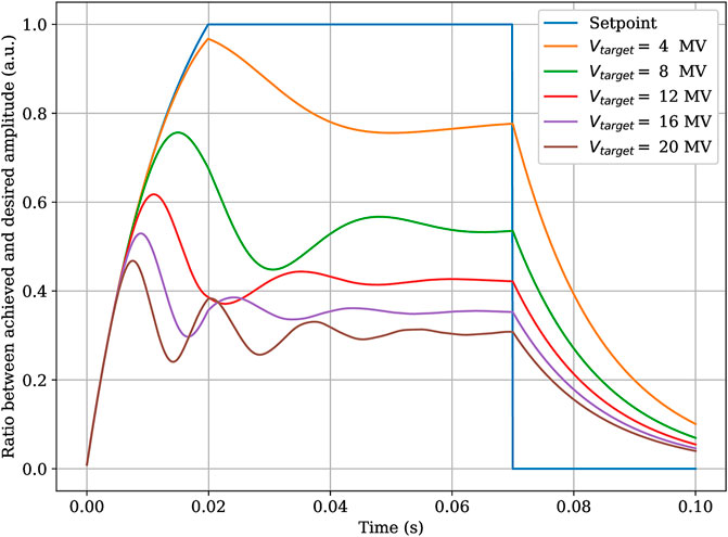
FIGURE 1. Simulation of the ratio between the target and achieved Vacc without any active detuning compensation. The effect of LFD-generated ponderomotive instabilities increases at higher gradients. The cavity parameters are taken from Czarski et al. [7].
Therefore it is of extreme importance to first develop a detuning-correcting method to drive the field of the cavities at a level where closed-loop operation is possible and, at the same time, not do not exceed the RF power budget of (6 kW) foreseen for the HDC upgrade. Once such a condition is realized, the residual field error will be then regulated by the RF feedback controller which operates at faster timescales compared to typical mechanical disturbances. Such scheme is necessary to realize a field regulation of 0.01% on amplitude and 0.01 deg on phase required by the EuXFEL experiments [10]. The detuning control method has to be implemented in a reliable and automated way due to its criticality in the correct operation of the accelerator. For this, the LLRF system must control the piezoelectric cavity tuners to compensate for LFD-generated effects [10, 11]. To simulate the control algorithms, an accurate mechanical model of the accelerating cavity is needed. Previous work already proved the feasibility of implementing an LFD-compensating scheme for gradients up to 14MVm−1 [12].
In this paper, the mechanical system model used in the simulations is given in Section 2. A feedforward control approach is presented in Section 3. Additionally, simulations using the Iterative Learning Control (ILC) algorithm are presented in Section 4 [13]. Such an algorithm is already in use in particle accelerators for RF and beam trasient compensation [14–17]. The advantage of using ILC is that repetitive un-modeled detuning disturbances can be rejected in an adaptive way. A challenge of using ILC for detuning compensation in high QL cavities is the presence of strong nonlinearities and hysteretic behaviour that might worsen the convergence properties of the algorithm. Therefore, in this paper, some simple modifications on the ILC algorithm were studied to limit the effect of ponderomotive instabilities. The final considerations are given in Section 5.
2 System model
The dynamics of the detuning in superconducting cavities can be described as the result of the excitation of a series of second-order mechanical resonances. These mechanical resonances can be either excited by the radiation pressure by the accelerating field or by external microphonics disturbances
Where μ is the mechanical mode index, Δf(μ) is the detuning contribution of the mode, ω(μ), Q(μ) and δ(μ) are the angular resonance frequency, quality factor and coupling with the piezoelectric actuator. u(t) is the piezoelectric input variable, controllable by the LLRF system, while ν(μ)(t) is the microphonic noise. ν(μ)(t) might be not synchronized with the accelerator timing. In general, an effective resonance control system requires driving u(t) so the detuning Root Mean Square (RMS) is smaller than the half bandwidth
To minimize the RF power required to drive the cavity at a certain accelerator voltage [5].
In this work, we ignore the problem of rejecting unsynchronous detuning originating from ν(μ)(t) since the repetitive LFD-generated disturbance is around two orders of magnitude higher [18]. The compensation of the unsynchronized part of ν(μ)(t) will be addressed in future studies.
3 Feedforward control
During the nominal operation of EuXFEL HDC, the accelerating field Vacc(t) will be required to have a well-defined periodic structure repeated in time with a repetition rate of 1 Hz. Such a pulse will have three distinct regions. These are the filling, flattop, and decay regions [19]. In the HDC upgrade, the filling region will last 20 ms. The flattop region length will be between 50 ms and 500 ms depending on the resulting dynamic heat load and cryogenic capacity [20]. The reference trajectory Vref(t) is then defined
Where tfill, tflat, tdecay are the starting times for the filling, flattop, and decay regions, Vflat is the desired accelerating voltage at flattop. Since Eq. 4 describes the desired field, it can be inserted in Eq. 2 to find the radiation pressure-induced detuning excitation and, consequently, the function for u(t) that achieves a perfect disturbance compensation. To do this ω(μ), Q(μ) and δ(μ) have to be determined. Alternatively, a transfer function approach can be used by measuring the step response to
Eq. 5 can be used in the simulations to see if it is sufficient to prevent the occurrence of ponderomotive instabilities.
Figure 2 shows the shape of the feedforward piezoelectric tuner drive of Eq. 5.
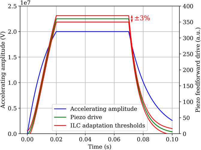
FIGURE 2. Accelerating voltage pulse structure at 20 MV and piezo feedforward drive generated using Eq. 5. Additionally, the learning thresholds for the clipped ILC algorithm are shown. The ILC correction magnitude is constrained to be within ± 3% the feedforward value at flattop.
Figure 3 shows a simulation of an accelerating cavity when the zero-order feedforward correction is used. The LFD effects are significantly reduced compared to Figure 1 even though the dynamics of the cavity is not taken into account in the feedforward signal compitation. The sharp transition between the different pulse regions produces the residual excitation of the mechanical resonances.
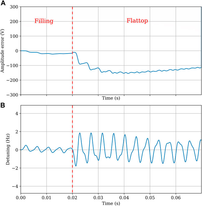
FIGURE 3. Simulation of the accelerating voltage error (A) and detuning (B) when the zero-order piezo feedforward is applied. The cavity system is simulated with an open RF loop. The simulation shows that in the flattop, an amplitude error of 200 V over an accelerating field of 20 MV. δ(μ) = 0.33 Hz. The residual detuning oscillation is ±2 Hz.
4 Iterative learning control
The correction of the residual mechanical oscillations resulting from the use of Eq. 5 and unmodeled detuning disturbances in TESLA-like cavities is challenging using white-box approaches [21]. Therefore, an adaptive gray-box ILC method is used. The idea is that future RF pulses can be corrected adaptively using the detuning information acquired in past pulses. An ILC-like method is already implemented at EuXFEL [22]. However, the difference in pulse length and QL with respect to the HDC upgrade makes it unsuitable in LP mode due to the absence of strong nonlinear ponderomotive effects. For the simulation tests in LP mode, a modified discrete Arimoto-like update law
Is chosen. In the above formulation, the classical Arimoto algorithm was changed to take into account the time-delay in the step response that originate from the high quality factor mechanical resonances. The adaptive correction component Δuk(n) is summed with Eq. 5 to give the piezo driving signal for a pulse identified with k. n is the sample within the pulse. The simulations use a sample rate of 5 kHz. Such a sample rate is roughly ten times the highest resonance frequency of the set of parameters used in the simulations [7]. d is the sample delay and is chosen by
with h(n) the impulse response of Eq. 2. For the set of parameters used in the simulations d = 3. The controller gain γ is empirically found to be ≃ − 0.15 by looking at the value that gives the fastest algorithm convergence. Q(q) is a second order lowpass filter with a bandwidth of 1 kHz synthetized and applied using the routines butter and sosfiltfilt of the package SciPy [23]. Q(q) prevents the growth of high-frequency noise at increasing k. A benefit of the method of Eq. 6 is the low computational complexity. A mechanical model-aware ILC might give better results in terms of disturbance rejection. However it would require further theoretical study. The reduction in detuning resulting from the application of Eq. 6 is simulated for a cavity driven at 20 MV for the following cases.
• Static detuning of 0 Hz (tuned)
• Static detuning of −5.4 Hz (−f1/2/2) (under-tuned)
• Static detuning of 5.4 Hz (f1/2/2) (over-tuned)
• Gaussian microphonics with a standard deviation of 0.5 Hz
• Gaussian microphonics with a standard deviation of 0.5 Hz plus a sinuisoidal component with a frequency of 50 Hz and an amplitude 5 Hz
The detuning disturbances of the above list are chosen to be similar to the ones observed in working particle accelerators and test facilities [18].
Figure 4 shows the convergence of the modified Arimoto ILC. For the tuned and under-tuned case, the detuning converges monotonically to values of 0.02 − 0.03 Hz RMS. The uncorrelated microphonics contributions dominate the detuning RMS for the trace affected by gaussian noise. Therefore, in this case, the ILC cannot decrease the pulse detuning noticeably. Still, the detuning remains in the order of 1 Hz RMS, fulfilling the requirement of Eq. 3. The most interesting cases are the over-tuned simulation and the one affected by sinusoidal microphonics. The initial detuning RMS is over 300 Hz and stays constant at a level of 40 Hz for both cases between k = 25 and k = 100. Then the detuning RMS starts decreasing and reaches a value of 1 Hz at k = 120. The explanation for this behaviour is that the simulated cavity, when over-tuned due to static detuning or microphonics, experiences a static drop [8] that detunes positively the cavity by several hundred Hertz. Therefore the ILC learns an invalid correction for the trace points affected by the static drop.
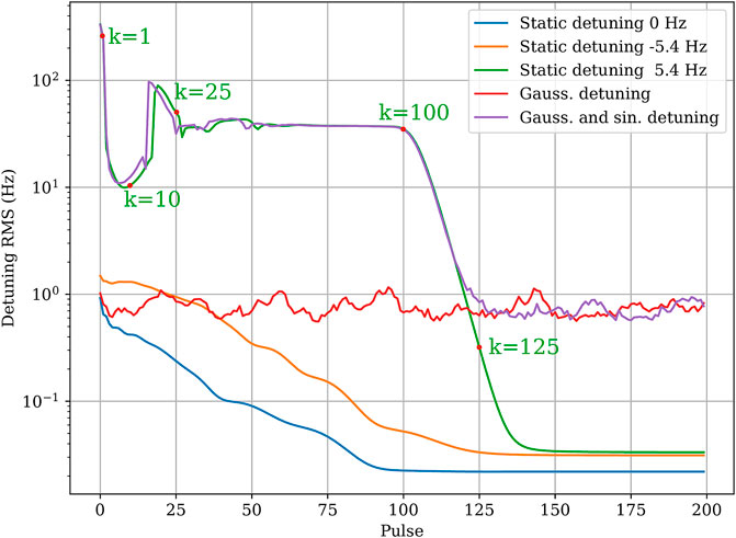
FIGURE 4. Detuning RMS in the filling and flattop region as a function of the pulse number for different types of detuning disturbances. The system is adapted using the ILC algorithm of Eq. 6.
After the ILC under-tunes the cavity enough to prevent the static drop from happening, it has to ’unlearn’ the invalid part of the correction for the RMS detuning value to decrease again (Figure 5). At a repetition rate of 1 Hz, the tuning might reach acceptable RMS levels only after 2 min. This delay would complicate the machine setup operations because the operators would need to wait until the algorithm converges to continue the accelerator commissioning. A possible improvement is to modify Eq. 6 to constrain the values in the ILC correction table within a pre-determined range
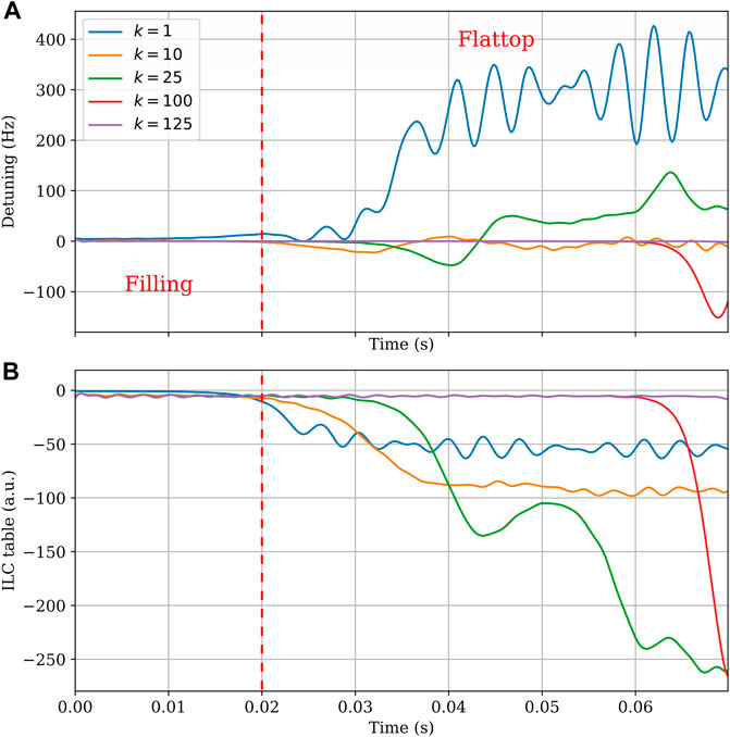
FIGURE 5. Detuning (A) and ILC table (B) at different values of k for the first version of the ILC algorithm. The simulation is performed with a static predetuning of 5.4 Hz. The evaluated k corresponds to the ones highlighted in Figure 4. As can be seen in plot (B), due to the presence of the monotonic instability, the ILC algorithm learns initially an incorrect state. Such an incorrect state requires around 125 ILC iteration to be cleared.
Where
Δulearn determines the maximum learning range for the ILC algorithm. Therefore, even in the case of a static drop, the controller does not learn an excessive tuning correction. From the simulations, Δulearn = 10 is enough for the final correction to be represented in the tables. Using Eq. 8, a much faster convergence is achieved for the over-tuned case and the one affected by sinusoidal microphonics. For pulses with k > 3, a detuning
5 Final remarks
This article presented a study of a possible feedforward detuning compensation scheme for superconducting cavities. The simulation of the compensation of the ponderomotive instabilities in TESLA cavities driven at Vacc = 20 MV and QL = 6 ⋅ 107 was possible by using a simple zero-order approximation. Additionally, the use of an Arimoto-like ILC algorithm allowed the compensation of the disturbances generated by the residual un-modeled mechanical dynamics in the presence of microphonics and ponderomotive instabilities. Clipping the values of the ILC controller not only allowed reaching an acceptable detuning root mean square values after just 3 s of operation but limited the amplitude of the piezo driving signal within ± 3% the value already provided by the static feedforward correction of Eq. 5. Since real piezoelectric tuners can be damaged when driven at high voltage values, such a technique could help increase the lifespan of these actuators. The approach of limiting or stopping the correction learning of adaptive controller when an anomalous condition is met is already in used at European XFEL for RF. These results show for the first time the feasibility of performing resonance control in high-duty cycle pulsed mode superconducting accelerators even when the cavity bandwidth is of few Hertz. Further research will concentrate on using a more accurate model-aware feedforward compensation scheme to minimize the mechanical excitation between pulse region transitions. Also, the ILC will need a more sophisticate exception handling mechanism to avoid learning invalid corrections during other anomalous conditions, like cavity quenches or amplifier trips, that might happen during operations. The presented compensation methods will be experimentally tested in the forthcoming year at DESY module superconducting test facilities.
Data availability statement
The raw data supporting the conclusion of this article will be made available by the authors, without undue reservation.
Author contributions
AB contributed to the idea, design, and simulation of the feedforward and ILC control scheme for resonance control in long pulse mode of operation. JB and HS contributed to the requirements of the resonance controller for the European XFEL HDC upgrade. CS contributed with consulting on the use of the ILC technique. All authors contributed to the article and approved the submitted version.
Funding
This work is supported by the Helmholtz institute and by European XFEL GmbH.
Conflict of interest
The authors declare that the research was conducted in the absence of any commercial or financial relationships that could be construed as a potential conflict of interest.
Publisher’s note
All claims expressed in this article are solely those of the authors and do not necessarily represent those of their affiliated organizations, or those of the publisher, the editors and the reviewers. Any product that may be evaluated in this article, or claim that may be made by its manufacturer, is not guaranteed or endorsed by the publisher.
References
1. Aune B, Bandelmann R, Bloess D, Bonin B, Bosotti A, Champion M, et al. Superconducting TESLA cavities. Phys Rev Spec Topics-Accel Beams (2000) 3:092001. doi:10.1103/physrevstab.3.092001
3. Sekutowicz J, Ayvazyan V, Barlak M, Branlard J, Cichalewski W, Grabowski W, et al. Research and development towards duty factor upgrade of the European X-Ray Free Electron Laser linac. Phys Rev Spec Topics-Accel Beams (2015) 18:050701. doi:10.1103/physrevstab.18.050701
4. Brinkmann R, Schneidmiller E, Sekutowicz J, Yurkov M Prospects for CW and LP operation of the European XFEL in hard X-ray regime. Nucl Instr Methods Phys Res Section A: Acc Spectrometers, Detectors Assoc Equip (2014) 768:20–5. doi:10.1016/j.nima.2014.09.039
5. Padamsee H RF superconductivity: Science, technology, and applications. John Wiley & Sons (2009).
6. Neumann A, Anders W, Kugeler O, Knobloch J Analysis and active compensation of microphonics in continuous wave narrow-bandwidth superconducting cavities. Phys Rev Spec Topics-Accel Beams (2010) 13:082001. doi:10.1103/physrevstab.13.082001
7. Czarski T, Pozniak KT, Romaniuk RS, Simrock S Tesla cavity modeling and digital implementation with fpga technology solution for control system development. In: Photonics Applications in Astronomy, Communications, Industry, and High-Energy Physics Experiments II, 5484. SPIE (2004). p. 111–29.
8. Schulze D (1972). Ponderomotive stability of RF resonators and resonator control systems. Tech. rep.,. FR Germany: Kernforschungszentrum Karlsruhe, Inst. fuer Experimentelle Kernphysik.
9. Bellandi A, Branlard J, Eichler A, Pfeiffer S Integral resonance control in continuous wave superconducting particle accelerators. IFAC-PapersOnLine (2020) 53:361–7. doi:10.1016/j.ifacol.2020.12.186
10. Branlard J, Ayvazyan G, Ayvazyan V, Grecki M, Hoffmann M, Jezynski T, et al. The European XFEL LLRF system. IPAC (2012) 12:55–7.
11. Bosotti A, Paparella R, Albrecht C Development of an acceptance test procedure for the xfel sc cavity tuners. In: Proceedings, 23rd Conference, PAC'09 (2009).
12. Cichalewski W, Sekutowicz J Long pulse operation of the E-XFEL cryomodule (2022). JACoW IPAC2022, TUPOST018. doi:10.18429/JACoW-IPAC2022-TUPOST018
14. Kichhoff S, Schmidt C, Lichtenberg G, Werner H An iterative learning algorithm for control of an accelerator based free electron laser. In: 2008 47th IEEE Conference on Decision and Control (2008). p. 3032–7. doi:10.1109/CDC.2008.4739064
15. Pfeiffer S, Lichtenberg G, Schmidt C, Schlarb H Tensor techniques for iterative learning control of a free-electron laser. In: 2012 IEEE International Conference on Control Applications (2012). p. 160–5. doi:10.1109/CCA.2012.6402643
16. Qiu F, Michizono S, Matsumoto T, Miura T, Wibowo SB, Liu N Development of iterative learning and disturbance observer-based llrf control system for international linear collider. In: Proceedings of the 14th Annual Meeting of Particle Accelerator Society of Japan (2017). p. 490–2.
17. Shahriari Z, Dumont GA, Fong K Current-iteration non-causal iterative learning control for beam loading cancellation in particle accelerators. In: 2019 8th International Conference on Systems and Control (ICSC) (2019). p. 170–5. doi:10.1109/ICSC47195.2019.8950532
18. Bellandi A, Branlard J, Cruz JD, Aderhold S, Benwell A, Brachmann A, et al. Narrow bandwidth active noise control for microphonics rejection in superconducting cavities at LCLS-II (2022). arXiv preprint arXiv:2209.13896.
20. Walker N, Decking W, Branlard J, Sekutowicz J High-duty-cycle operations scenarios at the European XFEL accelerator Frontiers in Physics. In: Global developments towards continuous-wave free-electron lasers (2023).
21. Scheinker A Application of extremum seeking for time-varying systems to resonance control of rf cavities. IEEE Trans Control Syst Technol (2017) 25:1521–8. doi:10.1109/TCST.2016.2604742
22. Przygoda K, Butkowski L, Omet M, Hierholzer M, Grecki M, Branlard J, et al. Piezo controls for the European XFEL. In: 10th Int. Particle Accelerator Conf.(IPAC’19); 19-24 May 2019; Melbourne, Australia. Geneva, Switzerland: JACOW Publishing (2019). p. 3856–9.
Keywords: particle accelerators, LLRF, superconducting RF, free electron laser, control systems
Citation: Bellandi A, Branlard J, Schlarb H and Schmidt C (2023) Feedforward resonance control for the European X-ray free electron laser high duty cycle upgrade. Front. Phys. 11:1170175. doi: 10.3389/fphy.2023.1170175
Received: 20 February 2023; Accepted: 30 May 2023;
Published: 21 June 2023.
Edited by:
Subrata Das, National Institute for Interdisciplinary Science and Technology (CSIR), IndiaReviewed by:
Alexander Scheinker, Los Alamos National Laboratory (DOE), United StatesIgor Pogorelsky, Brookhaven National Laboratory (DOE), United States
Copyright © 2023 Bellandi, Branlard, Schlarb and Schmidt. This is an open-access article distributed under the terms of the Creative Commons Attribution License (CC BY). The use, distribution or reproduction in other forums is permitted, provided the original author(s) and the copyright owner(s) are credited and that the original publication in this journal is cited, in accordance with accepted academic practice. No use, distribution or reproduction is permitted which does not comply with these terms.
*Correspondence: Andrea Bellandi, YW5kcmVhLmJlbGxhbmRpQGRlc3kuZGU=
 Andrea Bellandi
 Julien Branlard
 Holger Schlarb