 Zhengrong Chen1
 Guangai Wu1Jun Zhou1*Chuanzhi Ai1Anshun Zhang1Xin Xie1
 Jianshu Wu1Xiangwei Kong2,3*
 Song Li2
- 1CNOOC Research Institute Co., Ltd., Beijing, China
- 2School of Petroleum Engineering, Yangtze University, Wuhan, China
- 3Hubei Key Laboratory of Oil and Gas Drilling and Production Engineering, Yangtze University, Wuhan, China
Temporary plugging technology is an important drilling technique for maintaining wellbore stability and resolving lost circulation problems. The key to its success lies in the use of materials that can form a tight and stable “temporary plugging layer” with certain pressure bearing capacity and a permeability close to zero in the loss channel near the wellbore. Experimental studies have been conducted to develop adhesion formulations for optimal temporary plugging materials, as the matching relationship between particle size and fracture width is critical [(0.5−1)/1]. By measuring the permeability of the temporary plugging layer under varying confining pressure with a soap foam flowmeter, researchers have been able to evaluate the effectiveness, degradation, and dosages of temporary plugging agents. It has been shown that a single-particle material, such as a walnut shell, has a smaller permeability than a hyperfine CaCO3 coated temporary plug layer. The latter, however, is less capable of bearing pressure. By combining different materials, such as walnut shells and hyperfine CaCO3 particles, the researchers were able to create a temporary plug layer that had the lowest permeability and did not change much at variable confining pressures. Its pressure-bearing capacity is strong and the temporary plug works well. Experiments have shown that a ratio of 2:1–3:1 of hyperfine CaCO3 and walnut shell particles work well for plugging a fracture system with particles of size 2–3 times the fracture width. It developed an evaluation method for temporary plugging agents, studied their plugging capability and degradation performance for reservoir conversion, and evaluated degradation performance after successful temporary plugging. The temporary plugging rate of the temporary plugging agent increased from 98.10% to 99.81%, and the maximum temporary plugging pressure is 50.39 MPa, which can be completely reduced at 150°C for 4 h, meeting the technical requirements of “dense temporary plugging, two-way pressure bearing” to some extent.
1 Introduction
The problem of lost circulation, the most serious form of reservoir damage, is common during deep and ultra-deep drilling. However, leakage from karst caves and large fracture vent types with large production intervals is rare and leakage control techniques are difficult to implement. Leakage control techniques should temporarily plug the fracture as a leaky channel. Studies of reservoir fracture stress sensitivity, multiple fracture dynamic widths, and ideal matching models for temporary plug materials with special properties such as high strength, high permeability, and high recovery rate are fundamental to the successful application of shielded temporary plug technology in fractured reservoirs [1–8].
As one of the core technologies for protecting oil and gas reservoirs, temporary plugging technology has been deeply studied by researchers [9–16]. The temporary plugging technology is mainly aimed at porous reservoirs with high permeability. Abrams first proposed the famous “one-third bridging rule” for the drilling fluid used to protect oil and gas reservoirs [17]. Luo et al. put forward the “two-thirds bridge building criterion” that can improve the stability of bridge building on the basis of the “one-third bridge building rule”. They believed that the average particle size of bridge blocking particles should be 1/2–2/3 of the average pore throat size of the formation. On this basis, they put forward the temporary shielding plugging technology [18]. Zhang et al. began to use the ideal temporary plugging theory and D90 temporary plugging new method (on the cumulative distribution curve of particle size composition, when the cumulative volume fraction of 90% of the particle diameter (D90) is equal to the maximum diameter of the formation pore throat, the temporary plugging effect is the best) to temporarily plug medium and high permeability reservoirs [19]. Liu Jing et al. considered the shielding temporary plugging of fracture pore type reservoirs with different fracture widths and pressure differences, studied the reasonable positive pressure difference of drilling fluid shielding temporary plugging and the temporary plugging effect under different fracture widths, and provided a reasonable basis for the effective application of shielding temporary plugging protection technology [20]. Yang et al. added appropriate bridging particles, filling particles, and deformation particles into the original working fluid according to the 2/3 bridging theory, pore throat size distribution, fracture characteristics, and particle size and distribution of various particles in the working fluid, and achieved good reservoir protection effect [21]. Based on the concept of temporary plugging, a technology called “temporary plugging” is proposed for fractured porous reservoirs with a crack width of 150 μm. According to the “1/3 bridging theory,” the particle size and crack width of the bridging temporary blockage should meet certain requirements. The best combination of temporary plugging materials is 2.0% bridging particles + 1.5% deformed particles, and the recovery rate of the natural flowback permeability is greater than 65.0% [22]. Bao et al. discussed the instability failure mechanism of a high-temperature temporary plugging layer by using a self-made high-temperature high-pressure fracture temporary plugging simulation experimental device. Three kinds of plugging materials, including micro filling particles, elastic deformation particles, and sheet filling particles, which are resistant to temperatures up to 220°C, were selected from the experiment. Two new plugging materials were made, namely, rigid bridging particles with high temperature resistance, high strength, and low density, and high temperature resistance and high strength fibers [23]. In view of the characteristics of high temperature, high pressure, and natural fracture development in ultra-deep fractured carbonate reservoir, based on the study of rock mineral composition, microstructure characteristics, and damage factors, a reservoir protection strategy of “drilling fluid performance control acid soluble temporary plugging system” is proposed, and a high-temperature acid soluble temporary plugging system consisting mainly of acid soluble fibers, acid soluble filler materials and elastic graphite is developed, The reservoir protection goal of “plugging and unlocking” has been realized [24]. Addagalla et al. designed the new phase-transforming loss circulation material (PTLCM) to pump easily and achieve thixotropic behavior under downhole conditions, resisting losses in the thief zone before setting it as a rigid plug with high compressive strength [25]. Vickers et al. investigated the effects of additive particle size and pore size dispersion on the performance of LCMs, ultimately reducing reservoir damage. It is shown that if the particle size and pore dispersion parameters of LCMs D10, D50, and D90 are the same, the reduction of drilling fluid leakage will be minimized [26]. All these studies indicate that the reduction of drilling fluid leakage must take into account the grain size distribution of LCMs. Alsaba et al. introduced the fibrous and flaky type LCMs, which can be capable of creating a tight defensive plugged zone against fractures and big, porous, and permeable voids in the reservoir formation. These LCMs can be effective to prevent heavy mud losses in drilling engineering [27]. Alireza et al., experimentally studied the productivity of various loss control materials (LCMs) in bentonite mud, evaluated the particle size distribution of LCMs based on API standards, investigated the loss of bentonite mud in various fractures via Bridging Testing Materials (BMT) apparatus [28]. Bao et al. experimentally studied the effect of LCM type, concentration, and particle size distribution on seal integrity through an LCM apparatus with a long fracture slot. The breaking pressure, fluid loss values, position, and thickness of plugging zone are the parameters for evaluating LCM performance [29]. Souza et al. experimentally studied the water-based fluid containing polymers as viscosifiers and lost-circulation materials (LCM), which evaluated the behavior of granular and fibrous materials and mixtures of them and their behavior and mechanisms of action in different sealing processes [30]. Temporary plugs are a proposed method for controlling leaks in channels ranging from tens of microns to millimeters. This is an important direction for potential lost circulation reservoir protection technology. By studying the change in the stability of the temporary plugging layer of plugging materials in fractures, we can extend the coverage of shielding temporary plugging technology to protect the width of fractures, quickly and efficiently achieving the goal of temporary plugging integration, and thus eliminating most induced losses in the “embryonic state.” The proposed technology has both advantages and limitations, and examples can help to better illustrate these aspects. By providing a more specific analysis, we can evaluate the effectiveness and potential of this technology in various scenarios.
The technical idea of temporary plugging and unplugging is also widely applied in the field of simulation and reconstruction of oil and gas reservoirs. In the aspect of temporary plugging and fracturing and acidizing for stimulation and reconstruction, degradable materials are mainly used as temporary plugging and diverting agents, which rely on the acid liquid to carry into the layer with good permeability and large flow coefficient, so as to achieve temporary plugging and diverting, thus achieving the purpose of reasonable placement of acid liquid in strongly heterogeneous reservoirs [31–34]. Multiple types of temporary plugging agents are selected according to the formation conditions to implement composite temporary plugging [35], which is conducive to improving the temporary plugging effect. Li et al. simulated and studied the non-mechanical temporary plugging steering process under different completion methods based on the 3D printing fracture rock plate simulation technology, selected the temporary plugging steering material with temperature resistance and pressure capacity, and evaluated the design parameters such as the content of temporary plugging steering material and the combination of particle size under different fractures and their temporary plugging capacity [36]. Wu et al. proposed a novel water-soluble polymer plug for fracturing, which was completely degraded at 70°C for 5–8 h by carrying out experimental evaluation tests, such as water absorption expansion rate [37].
Temporary plugging materials play a vital role in drilling engineering and in the development and stimulation of oil and gas fields. In this study, different temporary plugging materials were evaluated for their permeability and temporary plugging effect, and the temporary plugging layer formed by different compositions of temporary plugging materials was tested under varying confining pressure conditions. Moreover, the bridge temporary plugging formula of “tight temporary plugging and bidirectional pressure” was optimized, and the pressure stability and degradation performance of the plugging layer were experimentally evaluated. These results provide a useful reference for the use of temporarily effective blocking and bearing fracture systems in drilling and oil extraction. This paper describes an experimental design for various temporary plugging materials, evaluates the permeability and temporary plugging effect of different temporary plugging material compositions under varying confining pressure conditions, optimizes the bridge temporary plugging formula of “tight temporary plugging and bidirectional pressure,” and evaluates the pressure stability and degradation performance of the plugging layer experimentally. The experiments provide valuable reference information for temporary plugging techniques. In addition, we investigate the capability and degradation performance of temporary plugging, develop an evaluation method for temporary plugging for reservoir conversion, and evaluate the degradation performance after successful temporary plugging. Our findings can contribute to the improvement of temporary plug technology and the efficient development of oil and gas fields technology. In addition, the authors investigated the capability and degradation performance of temporary plugging, developed an evaluation method for reservoir conversion, and evaluated the degradation performance after successful temporary plugging.
2 Formulation optimization of temporary plugging agent
2.1 Experimental materials and instruments
Dense carbonate outcrops were selected and treated with Brazil splitting. The fractures in the walls were then filled with experimental material. To prepare the fracture for the experiment, a pretreatment of 20 MPa confining pressure was applied. This resulted in a fracture width of approximately 100 mesh (as shown in Figure 1). We selected walnut shell and coated ultra-fine CaCO3 as the indoor plugging materials to be tested, as shown in Figure 2 and Figure 3.
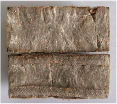
FIGURE 1. Fractured rock sample for experiment.
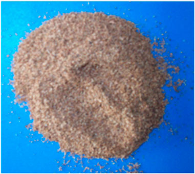
FIGURE 2. Walnut shell granule.

FIGURE 3. Superfine CaCO3.
A gas flow meter was used in the experiment to measure the gas permeability of the fractured rock sample. This equipment, independently developed, is composed of a nitrogen cylinder, core gripper, and special measuring cylinder (Figure 4), which is mainly based on the Darcy formula and is suitable for on-site measurement of the permeability of low porosity and low permeability rock samples. Measurements were performed by using nitrogen gas to penetrate the sample in a core holder, connecting a flow meter containing bubble water and creating bubbles to drive the gas upward through the holder. Due to the small bubble mass, the effect of gravity can be neglected and the rise velocity can be measured. By using Darcy’s formula, the permeability of the sample can be calculated.
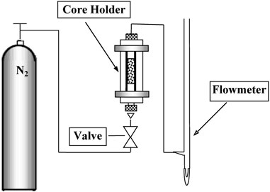
FIGURE 4. Soap foam flowmeter instrument.
2.2 Experimental scheme
(1) The design involves uniformly placing equal amounts of the plug material formula on the fracture surface as a temporary plug layer, and then tightly wrapping the fractured rock sample in the core holder.
(2) The oil pressure pump provides and controls the confinement pressure of the core gripper, while the nitrogen cylinder provides the gas and flow pressure.
(3) The pipes are connected according to the drawing procedure. The soapy water is placed in a rubber tube at the bottom of a special measuring cylinder and the tube is squeezed to create soap bubbles. These bubbles are driven upwards by the passage of N2 gas through the fractured rock sample, creating a driving force. The permeability of the fractured rock sample at varying confining pressures was then calculated by recording the rate of rise of a single soap bubble in the measuring cylinder to obtain the flow rate of gas at the exit.
(4) Five confining pressures were chosen for the gripper: 5, 10, 15, 20, and 30 MPa. At least five different flow pressure points are reasonably chosen to provide the confining pressure sequentially. After each pressure change, it is necessary to stabilize the system for 30 min. The rise rate of the foam was recorded at each flow pressure and the steady-state time was varied by 1–2 min. The error rate is ensured to be as small as possible.
(5) The gas flow rates for the different plug formulations were obtained by successively using the temporary plug formation in Table 1 as the temporary plug layer for the fractured rock samples.
(6) According to Eq. 1, the gas flow measured at the outlet is converted into the permeability of the fractured rock sample to obtain the permeability change rule of the temporary plugging layer with different plugging materials under the action of varying confining pressure.
Where, K is the permeability, 10−3 μm2.
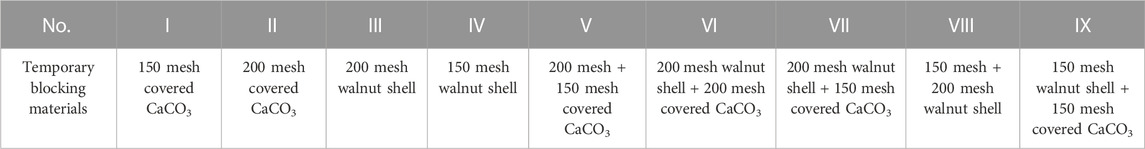
TABLE 1. Plugging layers with different materials.
2.3 Experimental results and discussion
2.3.1 Experimental results
Soap-foam flow meters were used to obtain permeability variations for nine species of plug material in fractured rock samples. The goal of the present study is to investigate the permeability of different temporary plug layers formed in fractured rocks under various confining pressures. As shown in Figure 6, the permeability is highest for the temporary plug layer formed by 200 meshes coated with ultra-fine CaCO3, indicating that the mismatch between particle size and fracture width makes the bridge unstable and vulnerable to destruction, resulting in a large permeability for the temporary plug layer. On the other hand, the permeability of the temporary plug layer formed by 150 mesh walnut shell particles is minimal and decreases with increasing confining pressure. This suggests that the temporary plug layer formed by walnut shell particles is the densest compared to other plug materials.
Comparing the permeability of the individual plug materials, Figure 7 shows that the permeability of the temporary plug layer formed by the walnut shell particles is smaller than that of the ultrathin CaCO3-coated film. Figure 7 shows that the permeability of the temporary plug layer formed by walnut shell particles is smaller than that of the ultrathin CaCO3-coated film, suggesting that the temporary plug layers formed by walnut shell particles in fractures tend to be denser due to their higher persistence at confining pressures compared to coated hyperfine CaCO3. Moreover, although walnut shells cannot form temporary plugs on their own due to their weak solubility, they can be an effective component in the production process of oil and gas development as temporary plugs.
An ideal temporary plug layer requires a mixture of different plug materials as shown in Figure 8. To compare and analyze the permeability of the temporary plug layer formed by 150 mesh-coated hyperfine CaCO3 and 200 mesh-coated hyperfine CaCO3, a temporary plug layer is formed by stabilizing bridges constructed by coating the fracture with ultrathin CaCO3, using the assistance of walnut-shell particles of small grain size and weak stiffness. As the confining pressure is increased, the coated hyperfine CaCO3 and walnut-shell particles become more compacted, thereby decreasing the permeability of the temporary plug layer. Although coated hyperfine CaCO3 can act as a bridge, it cannot effectively act as a compact temporary plug by deformation, as coated hyperfine CaCO3 films are brittle and nearly incompressible. However, the small deformation of the walnut-shell particles at confining pressure makes the temporary plug more compact, indicating that the gas permeability of the fractured rock sample is minimal at the macroscopic level. Moreover, the coated hyperfine CaCO3 is acid-soluble and easily unplugged. When calcium carbonate is dissolved by acid, the walnut shells in the temporary plug are destabilized and the temporary plug is destroyed. Therefore, it has been suggested that a mixture of coated hyperfine CaCO3 and walnut shell particles can form an ideal temporary plug layer.
The particles in the temporary plugging layer make “point” contact with the fracture wall, and are pressed against the fracture wall due to the confining pressure. When there is a temporary plug layer within the fracture width, its percolation state can be divided into three zones. The boundary “fractures” near the fracture wall can be considered as the equivalent hydraulic fracture width of Ah, and the temporary plugging layer with a thickness of A-Ah in the middle (Figure 5). Thus, the gas flow measurement of the fractured rock sample with the temporary plugging layer consists of two parts. In conclusion, utilizing appropriate paragraph structures and connective words, replacing technical vocabulary with more accessible language, and correcting grammar and syntax errors will significantly enhance the cohesiveness and clarity of the essay.
Where, K is the permeability coefficient of the temporary plugging layer, 10−3 μm2. L is the fracture height, cm. J is the hydraulic gradient.

FIGURE 5. Simplified model of fracture seepage with plugging layer.
It can be seen from Equation 4 that when the width of the temporary plugging layer
Comparing the experimental results (Figures 6–8) that shown in Table 2, we can draw the following conclusions:
(1) Both walnut shells and calcium carbonate are rigid particles. However, walnut shells have lower hardness and larger deformation as pressure increases. They also exhibit increased pressure-bearing regions, making them less likely to break at high pressures. In contrast, calcium carbonate (such as quartz sand and glass beads) has a higher hardness and minimal deformation.
(2) Changes in confining pressure produce relatively gentle alterations to the permeability of the rigid particle filling layer, mainly due to small deformation that is insufficient to reduce the fracture’s permeability. The coordination between particle size and fracture width means that smaller calcium carbonate particles (150 mesh) will cause less permeability than larger ones (200 mesh).
(3) The best composite formula for sealing purposes comprises 150 mesh calcium carbonate particles and 200 mesh walnut shells (Figure 8). The rigid 150 mesh calcium carbonate particles perfectly match the fracture width, while the smaller 200 mesh walnut shell particles deform under the confining pressure, resulting in the lowest permeability and the best sealing effect. When filled solely with deformed particles, such as walnut-shell particles, the fracture undergoes larger deformations at confining pressure. By using larger rigid particles as bridging materials, fractures become more resistant to confinement pressure deformation. Optimal sealing can be achieved over a wide range of confining pressures by using rigid particles with appropriate grain sizes in combination with deformable materials with smaller grain sizes. Fine and dense composite fillings can better block fractures than fillings with larger grain sizes under fracture width requirements.
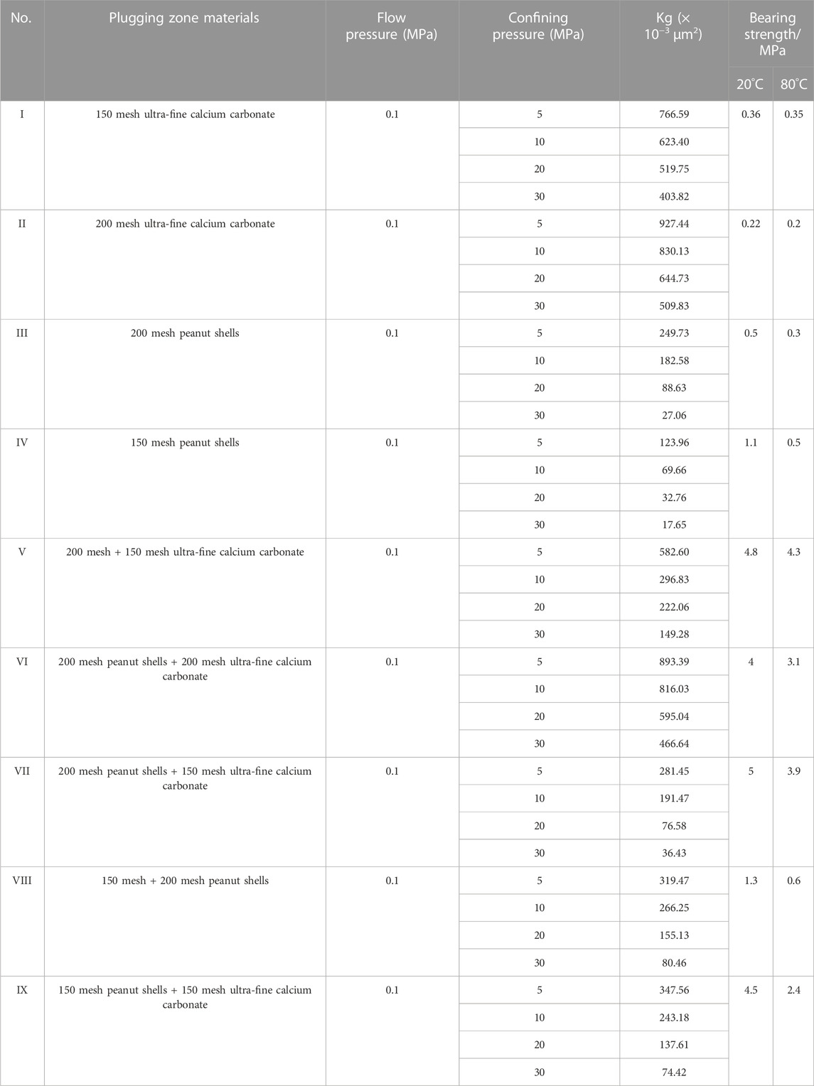
TABLE 2. Permeability and bear strength results of different plugging zones under variable confining pressure.
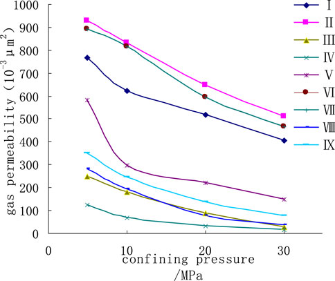
FIGURE 6. Permeability change of each plugging formula under variable confining pressure.
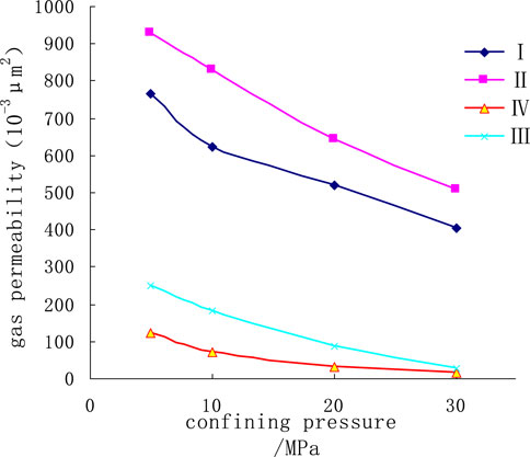
FIGURE 7. Permeability change of single plugging material plugging layer with variable confining pressure.
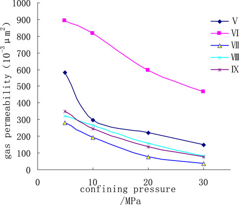
FIGURE 8. Permeability change of two-component plugging material under variable confining pressure.
In summary, the experimental results suggest that the combination of 150 mesh calcium carbonate particles and 200 mesh walnut shells yields the best sealing. This can be attributed to the fact that rigid 150 mesh calcium carbonate particles perfectly match the fracture width and small 200 mesh walnut shell particles deform under pressure, resulting in the lowest permeability and best sealing. In addition, we find that the permeability of rigid granular packing layers changes only modestly due to the small deformations involved, and that the fracture permeability can be lower with smaller calcium carbonate particles than with larger ones.
2.4 Micro analysis of temporary plugging layer
(1) Micro state of temporary plugging agent
The temporary plug of the artificial nucleus was observed by scanning electron microscopy (Figure 9). The results show that the temporary plug effectively adhered to and blocked off all pores, without any open pores observed at a magnification of 1,500, indicating its strong ability to block pores. This could potentially have significant implications for the development of new methods to improve the stability and functionality of artificial nuclei, but further studies are needed to fully understand its potential applications. Overall, this experiment provides valuable insights into efficient blocking capabilities. The use of temporary plugs for artificial nuclei warrants further investigation.
(2) Adhesion of temporary plugging agent to wall surface under pressure
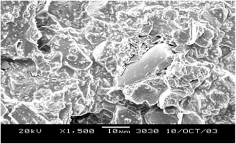
FIGURE 9. Electron microscope scanning image of artificial core temporary plugging agent.
As shown in Table 3, under the condition of 5 MPa ring pressure, after 30 min, the separation pressure of the temporary plugging agent from the fracture wall was 4.0 N by using the method of removing pieces.
(3) Deformation and elongation capacity of temporary plugging agent under pressure, as shown in Table 4

TABLE 3. Adhesion between temporary plugging agent and wall under pressure.

TABLE 4. Deformation and elongation capacity of temporary plugging agent under pressure.
3 Stability evaluation of temporary plugging layer
3.1 Performance evaluation method
3.1.1 Evaluation method of temporary plugging effect
Existing evaluation methods for temporary plugging agents are mainly formulated based on the process characteristics of water plugging, profile control of water injection wells, and drilling fluids for oil and gas wells. However, they are not fully applicable to the reservoir reconstruction process because there is no uniform evaluation standard or recognized method for temporary plugs for domestic and international reservoir reconstruction. To address this, a new evaluation method for temporary plugging agents in reservoir reconstruction is proposed in this paper, focusing on the temporary plugging ability and plugging removal performance of the temporary plugging agent.
The temporary plugging agent is used to temporarily plug high permeability layers or fractures to create a plugging layer, which forces the subsequent injected liquid into the low permeability layer or creates a new fracture. After the operation, the plugging layer can be dissolved/degraded under the formation conditions to remove the temporary plugging agent. To evaluate temporary plugging agents, the temporary plug rate and fracture pressure at the reservoir temperature are investigated to determine the properties of the temporary plug on fracture, matrix, and other reservoirs. Additionally, the high-temperature solubility/degradability of the temporary plug is evaluated to determine if the temporary plugging agent will cause damage to the reservoir after being removed.
The evaluation of the temporary plug rate and break pressure can be achieved through core flow devices. When evaluating the temporary plug rate, the percentage decrease in permeability after the temporary plug with a temporary plugging agent should be calculated. The break pressure of a temporary plug is the lowest pressure at which the reservoir reconstruction fluid can break through a temporary plug layer of a certain thickness, indicating the pressure at which the reservoir reconstruction fluid cannot penetrate the temporary plug layer in large quantities.
In conclusion, the proposed evaluation method for temporary plugging agents in reservoir reconstruction focuses on the temporary plugging ability and plugging removal performance of the temporary plugging agent. Through the evaluation of the temporary plug rate and break pressure, the properties of the temporary plug on fracture, matrix, and other reservoirs, as well as the high-temperature solubility/degradability of the temporary plug, can be determined more accurately and effectively.
(1) Experimental condition
The experimental conditions are shown in Table 5 below.

TABLE 5. Experimental condition.
(2) Experimental methods (Figure 10)
Breakthrough pressure after temporary plugging of matrix:
A. Measure the initial permeability of the core by using standard saline solution at 80°C, regardless of temperature effects on permeability.
B. To achieve complete wetting, add an appropriate amount of reservoir conversion liquid until completely mixed with the temporary blocking agent.
C. Fill the core’s front end with a wetted temporary blocking solution of some thickness.
D. Inject standard brine at a constant flow rate (10 mL/min) into the end face of the core filled with temporary blocking solution. Record the following parameters: displacement time, flow rate, pressure, and liquid volume at the outlet.
E. If the core does not break after increasing the displacement pressure to 40 MPa, switch on constant pressure control and continue injecting standard brine while observing stability.
F. The experiment concludes when there is a sudden decrease in pressure (usually over 30%) or a sudden increase in liquid flow at the outlet (usually over 30%), indicating core breakthrough.
G. Remove the core and examine it to conclude the experiment.
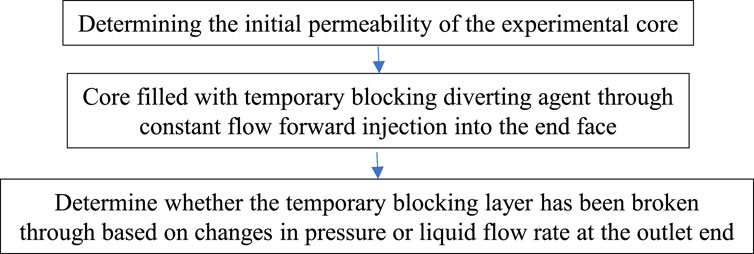
FIGURE 10. Experimental process.
Breakage pressure after temporary plugging of the fracture.
To measure the rupture pressure of the temporary plug diverter on the fracture, the artificial core was first split in half along the central axis. A layer of Teflon of a certain thickness is then applied to the edges of the split core, which is reassembled to mimic the formation of a fracture. Finally, the breakthrough pressure is measured according to the experimental method of temporary plugging of the matrix.
The temporary blockage rate is calculated according to the following formula:
Where,
3.1.2 Evaluation method for degradability of temporary plugging agent
The temporary plug in the reservoir reconstruction plays a crucial role in this process. This is necessary in order for the temporary plug not to dissolve or slowly dissolve when injected into the formation with the reservoir reconstruction fluid. A temporary stop should act as a torsion by bridging, expanding, and performing other functions to temporarily block the fracture or pore of the reservoir, thus forcing the subsequent reservoir reconstituted fluid into a low permeability layer or secondary sweet spot region. Later, under the influence of the reservoir temperature and the fluid, the temporary plug will gradually dissolve or degrade to remove the plug. It is therefore necessary to assess the solubility of the temporary plug, mainly by investigating its dissociation in water at different temperatures.
(1) Experimental condition
Experimental equipment: thermostatic drying oven, high-temperature aging tank (with PTFE inner cylinder), which can be heated to 150°C.
Test temperature: 150°C. Test time: 4 h.
The experimental conditions are shown in Table 6 below.
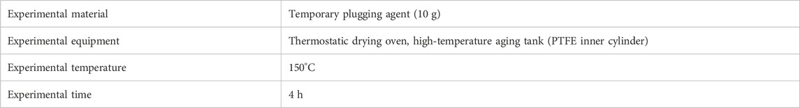
TABLE 6. Experimental condition.
(2) Experimental methods
To prepare the drilling fluid, 10 g of a temporary blocking agent is added to 200 mL of water, mixed vigorously, and poured into the aging tank. The mixture is then heated in a 150°C oven for 4 h, after which the tank is taken out of the oven and observed for any solid residue at the bottom.
3.2 Evaluation results
3.2.1 Evaluation of temporary plugging performance
Take a standard core with a permeability of 1.41 × 10⁻³ μm2 at 40 MPa, and connect an iron ring with a length of 1.0 cm at the end face. A temporary plug test is performed by adding a temporary plug to the iron ring. The injection rate is 10 mL/min. The pressure was first limited to 40 MPa to test the temporary plug rate and then increased to 50 MPa to test the maximum temporary plug pressure. The temporary plug test data before and after the optimization is shown in Table 7. Experimental results showed that while the pressure bearing capacity of the temporary plug did not improve significantly, its density did, and the flow rate of fluid through the sealing layer decreased from 0.73 to 0.07 mL/min. This improved performance not only reduces working fluid intrusion and prevents permeability damage to seals, but also reduces reservoir damage.
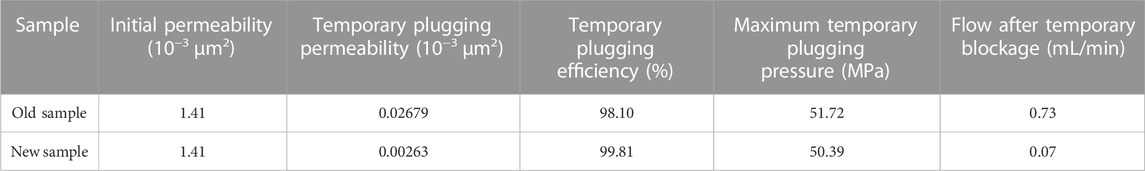
TABLE 7. Evaluation results and effects of temporary plugging experiment.
After the pressure rise to 50 MPa, the test was stopped due to the limitation of the core pressure resistance, and it can be seen that the temporary plugging rate of the new sample has been improved to a certain extent (Figure 11). From the appearance of the experimental results, a sealed layer of approximately 0.5 cm thickness can be seen at the end of the core.
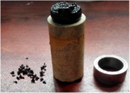
FIGURE 11. Temporary blocking test.
3.2.2 Evaluation of degradation ability of temporary plugging agent
(1) Thermal rolling treatment in drilling fluid
To prepare the temporary stopper, 10 g of the stopper was thoroughly mixed by hand with 200 mL of water before being added to the aging tank containing the drilling fluid. The mixture was then heated in an oven at 150°C for 4 h. The experimental results, shown in Figure 12, demonstrate that the agent completely dissolves, leaving no residue at the bottom of the tank. This successful application of a temporary blocking agent highlights its potential for use in future drilling applications.
(2) Acid resistance
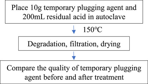
FIGURE 12. Experimental process.
The main equipment of the degradation experiment is a high-precision oven and autoclave with PTFE lining. During the experiment, put 10 g temporary plugging agent and 200 mL residual acid in an autoclave and put them in an oven at 150°C to degrade, filter, dry, and weigh the remaining temporary plugging agent mass Wd. The experimental steps are shown in Figure 12. The degradation rate = (10−Wd)/10% × 100%.
The evaluation results demonstrate that the temporary blocking material in the residual acid can achieve a degradation rate of more than 98% within 12 h with minimal damage to the reservoir, thus meeting the requirements. The degraded material left no solid residue and did not contaminate the reservoir. When particle impingement optimization is employed, the impingement rate is improved from 98.10% to 99.81%, and the maximum impingement pressure is increased to 50.39 MPa. Also, it can fully degrade at 150°C for 4 h, satisfying all design performance requirements.
4 Summary
(1) For temporary plugging, different temporary plug materials were tested for their ability to form a denser temporary plug layer. It has been shown that walnut-shell particles have a smaller permeability than coated hyperfine CaCO3, and that the denser the temporary plug layer, the better the particle size agrees with the fracture width.
(2) Mixing the coated hyperfine CaCO3 with the walnut shell resulted in a lower permeability of the temporary plug layer. In addition, the temporary plug layer formed from the multi-component temporary plug material is more compact and stable under variable confining pressure, thus allowing for better temporary plugging of fractures.
(3) The best results were obtained by coating hyperfine CaCO3 with walnut-shell particles, yielding a temporary plug layer with little change in permeability under variable confining pressure conditions and strong pressure bearing capacity. Experimental optimization of the two temporary plug materials resulted in a 2:1–3:1 mixing ratio of coated hyperfine CaCO3 and walnut-shell particles with particle sizes 2–3 times the fracture width. The temporary plugging rate increased from 98.10% to 99.81% with a maximum temporary plugging pressure of 50.39 MPa, which could be completely reduced at 150°C for 4 h. To some extent, this satisfies the temporary plugging technical requirements of “dense temporary plugging, two-way pressure bearing, low damage degradation.”
Data availability statement
The original contributions presented in the study are included in the article/Supplementary Material; further inquiries can be directed to the corresponding authors.
Author contributions
ZC: Conceptualization, funding acquisition, project administration, resources, writing—original draft and software. GW and CA: Data curation, formal analysis, and methodology. SL: writing—original draft, and writing—review and editing. XK: Project administration and resources. AZ: Investigation, methodology, software, and visualization. XX and JW: Conceptualization, funding acquisition, and methodology. XK: Investigation, methodology, and project administration. All authors contributed to the article and approved the submitted version.
Funding
This research was funded by “Research on offshore large-scale fracturing engineering technology (KJGG2022-0704), Key parameter characterization and dessert area evaluation technology of coalbed methane geological engineering (KJGG2022-1001), and Research on Inter-well Disturbance Integral Fracturing Technology of Coalbed Gas (2021-YXKJ-010).”
Acknowledgments
The authors are grateful to the reviewers and editors for their careful review of this manuscript.
Conflict of interest
Authors ZC, GW, JZ, CA, AZ, XX, and JW were employed by CNOOC Research Institute Co., Ltd.
The remaining authors declare that the research was conducted in the absence of any commercial or financial relationships that could be construed as a potential conflict of interest.
Publisher’s note
All claims expressed in this article are solely those of the authors and do not necessarily represent those of their affiliated organizations, or those of the publisher, the editors and the reviewers. Any product that may be evaluated in this article, or claim that may be made by its manufacturer, is not guaranteed or endorsed by the publisher.
References
1. Yan F, Kang Y, Li S, Du C, Li D. Simulated experiment on stress sensitivity in fractured-vuggy reservoir. Nat Gas Geosci (2010) 21(3):489–93.
2. Li S, Kang Y, Li D, You L, Lian Z. ANSYS simulation of fracture width variation in fracture-cavity reservoirs. Nat Gas Geosci (2011) 22(2):340–6.
3. Kang Y, Yan F, You L, Du C, Li D. Loss and control in regular reservoir formations in block Tahe. Drilling Fluid & Cementing Fluid (2010) 27(1):41–3.
4. Chen S, Kang Y, Ma X. Application of the screen bridging technology on the new drilling area. Drilling Prod Technol (2005) 28(6):99–101.
5. You L, Kang Y, Chen Y, Hao S, Cheng Q. Application of temporary and shielding plugging technology to improve well-logging responses for tight sandstone gas reservoir. Oil Drilling Prod Technol (2007) 29(1):113–7.
6. Okere CJ, Su G, Zheng L, Cai Y, Li Z, Liu H. Experimental, algorithmic, and theoretical analyses for selecting an optimal laboratory method to evaluate working fluid damage in coal bed methane reservoirs. Fuel (2020) 282:118513. doi:10.1016/j.fuel.2020.118513
7. He J, Okere CJ, Su G, Hu P, Zhang L, Xiong W, et al. Formation damage mitigation mechanism for coalbed methane wells via refracturing with fuzzy-ball fluid as temporary blocking agents. J Nat Gas Sci Eng (2021) 90:103956. doi:10.1016/j.jngse.2021.103956
8. Yan Z, Okere CJ, Zeng X, Yao Z, Su G, Gan M, et al. Preventing sour gas kicks during workover of natural gas wells from deep carbonate reservoirs with anti-hydrogen sulfide fuzzy-ball kill fluid. Energ Sci Eng (2022) 10(8):2674–88. doi:10.1002/ese3.1158
9. Okere CJ, Sheng JJ, Fan L, Huang X, Zheng L, Wei P. Experimental study on the degree and damage-control mechanisms of fuzzy-ball-induced damage in single and multi-layer commingled tight reservoirs. Pet Sci (2023). doi:10.1016/j.petsci.2023.05.017
10. Kang Y, You L, Xu X, Liao Z. Practices of formation damage control for deep fractured tight gas reservoir in Western Sichuan basin. In: Proccedings of the CPS/SPE International Oil & Gas Conference and Exhibition in China; June 2010; Beijing, China (2010). doi:10.2118/131323-MS
11. Moghadasi J, Jamialahmadi M, Müller-Steinhagen H, Sharif A. Formation damage due to scale formation in porous media resulting from water injection. In: SPE: 86524 presented at SPE International Symposium and Exhibition on Formation Damage Control held in Lafayette; February 2004; Louisiana (2004). doi:10.2118/86524-MS
12. Collins N, Kharitonov A, Whitfill D, Miller M. Comprehensive approach to severe lost circulation problems in Russia. In: Proccedings of the SPE Russia Oil & Gas Technical Conference and Exhibition held in Moscow; October 2010; Russia (2010). p. 26–8. doi:10.2118/135704-MS
13. Cui Y. A new method for the optimal selection of temporary plugging particles. Geoscience (2000) 14(1):91–4.
14. Qian Z, Lu Z, Bai H, Li J, Guan J. Leak resisting and plugging techniques for oil-based drilling fluid. Pet Geology oilfield Develop Daqing (2017) 36(6):101–4. doi:10.19597/J.ISSN.1000-3754.201610058
15. Xu CY, Zhang HL, Kang YL, Zhang J, Bai Y, Zhang J, et al. Physical plugging of lost circulation fractures at microscopic level. Fuel (2022) 317:123477. doi:10.1016/j.fuel.2022.123477
16. Xu CY, Zhang HL, She JP, Jiang G, Peng C, You Z. Experimental study on fracture plugging effect of irregular-shaped lost circulation materials. Energy (2023) 276:127544. doi:10.1016/j.energy.2023.127544
17. Abrams A. Mud design to minimize rock impairment due to particle invasion. JPT (1977) 29(2):586–92. doi:10.2118/5713-pa
18. Luo P. A temporary plugging technique on formation damage control during drilling and completion. Beijing: Encyclopedia of China Publishing House (1997). p. 68–98.
19. Zhang J, Yan J, Zhao H. Optimization of bridging particle size distribution of drilling fluid for formation protection. Drilling Fluid & Cementing Fluid (2004) 21(5):4–7.
20. Liu J, Kang Y, Liu D, You L, Gao B. Research on the temporary shielding plugging experiment in considering fracture-pore reservoir of fracture width and pressure difference. Drilling Prod Technol (2006) 29(2):97–8.
21. Yang J, Kang Y, Lan L, Hu Y, Chen J. Study of shielding temporary plugging technology for the fractured sandstone reservoir protection in the center of Sichuan basin. Drilling Fluid & Cementing Fluid (2006) 23(4):25–7.
22. Yan F, Kang Y, Sun K, Zhang J, Wang H. The temporary sealing formula for fractured-vuggy carbonate reservoir. Pet Drilling Tech (2012) 40(1):47–51.
23. Bao D, Qiu Z, Qiu W, Wang B, Guo B. Experiment on properties of lost circulation materials in high temperature formation. Acta Petrolei Sinica (2019) 40(7):846–57. doi:10.7623/syxb201907009
24. Fang J, Zhang Y, Li S, Yu P, Li Y. Acid-soluble temporary plugging technology for ultra-deep fractured carbonate reservoirs in block 1 of the Shunbei area. Pet Drilling Tech (2020) 48(2):17–22.
25. Addagalla AK, Jadhav P, Yadav P, Sarmah P, Maley I, Anerao A. A novel phase transition loss circulation solution for severe losses scenario: Case histories from the Middle East and africa. In: Proceedings of the SPE Asia Pacific Oil & Gas Conference and Exhibition; November, 2020; Virtual (2020). doi:10.2118/202234-MS
26. Vickers S, Cowie M, Jones T, Twynam AJ. A New methodology that surpasses current bridging theories to efficiently seal a varied pore throat distribution as found in natural reservoir formations. Wiertnictwo, Nafta, Gaz (2006) 23(1):501e515.
27. Alsaba M, Nygaard R, Hareland G, Contreras O. Review of lost circulation materials and treatments with an updated classification. In: Proceedings of the prepared for presentation at the 2014 AADE Fluids Technical Conference and Exhibition; April 2017; Houston, Texas (2014).
28. Nasiri A, Ghaffarkhah A, Moraveji MK, Ali G, Valizadeh M. Experimental and field test analysis of different loss control materials for combating lost circulation in bentonite mud. J Nat Gas Sci Eng (2017) 44:1875–5100. doi:10.1016/j.jngse.2017.04.004
29. Bao D, Qiu Z, Zhao X, Zhong H, Chen J, Liu J. Experimental investigation of sealing ability of lost circulation materials using the test apparatus with long fracture slot. J Pet Sci Eng (2019) 183:106396. doi:10.1016/j.petrol.2019.106396
30. Souza TM, Filho MNB, Calçada LA, Scheid CM. Evaluation of the effect of temperature and pressure on the process of combating loss of circulation using fibrous and granular materials. J Pet Sci Eng (2022) 219:111115. doi:10.1016/j.petrol.2022.111115
31. Luo Y, Zhang Y, Yang Z, Chang L, Zhang J. Application of temporary plugging and acidization in Changqing low permeability reservoirs. Chem Eng Oil Gas (2008) 37(3):229–32.
32. Xiong Y, Xueqin Z, Long S. Research and application of a new type of temporary plugging diverting agent for reservoir reconstruction. Chem Eng Oil Gas (2017) 46(2):59–67.
33. Wang Y, Zhou C, Yi X, Li L, Chen W, Han X. Technology and application of segmented temporary plugging acid fracturing in highly deviated wells in ultradeep carbonate reservoirs in southwest China. ACS omega (2020) 5(39):25009–15. doi:10.1021/acsomega.0c01008
34. Wang Y, Fan Y, Zhou C, Luo Z, Chen W, He T, et al. Research and application of segmented acid fracturing by temporary plugging in ultradeep carbonate reservoirs. ACS omega (2021) 6(43):28620–9. doi:10.1021/acsomega.1c03021
35. Lu Z. Progress and prospect study on temporary plugging agent for diverting fracturing[J]. Sci Technol Eng (2020) 20(31):12691–701.
36. Li S, Zhang H, Wang M, Zhang X, Zhou C, Hu Q. Experimental investigation into temporary acidizing of fractured Carbonate reservoirs in Sichuan Basin. Chem Eng Oil Gas (2021) 50(3):90–5.
Keywords: temporary blockage, temporary plugging layer, pressure bearing capacity, degradation, permeability
Citation: Chen Z, Wu G, Zhou J, Ai C, Zhang A, Xie X, Wu J, Kong X and Li S (2023) Optimization of degradable temporary plugging material and experimental study on stability of temporary plugging layer. Front. Phys. 11:1167215. doi: 10.3389/fphy.2023.1167215
Received: 16 February 2023; Accepted: 11 July 2023;
Published: 21 August 2023.
Edited by:
Chong Lin, CCDC Drilling & Production Technology Research Institute, ChinaReviewed by:
Jiajia Bai, Changzhou University, ChinaJun Li, Southwest Petroleum University, China
Chinedu J. Okere, Texas Tech University, United States
Mingzheng Yang, Louisiana State University, United States
Copyright © 2023 Chen, Wu, Zhou, Ai, Zhang, Xie, Wu, Kong and Li. This is an open-access article distributed under the terms of the Creative Commons Attribution License (CC BY). The use, distribution or reproduction in other forums is permitted, provided the original author(s) and the copyright owner(s) are credited and that the original publication in this journal is cited, in accordance with accepted academic practice. No use, distribution or reproduction is permitted which does not comply with these terms.
*Correspondence: Jun Zhou, emhvdWp1bjIzQGNub29jLmNvbS5jbg==; Xiangwei Kong, NTAxMDc0QHlhbmd0emV1LmVkdS5jbg==