 Weiwei Fan
 Huagan Wu
 Quan Xu
- School of Microelectronics and Control Engineering, Changzhou University, Changzhou, China
Electromagnetic induction can effectively induce abundant firing patterns in neurons. In modeling a neuron model with the electromagnetic induction effect, an electromagnetic induction current is frequently added to the state equation of membrane potential. To more properly reflect the non-uniform distribution of the ions inside and outside the neuron membrane, an ideal flux-controlled memristor with sinusoidal memductance function and non-linearly modulated input is raised to depict an electromagnetic induction effect on a Hindmarsh–Rose neuron model, and thereby, a three-dimensional (3D) memristive Hindmarsh–Rose (mHR) neuron model is built in this paper. The proposed mHR neuron model possesses no equilibrium point since the involvement of the ideal flux-controlled memristor, which induces the generation of hidden dynamics. Numerical results declare that the mHR neuron model can generate abundant hidden dynamics, i.e., periodic spiking, chaotic spiking, period-doubling bifurcation route, tangent bifurcation, and chaos crisis. These hidden dynamics are much related to the memristor coupling strength and externally applied stimulus. Afterward, the memristor initial condition-offset boosting behavior is revealed. This can trigger the generation of infinite multiple coexisting firing patterns along the memristor variable coordinate. These coexisting firing patterns have identical attractor topology but different locations in the phase plane. Finally, an analog circuit is designed for implementing the mHR neuron model, and PSIM-based circuit simulation is executed. The circuit-simulated results perfectly verify the generation of hidden infinite multiple coexisting initial condition-offset boosting firing patterns in the proposed mHR neuron model.
1 Introduction
The nervous system contains a huge number of biological neurons, which are the basic information handling and integrating units of a biological nervous system [1]. The dynamical properties of these biological neurons are crucial for determining the behaviors of the nervous systems [2, 3]. Thus, modeling of the biological neuron and exploring its dynamical behaviors are research hotspots and attract many researchers’ attention. Up to date, numerous neuron models have been constructed to depict different kinds of biological neurons, and they can roughly be divided into two categories, i.e., the continuous-time neuron model [4–10] and discrete-time map [11–13]. In the literature, some of the continuous-time neuron models were built based on the electrophysiological ion transport mechanism [4–7]. In addition, some continuous-time neuron models [8–10] and discrete-time maps [11, 13] were built on dynamical assumptions to reproduce electrical activities without regard to the neuron structure [14]. No matter which category they are, all these neuron models can effectively reproduce abundant firing patterns in response to the change of the electrophysiological environment. Recently, the electromagnetic induction effect has immersed great scientists’ concern, which can greatly affect the neuron dynamics [15–17] and neural network behaviors [18, 19].
Actually, the media of a biological neuron can be magnetized during its polarizing and depolarizing processes [20]. On one hand, periodic firing can control the transition, pumping, and distribution of calcium, potassium, chloride, etc., ions in these processes. On the other hand, the distribution, pumping, and transition of these ions can induce fluctuation of the membrane potential. Meanwhile, the electromagnetic induction effect is induced when the ions pass through the neuron membrane. Thus, ion channel currents and the electromagnetic induction current simultaneously affect the membrane potential. In the literature, flux-controlled memristors were used in various neuron models to depict the dynamic relation between the membrane potential and magnetic flux [21]. In other words, the flux-controlled memristors were used in the Hodgkin–Huxley neuron model [22–24], Izhikevich neuron model [25], FitzHugh–Nagumo neuron model [26], and three-dimensional (3D) [27–31]/two dimensional (2D) [32–34] Hindmarsh–Rose neuron model to depict the electromagnetic induction effect. These memristive neuron models can generate abundant firing patterns since the involvement of the flux-controlled memristor. To explain in detail, these flux-controlled memristors are non-ideal with a quadratic polynomial memductance function [22–30, 32, 33] and ideal with hypertangent/sinusoidal/cosinoidal memductance functions [20, 31, 33]. It is worth noting that the state equations of these memristors are linearly controlled by a membrane potential. Actually, the membrane potential possesses non-linear regulation on magnetization since the non-uniform distribution of the ions inside and outside the neuron membrane. To stress this issue, an ideal flux-controlled memristor with a sinusoidal memductance function and non-linear modulation on a memristor magnetic flux is raised to availably depict the electromagnetic induction effect in this paper.
The Hindmarsh–Rose neuron model is a simple kind of neuron model built on dynamical assumptions, which can reproduce main firing patterns of the biological neuron [9]. In the literature, the memristive Hindmarsh–Rose (mHR) neuron models with ideal memristors can easily generate multistability with coexisting firing patterns. In this case, the mHR neuron model has no equilibrium point, which induces the occurrence of hidden dynamics [20]. In particular, the initial condition-offset boosting behavior is triggered since the involved ideal flux-controlled memristor possessing sinusoidal/cosinoidal memductance functions [20, 34, 35], which is very different from the parameter-offset boosting behavior [36–38]. This induces the occurrence of extreme multistability with infinite multiple coexisting firing patterns. These coexisting firing patterns own attractors having identical topology and boosting along the memristor variable coordinate [20, 34]. Herein, a mHR neuron model with our proposed memristor is tamed for simplicity but without losing generality. The hidden dynamics and initial condition-offset boosting behavior of the mHR neuron model are investigated by numerical simulation and PSIM-based circuit simulation in this paper. A brief comparison between some aforementioned mHR neuron models and the model reported in this paper is demonstrated in Table 1. It is demonstrated that the memristor employed in building the mHR neuron model in this paper is different from the memristors reported in the aforementioned literature works. The electromagnetic induction effect characterized by the memristor is established by considering the periodic magnetization processing and non-uniform distribution of the ions inside and outside the neuron membrane.
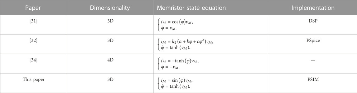
TABLE 1. Comparison of relevant papers on the mHR neuron models.
The remainder of this paper is formulated as follows: Section 2 explains the building of a mHR neuron model with hidden dynamics. Section 3 explains memristor parameter- and stimulus parameter-related dynamical distributions and bifurcation behaviors by numerical simulations. Section 4 explains the memristor initial condition-offset boosting behavior and infinite multiple coexisting firing patterns. Section 5 explains the analog circuit design and PSIM-based circuit simulation. Finally, Section 6 briefly concludes the main results of this paper.
2 Memristive Hindmarsh–Rose neuron model
Considering the periodic magnetization process and non-linear regulation of electromagnetic induction, a memristor with sinusoidal memductance function and non-linearly modulated input is raised, which is mathematically expressed as follows:
where vM and iM represent the terminal voltage and current, respectively. W(φ) = sin(φ) is the periodic memductance function, and magnetic flux φ is the memristor inner state variable. Different from the memristor reported in [20], this memristor has a non-linearly modulated input, i.e., a hypertangent function, to reflect the non-uniform distribution of the ions inside and outside the neuron membrane. The hypertangent function is continuously derivable and bounded above and below.
To investigate this kind of electromagnetic induction effect on a neuron, the memristor is introduced into the existing 2D Hindmarsh–Rose neuron model [9]; thereby, a 3D mHR neuron model is built as follows:
where x is the membrane potential and y is the recovery variable. a, b, c, and d are four controllable parameters in the original model [39]. I is the externally applied stimulus, and k is the coupling strength of electromagnetic induction. We mainly consider the dynamical effect of the externally applied stimulus I and coupling strength k on the mHR neuron model in the following sections. Therefore, the four controllable parameters, namely, a = 1, b = 3, c = 1, and d = 5, are assigned as the original parameters in [39, 40]; I and k are adjustable parameters with positive values, and their typical values are preset to I = 1.5 and k = 2.
By setting the left sides of (2) equal to 0, one can obtain the following equation:
Evidently, there is no solution of (3) since I has a positive value. In other words, model (2) has no equilibrium point. Therefore, the dynamical behaviors and firing patterns generated by the 3D mHR neuron model (2) are hidden [41].
3 Parameter-related hidden dynamics
In this section, we mainly focus our concern on the parameter-related hidden dynamics with the two adjustable parameters of the coupling strength k and externally applied stimulus I. The initial conditions [x(0), y(0), φ(0)] = [0, 0, 0] are utilized. The MATLAB-based ODE45 algorithm with a fixed time-step duration of 10−2 s and time-end duration of 800 s is utilized to calculate the bifurcation diagram, and the Jacobi matrix-based Wolf’s method with a time-step duration of 0.1 s and time-end duration of 4,000 s is employed to calculate Lyapunov exponent spectra [42].
3.1 Dynamical distribution
When the two adjustable parameters k and I are varied in 0.5 ≤ k ≤ 3 and 0 ≤ I ≤ 3, dynamical distributions of the bifurcation diagram and dynamical map in the k–I parameter plane are simulated, as shown in Figure 1. The 2D bifurcation diagram is depicted by checking the periodicities of the membrane potential x, as shown in Figure 1A, that is, the trajectories with different periodicities are painted by different colors. The red marked by CH represents chaos, and the other colors represent period-1 to period-8 marked by P1 to P8, respectively. One can see that the 2D bifurcation diagram possesses a ribbon structure in some regions and the ribbons marked by P1, P2, P4, and P8 appear in sequence. Also, numerous ribbons marked by P3, P5, and P7 are embedded in the CH (red) region or near the neighborhood of the CH region. These declare that numerous periodic windows generated via tangent bifurcations [42] and period-doubling bifurcations [29] are triggered by varying the two parameters. In addition, the 2D dynamical map described by the largest Lyapunov exponent (LLE) is employed to depict the parameter-related dynamical distribution in the k–I parameter plane, as shown in Figure 1B. The colorized domains are painted with different colors according to the values of LLE: red for chaos with positive LLE and other colors for a period with negative LLE.
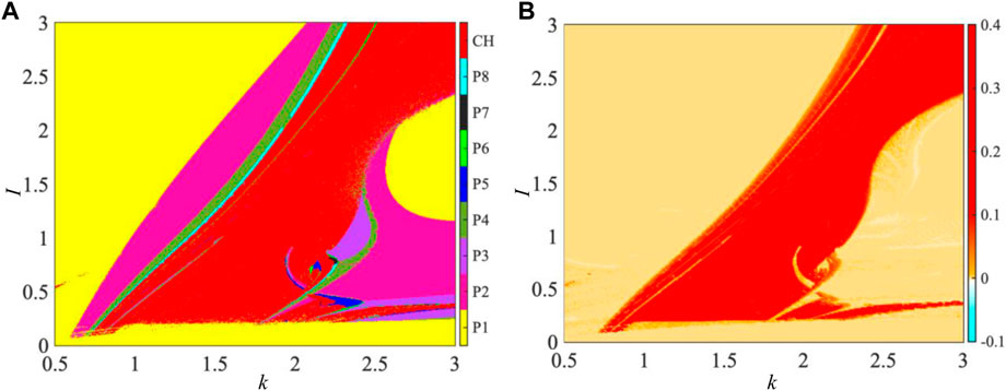
FIGURE 1. Parameter-related dynamical distribution in the k–I parameter plane for a = 1, b = 3, c = 1, and d = 5 under the initial conditions [x(0), y(0), φ(0)] = [0, 0, 0]. (A) 2D bifurcation diagram depicted by inspecting periodicities of the membrane potential x and (B) 2D dynamical map described by LLE.
It is demonstrated that the dynamical behaviors depicted by dynamical distributions of the 2D bifurcation diagram and 2D dynamical map are completely identical. These numerical results demonstrate that the coupling strength and externally applied stimulus can induce abundant dynamical behaviors on neuron properties of the 3D mHR neuron model.
3.2 Bifurcation behavior
To more clearly demonstrate the bifurcation behaviors with the coupling strength k and externally applied stimulus I, the one-dimensional (1D) bifurcation diagram and Lyapunov exponent spectra (LEs) are numerically simulated with the variations of k and I, as shown in Figures 2A, B, respectively. The representations at the top of Figures 2A, B display the 1D bifurcation diagrams of the membrane potential x, while the representations at the bottom exhibit LEs.
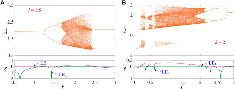
FIGURE 2. Parameter-related bifurcation behaviors as k and I changed in determined ranges for a = 1, b = 3, c = 1, and d = 5 under the initial conditions [x(0), y(0), φ(0)] = [0, 0, 0]. (A) k-related bifurcation diagram (top) and LEs (bottom) for I = 1.5 and (B) I-related bifurcation diagram (top) and LEs (bottom) for k = 2.
Herein, the externally applied stimulus I = 1.5 is fixed, and the coupling strength k is varied in 0.5 ≤ k ≤ 3. The 1D bifurcation diagram for the maximum value of the membrane potential x (marked as xmax) is depicted in Figure 2A. When k increases from 0.5, the trajectory of mHR neuron model (2) starts from period-1, then enters chaos via the forward period-doubling bifurcation route [29], returns to period-2 via tangent bifurcation [42], and ends up to period-1. It is worth noting that the period-doubling bifurcation route demonstrates the transition of P1-P2-P4-P8-CH. In Figure 2A, only the first Lyapunov exponent LE1 and partial second Lyapunov exponent LE2 are shown for better visualization since the third exponent is very small. The LE1 exponent has a zero value for periodic states with different periodicities and a positive value for the chaotic state. The LE2 exponent increases to zero and immediately returns to the negative value along with the occurrence of period-doubling bifurcations. It is observed that the bifurcation behaviors revealed by the 1D bifurcation diagram (up) are effectively verified by the LEs (bottom) in Figure 2A.
Then, we fix coupling strength k = 2 and change the externally applied stimulus I in 0 ≤ I ≤ 3. In Figure 2B, one can see that with the increase of I, the mHR neuron model undergoes period-1 to chaos via chaos crisis [43], to period-2 via tangent bifurcation, to chaos via forward period-doubling bifurcations, to period-3 via reverse period-doubling bifurcations, to chaos via chaos crisis, and finally to period-1 via reverse period-doubling bifurcations. It is worth noting that there exists a small periodic window near the neighborhood of I = 1.95. The LE1 exponent drops to zero and maintains in the narrow parameter range and then returns to a positive value with the appearance of a periodic window. Obviously, the evolution of LEs confirms the occurrence of bifurcation behaviors.
Consequently, these bifurcation behaviors can lead to the occurrence of abundant periodic firing patterns with different periodicities and a chaotic firing pattern in the 3D mHR neuron model and can be regulated by the memristor coupling strength and externally applied stimulus.
3.3 Hidden firing patterns
In this section, five values of coupling strength k with I = 1.5 are selected from Figure 2A to partially display the firing patterns emerged from the 3D mHR neuron model, as shown in Figure 3. Time–domain waveforms of the membrane potential x (left) and corresponding phase portraits in the φ–x phase plane (right) are demonstrated; they are period-1 spiking, period-2 spiking, period-4 spiking, period-8 spiking, and chaotic spiking for k = 1, 1.5, 1.6, 1.65, and 2, respectively. These numerical results further demonstrate that the 3D mHR neuron model can generate hidden firing patterns of periodic spiking behaviors with different periodicities and a chaotic spiking behavior. Moreover, the state transition (P1-P2-P4-P8-CH) of firing patterns confirms the generation of the period-doubling bifurcation route.
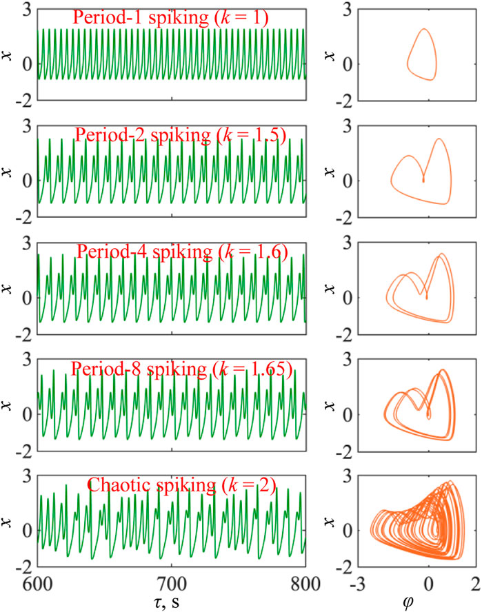
FIGURE 3. Time–domain waveforms (left) and phase portraits in the φ–x phase plane (right) with a = 1, b = 3, c = 1, d = 5, and I = 1.5 and the initial conditions [x(0), y(0), φ(0)] = [0, 0, 0] for k = 1 (period-1 spiking), k = 1.5 (period-2 spiking), k = 1.6 (period-4 spiking), k = 1.65 (period-8 spiking), and k = 2 (chaotic spiking), respectively.
4 Initial condition-related dynamics
Of particular interest, the 3D mHR neuron model (2) can show the initial condition-offset boosting behavior since the involvement of sinusoidal memductance function [20, 44]. This can trigger infinite multiple coexisting firing patterns for a fixed set of model parameters. In this section, we mainly focus our attention on this issue. Herein, we only consider the memristor initial condition-induced dynamical effect and set the initial conditions as [x(0), y(0), φ(0)] = [0, 0, φ(0)]. The numerical simulation settings are identical with those employed in Section 3.
4.1 Initial condition-offset boosting
Herein, two sets of model parameters, i.e., I = 1.5, k = 1.5 and I = 1.5, k = 2, are selected as paradigms to demonstrate the memristor initial condition-offset boosting behavior. The memristor initial condition is adjusted in the region [–20, 20]. The bifurcation plots of the 1D bifurcation diagram and Lyapunov exponent spectra for the two sets of model parameters are shown in Figures 4A, B, respectively.
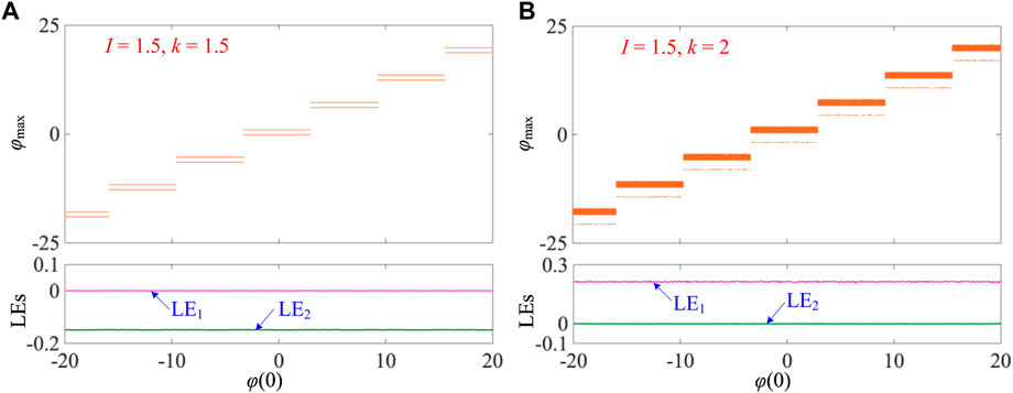
FIGURE 4. Memristor initial condition-offset boosting behaviors illustrated by 1D bifurcation plots of the 1D bifurcation diagram and LEs for the initial conditions [x(0), y(0), φ(0)] = [0, 0, φ(0)]. (A) I = 1.5 and k = 1.5 and (B) I = 1.5 and k = 2.
Figure 4A shows the bifurcation plots for I = 1.5 and k = 1.5, which demonstrates period-2 spiking firing patterns with the increase of the initial condition φ(0). One can see that the locations of these firing patterns possess a step-by-step structure and their dynamic amplitude is identical. In addition, the memristor initial condition applies at 2π initial condition-offset, which is the period of the sinusoidal memductance function sin(φ). In this case, the step change happens periodically. In addition, the LE1 and LE2 exponents demonstrate constant Lyapunov exponent spectra and are not related to the memristor initial condition, i.e., LE1 = 0 and LE2 = −0.15.
As shown in Figure 4B, the bifurcation plots for I = 1.5 and k = 2 are elaborated. The results also display the step-by-step memristor initial condition-offset boosting behavior; thereby, multiple coexisting chaotic firing patterns are generated. Also, the memristor initial condition applies at 2π initial condition-offset, and these steps periodically occur. Identically, the Lyapunov exponent spectra display constant values of LE1 and LE2 and possess LE1 = 0.21 and LE2 = 0 for the chaotic firing patterns. It is worth noting that the initial condition-offset boosting behavior exists for other firing patterns under different fixed model parameters. In addition, the memristor initial condition-offset boosting behavior can trigger infinite multiple coexisting firing patterns. We only demonstrate this behavior in a finite range of memristor initial conditions in this study.
4.2 Infinite multiple coexisting firing patterns
In the previous bifurcation analysis for the memristor initial condition-offset boosting behavior, the results display the occurrence of hidden infinite multiple coexisting firing patterns in the 3D mHR neuron model. To further demonstrate this striking memristor initial condition-offset boosting behavior, the coexisting firing patterns are displayed by the phase portrait in the φ–x phase plane, as shown in Figure 5. The coexisting period-2 spiking firing patterns for I = 1.5 and k = 1.5 under the initial conditions φ(0) = −18, −12, −6, 0, 6, 12, and 18 are shown in Figure 5A. These initial conditions are selected in each step from the bifurcation diagram in Figure 4A. The offsets among each of the two adjacent attractors of firing patterns are all 2π, and these attractors are not connected, which implies the emergence of initial condition-offset boosted attractors. The attractors possess identical topology but different locations. Similarly, the memristor initial condition-offset boosted coexisting chaotic firing patterns for I = 1.5 and k = 2 under the initial conditions φ(0) = −18, −12, −6, 0, 6, 12, and 18 are also demonstrated in Figure 5B. It is worth noting that we do not select the initial conditions with the interval 2π for their convenient setting in PSIM-based circuit simulation. These results demonstrate the generation of hidden infinite multiple coexisting firing patterns in our proposed 3D mHR neuron model.
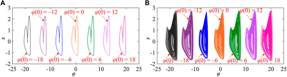
FIGURE 5. Infinite multiple coexisting firing patterns for different memristor initial conditions of φ(0) = −18 V, −12 V, −6 V, 0 V, 6 V, 12 V, and 18 V under different sets of model parameters. (A) Coexisting period-2 firing patterns for I = 1.5 and k = 1.5 and (B) coexisting chaotic firing patterns for I = 1.5 and k = 2.
5 Analog design and PSIM-based circuit simulation
The analog circuit design of neuron models is crucial for investigating the neuron dynamics and exploring neuron-based engineering applications [45, 46]. The 3D mHR neuron model can be easily designed by utilizing passive circuit components of a capacitor and resistor and the integrated chips of operational amplifier, multiplier, and trigonometric circuit modules. The circuit schematic representation is well-designed and given in Figure 6. The memristor equivalent circuit contains a hypertangent circuit module [47], a sinusoidal function chip U5, an operational amplifier U4, a multiplier M3, a capacitor, and two resistors, as shown in the bottom part of Figure 6. The main circuit involves two integrators, two multipliers, and an inverter, as shown in the top part of Figure 6. Then, the circuit state equations can be correspondingly built as follows:
where vx, vy, and vφ are three circuit state variables corresponding to the model variables x, y, and φ, respectively. We suppose C1 = C2 = C3 = C and the integral time constant RC = 1 ms, i.e., C = 100 nF and R = 10 kΩ. In addition, the recovery variable vy is linearly transformed to reduce its dynamic amplitude as follows:
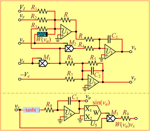
FIGURE 6. Circuit schematic representation of the 3D mHR neuron model.
The linear transformation is conducive to a hardware experiment since the value of the recovery variable approaches the saturation voltage of operational amplifiers without transformation. Thereby, the other circuit parameters are calculated as R1 = 10 kΩ, R2 = 1 kΩ, R3 = 3.3 kΩ, R4 = 10 kΩ, R5 = 10 kΩ, R6 = 20 kΩ, R7 = 100 kΩ, R8 = 10 kΩ, R9 = 3.3 kΩ, g1 = g2 = g3 = 1 V−1, and Vc = 1 V by comparing (2) with (4). It is worth noting that the two adjustable parameters can be regulated by I = VI and k = R/R9. The initial states of three capacitors are assigned as [vx(0), vy(0), vφ(0)] = [0 V, 0 V, vφ(0)].
Employing the circuit schematic representation illustrated in Figure 6, a PSIM-based simulation circuit is built and circuit parameters are accurately set. First, the two adjustable circuit parameters are set to VI = 1.5 V and R9 = 6.667 kΩ corresponding to I = 1.5 and k = 1.5. By respectively setting the memristor initial condition vφ(0) to −18 V, −12 V, −6 V, 0 V, 6 V, 12 V, and 18 V, PSIM-based circuit simulations are executed and phase trajectories are obtained in the vφ–vx phase plane, as shown in Figure 7A. Then, the two adjustable circuit parameters are set to VI = 1.5 V and R9 = 5 kΩ corresponding to I = 1.5 and k = 2. The PSIM-based circuit simulations are illustrated in Figure 7B. One can see that the PSIM-based circuit simulations in Figure 7 are very consistent with the numerical results in Figure 5. These circuit-simulated results manifest the occurrence of hidden infinite multiple coexisting initial condition-offset boosting firing patterns in our proposed 3D mHR neuron model. It is worth noting that the power supplies for operational amplifiers and multipliers are, respectively, set to ±30 V and ±15 V in PSIM-based circuit simulation.
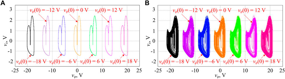
FIGURE 7. PSIM-based circuit simulation of infinite multiple coexisting firing patterns for different memristor initial conditions of φ(0) = −18 V, −12 V, −6 V, 0 V, 6 V, 12 V, and 18 V under the two sets of circuit parameters. (A) Coexisting period-2 firing patterns for VI = 1.5 V (I = 1.5) and R9 = 6.667 kΩ (k = 1.5) and (B) coexisting chaotic firing patterns for VI = 1.5 V (I = 1.5) and R9 = 5 kΩ (k = 2).
6 Conclusion
In this paper, an ideal flux-controlled memristor with sinusoidal memductance and non-linearly modulated input was presented to depict the electromagnetic induction effect in biological neurons. Then, the electromagnetic induction effect on an existing 2D Hindmarsh–Rose neuron model was elaborated. Theoretical analysis and numerical simulation demonstrated that the 3D mHR neuron model can generate the hidden memristor initial condition-offset boosting behavior with infinite multiple coexisting firing patterns. The attractors of these firing patterns have an offset along the memristor variable coordinate, and the offset is identical with the period of memductance function. In addition, PSIM-based circuit simulation further confirmed the validation of the analog circuit design and generation of the initial condition-offset boosting behavior. It is worth noting that the power supplies should be suitably set in PSIM-based circuit simulation to capture the offset boosting firing patterns. The settings can refer to the dynamic range for the attractors of these firing patterns along with the memristor variable coordinate. This hinders the hardware experimental measurement of initial condition-offset boosting firing patterns. In addition, it is not easy to accurately set the initial conditions in each step to acquire corresponding firing patterns from hardware experiments. However, the memristor initial condition-offset boosting firing patterns have potentiality in neuron-based engineering applications [37, 48], i.e., the waveform bias of chaotic signal and random signal generation [49]. These deserve our future concern.
Data availability statement
The original contributions presented in the study are included in the article/Supplementary Material; further inquiries can be directed to the corresponding author.
Author contributions
All authors listed have made a substantial, direct, and intellectual contribution to the work and approved it for publication.
Funding
This work was supported by the National Natural Science Foundation of China under grant nos 12172066 and 61801054, the Natural Science Foundation of Jiangsu Province, China, under grants BK20160282 and BK20210850, the Project 333 of Jiangsu Province, the Postgraduate Research and Practice Innovation Program of Jiangsu Province, China, under the grant no. KYCX22_3054, and the College Students’ Innovation and Entrepreneurship Training Program of Changzhou University.
Conflict of interest
The authors declare that the research was conducted in the absence of any commercial or financial relationships that could be construed as a potential conflict of interest.
Publisher’s note
All claims expressed in this article are solely those of the authors and do not necessarily represent those of their affiliated organizations, or those of the publisher, the editors, and the reviewers. Any product that may be evaluated in this article, or claim that may be made by its manufacturer, is not guaranteed or endorsed by the publisher.
References
1. Yao Z, Zhou P, Zhu ZG, Ma J. Phase synchronization between a light-dependent neuron and a thermosensitive neuron. Neurocomputing (2021) 423:518–34. doi:10.1016/j.neucom.2020.09.083
2. Zhu ZY, Wang RB, Zhu FY. The energy coding of a structural neural network based on the Hodgkin-Huxley model. Front Neurosci (2018) 12:122. doi:10.3389/fnins.2018.00122
3. Ji X, Hu XF, Zhou Y, Dong ZK, Duan SK. Adaptive sparse coding based on memristive neural network with applications. Cogn Neurodyn (2019) 13:475–88. doi:10.1007/s11571-019-09537-w
4. Hodgkin AL, Huxley AF. A quantitative description of membrane current and its application to conduction and excitation in nerve. Bull Math Biol (1990) 52:25–71. doi:10.1016/s0092-8240(05)80004-7
5. Chay TR. Chaos in a three-variable model of an excitable cell. Physica D (1985) 16:233–42. doi:10.1016/0167-2789(85)90060-0
6. Xu Q, Tan X, Zhu D, Bao H, Hu YH, Bao BC. Bifurcations to bursting and spiking in the Chay neuron and their validation in a digital circuit. Chaos Solitons Fractals (2020) 141:110353. doi:10.1016/j.chaos.2020.110353
7. Morris C, Lecar H. Voltage oscillations in the barnacle giant muscle fiber. Biophys J (1981) 35:193–213. doi:10.1016/s0006-3495(81)84782-0
8. FitzHugh R. Impulses and physiological states in theoretical models of nerve membrane. Biophys J (1961) 1:445–66. doi:10.1016/s0006-3495(61)86902-6
9. Hindmarsh JL, Rose RM. A model of the nerve impulse using two first-order differential equations. Nature (1982) 296:162–4. doi:10.1038/296162a0
10. Xu Q, Ju ZT, Ding ZT, Feng CT, Chen M, Bao BC. Electromagnetic induction effects on electrical activity within a memristive Wilson neuron model. Cogn Neurodyn (2022) 16:1221–31. doi:10.1007/s11571-021-09764-0
11. Elson RC, Selverston AI, Huerta R, Rulkov NF, Rabinovich MI, Abarbanel HDI. Synchronous behavior of two coupled biological neurons. Phys Rev Lett (1998) 81:5692–5. doi:10.1103/physrevlett.81.5692
12. Xu Q, Liu T, Ding SK, Wu HG, Huang LP, Chen B. Extreme multistability and phase synchronization in a heterogeneous bi-neuron Rulkov network with memristive electromagnetic induction. Cogn Neurodyn (2022). doi:10.1007/s11571-022-09866-3
13. Vivekanandhan G, Natiq H, Merrikhi Y, Rajagopal K, Jafari S. Dynamical analysis and synchronization of a new memristive Chialvo neuron model. Electronics (2023) 12:545. doi:10.3390/electronics12030545
14. Xu Q, Liu T, Feng CT, Bao H, Wu HG, Bao BC. Continuous non-autonomous memristive Rulkov model with extreme multistability. Chin Phys B (2021) 30:128702. doi:10.1088/1674-1056/ac2f30
15. Lv M, Ma J. Multiple modes of electrical activities in a new neuron model under electromagnetic radiation. Neurocomputing (2016) 205:375–81. doi:10.1016/j.neucom.2016.05.004
16. Lin HR, Wang CH, Deng QL, Xu C, Deng ZQ, Zhou C. Review on chaotic dynamics of memristive neuron and neural network. Nonlinear Dyn (2021) 106:959–73. doi:10.1007/s11071-021-06853-x
17. Shen H, Yu F, Wang CH, Sun JR, Cai S. Firing mechanism based on single memristive neuron and double memristive coupled neurons. Nonlinear Dyn (2022) 110:3807–22. doi:10.1007/s11071-022-07812-w
18. Yu F., Shen H., Yu Q. L., Kong X. X., Sharma P. K., Cai S. (2022). Privacy Protection of Medical Data Based on Multi-scroll Memristive Hopfield Neural Network. IEEE. Trans. Netw. Sci. Eng. 10 845–858.
19. Yu F, Kong XX, Mokbel AAM, Yao W, Cai S. Complex dynamics, hardware implementation and image encryption application of multiscroll memeristive Hopfield neural network with a novel local active memeristor. IEEE Trans Circuits Syst Express Briefs (2023) 70:326–30. doi:10.1109/tcsii.2022.3218468
20. Bao H, Liu WB, Ma J, Wu HG. Memristor initial-offset boosting in memristive HR neuron model with hidden firing patterns. Int J Bifurc Chaos (2020) 30:2030029. doi:10.1142/s0218127420300293
21. Du L, Cao ZL, Lei YM, Deng ZC. Electrical activities of neural systems exposed to sinusoidal induced electric field with random phase. Sci China Technol Sci (2019) 62:1141–50. doi:10.1007/s11431-017-9309-9
22. Wu FQ, Wang CN, Jin WY, Ma J. Dynamical responses in a new neuron model subjected to electromagnetic induction and phase noise. Physica A (2017) 469:81–8. doi:10.1016/j.physa.2016.11.056
23. Yuan ZX, Feng PH, Du MM, Wu Y. Dynamical response of a neuron-astrocyte coupling system under electromagnetic induction and external stimulation. Chin Phys B (2020) 29:030504.
24. Yuan ZX, Feng PH, Fang YC, Yu YY, Wu Y. Astrocytic modulation on neuronal electric mode selection induced by magnetic field effect. Cogn Neurodyn (2022) 16:183–94. doi:10.1007/s11571-021-09709-7
25. Kafraj MS, Parastesh F, Jafari S. Firing patterns of an improved Izhikevich neuron model under the effect of electromagnetic induction and noise. Chaos Solitons Fractals (2020) 137:109782. doi:10.1016/j.chaos.2020.109782
26. Jia YB, Lu B, Gu HG. Excitatory electromagnetic induction current enhances coherence resonance of the FitzHugh-Nagumo neuron. Int J Bifurc Chaos (2019) 33:1950242. doi:10.1142/s0217979219502424
27. Tang KM, Wang ZL, Shi XR. Electrical activity in a time-delay four variable neuron model under electromagnetic induction. Front Comput Neurosci (2017) 11:105. doi:10.3389/fncom.2017.00105
28. Lu LL, Jia Y, Xu Y, Ge MY, Yang LJ, Zhan X. Energy dependence on modes of electric activities of neuron driven by different external mixed signals under electromagnetic induction. Sci China Technol Sci (2019) 62:427–40. doi:10.1007/s11431-017-9217-x
29. An XL, Qiao S. The hidden, period-adding, mixed-mode oscillations and control in a HR neuron under electromagnetic induction. Chaos Solitons Fractals (2021) 143:110587. doi:10.1016/j.chaos.2020.110587
30. Rajagopal K, Jafari S, Karthikeyan A, Srinivasan A. Effect of magnetic induction on the synchronizability of coupled neuron network. Chaos (2021) 31:083115. doi:10.1063/5.0061406
31. Xu L, Qi GY, Ma J. Modeling of memristor-based Hindmarsh-Rose neuron and its dynamical analyses using energy method. Appl Mathemat Model (2022) 101:503–16. doi:10.1016/j.apm.2021.09.003
32. Hu XY, Wang S, Liu CX. Hidden coexisting firing patterns and bubble-like bifurcation in HR neuron model under electromagnetic induction. Chin J Phys (2022) 77:2541–9. doi:10.1016/j.cjph.2022.04.016
33. Njitacke ZT, Doubla IS, Mabekou S, Kengne J. Hidden electrical activity of two neurons connected with an asymmetric electric coupling subject to electromagnetic induction: Coexistence of patterns and its analog implementation. Chaos Solitons Fractals (2020) 137:109785. doi:10.1016/j.chaos.2020.109785
34. Zhang S, Zheng JH, Wang XP, Zeng ZG. A novel no-equilibrium HR neuron model with hidden homogeneous extreme multistability. Chaos Solitons Fractals (2021) 145:110761. doi:10.1016/j.chaos.2021.110761
35. Wu HG, Ye Y, Bao BC, Chen M, Xu Q. Memristor initial boosting behaviors in a two-memristor-based hyperchaotic system. Chaos, Solitons Fractals (2019) 121:178–85. doi:10.1016/j.chaos.2019.03.005
36. Wu HG, Zhou J, Chen M, Xu Q, Bao BC. DC-offset induced asymmetry in memristive diode-bridge-based Shinriki oscillator. Chaos Solitons Fractals (2022) 154:111624. doi:10.1016/j.chaos.2021.111624
37. Li CB, Wang X, Chen GR. Diagnosing multistability by offset boosting. Nonlinear Dyn (2017) 90:1335–41. doi:10.1007/s11071-017-3729-1
38. Li CB, Sprott JC. Aninfinite3-Dquasiperiodiclatticeofchaotic attractors. Phys Lett A (2018) 382:581–7. doi:10.1016/j.physleta.2017.12.022
39. Lakshmanan S, Lim CP, Nahavandi S, Prakash M, Balasubramaniam P. Dynamical analysis of the Hindmarsh-Rose neuron with time delays. IEEE Trans Neural Netw Learn (2017) 28:1953–8. doi:10.1109/tnnls.2016.2557845
40. Kaslik E. Analysis of two- and three-dimensional fractional-order Hindmarsh-Rose type neuronal models. Fract Calc Appl Anal (2017) 20:623–45. doi:10.1515/fca-2017-0033
41. Pham VT, Wang X, Jafari S, Volos C, Kapitaniak T. From Wang–Chen system with only one stable equilibrium to a new chaotic system without equilibrium. Int J Bifurc Chaos (2017) 27:1750097. doi:10.1142/s0218127417500973
42. Xu Q, Ding SK, Bao H, Chen M, Bao BC. Piecewise-linear simplification for adaptive synaptic neuron model. IEEE Trans Circuits Syst Express Briefs (2022) 69:1832–6. doi:10.1109/tcsii.2021.3124666
43. Bao H, Chen ZG, Cai JM, Xu Q, Bao BC. Memristive cycle three-neuron-based neural network with chaos and global coexisting attractors. Sci China Technol Sci (2022) 65:2582–92.
44. Wen JJ, Wang JP. A chaotic system with infinite attractors based on memristor. Front Phys (2022) 10:902500. doi:10.3389/fphy.2022.902500
45. He SB, Fu LX, Lu Y, Wu XM, Wang HH, Sun KH. Analog circuit of a simplified Tent map and its application in sensor position optimization. IEEE Trans Circuits Syst Express Briefs (2023) 1. doi:10.1109/tcsii.2022.3217674
46. Ding SK, Wang N, Bao H, Chen B, Wu HG, Xu Q. Memristor synapse-coupled piecewise-linear simplified Hopfield neural network: Dynamics analysis and circuit implementation. Chaos Solitons Fractals (2023) 166:112899. doi:10.1016/j.chaos.2022.112899
47. Xu Q, Chen XJ, Chen B, Wu HG, Li Z, Bao H. Dynamical analysis of an improved FitzHugh-Nagumo neuron model with multiplier-free implementation. Nonlinear Dyn (2023). doi:10.1007/s11071-023-08274-4
48. Kuznetsov AP, Kuznetsov SP, Mosekilde E, Stankevich NV. Coexisting hidden attractors in a radio-physical oscillator system. J Phys A Math Theor (2015) 48:125101. doi:10.1088/1751-8113/48/12/125101
Keywords: firing pattern, hidden dynamics, electromagnetic induction, memristor, analog implementation, Hindmarsh–Rose neuron model
Citation: Fan W, Chen X, Wang Y, Chen B, Wu H and Xu Q (2023) Hidden firing patterns and memristor initial condition-offset boosting behavior in a memristive Hindmarsh-Rose neuron model. Front. Phys. 11:1160419. doi: 10.3389/fphy.2023.1160419
Received: 07 February 2023; Accepted: 21 February 2023;
Published: 06 March 2023.
Edited by:
Hairong Lin, Hunan University, ChinaReviewed by:
Yan Liang, Hangzhou Dianzi University, ChinaSajad Jafari, Amirkabir University of Technology, Iran
Copyright © 2023 Fan, Chen, Wang, Chen, Wu and Xu. This is an open-access article distributed under the terms of the Creative Commons Attribution License (CC BY). The use, distribution or reproduction in other forums is permitted, provided the original author(s) and the copyright owner(s) are credited and that the original publication in this journal is cited, in accordance with accepted academic practice. No use, distribution or reproduction is permitted which does not comply with these terms.
*Correspondence: Quan Xu, eHVxdWFuQGNjenUuZWR1LmNu