- 1School of Information and Electrical Engineering, Hunan University of Science and Technology, Xiangtan, China
- 2Hunan key laboratory of the research and development of novel pharmaceutical preparations, Changsha Medical University, Changsha, China
As a powerful method for time-varying problems solving, the zeroing neural network (ZNN) is widely applied in many practical applications that can be modeled as time-varying linear matrix equations (TVLME). Generally, existing ZNN models solve these TVLME problems in the ideal no noise situation without inequality constraints, but the TVLME with noises and inequality constraints are rarely considered. Therefore, a non-linear activation function is designed, and based on the non-linear activation function, a non-linearly activated ZNN (NAZNN) model is proposed for solving constrained TVLME (CTVLME) problems. The convergence and robustness of the proposed NAZNN model are verified theoretically, and simulation results further demonstrate the effectiveness and superiority of the NAZNN model in dealing with CTVLME and the constrained robot manipulator trajectory tracking problems. In addition, the wheeled robot trajectory tracking fault problems with physical constraints are also analyzed theoretically, and the proposed NAZNN model is also applied to the manipulator trajectory tracking fault problem, and the experimental results prove that the NAZNN model also deal with the manipulator trajectory tracking fault problem effectively.
1 Introduction
With the acceleration of industrialization, manipulator has been widely used in industrial production. However, it is important to realize accurate control of robotic manipulators because as there are various disturbances and constraints in the production environment. In general, the behavioural control of a robot manipulator can be modelled as a TVLME problem [1–3]. When designing behavioural controllers for robot manipulators, there are necessary to consider robot dynamics [4,5], torque saturation [6] and obstacle avoidance [7,8] of the problem. For example, wheeled robots are non-linear systems and their controllers do not consider sliding, so it is difficult for these controllers to have good control when wheeled robots work with some complex environments, such as wet and icy, uneven surfaces. Moreover, the problems of dynamic coupling, dynamic limitations caused by the environments, and delay problems of the controller are also should be considered, and they complicate the control process of manipulator trajectory tracking. Therefore, researchers have proposed the PID control [9,10], feedback control [11], finite-time control [12–14], fuzzy control [15–18] and neural network control [19–25] to solve the above problems.
In recent years, with the continuous improvement and development of deep learning [26–30], neural networks [31–36] have become an efficient solution for various time-varying problems. For example, Jin et al. build the interference-tolerant fast convergence zeroing neural network (ITFCZNN) model [37] based on a new activation function, which exhibit excellent time-varying Robustness and convergence. One of the things that must be mentioned is that the activation function heavily influences the performance of the model. Therefore, the researchers have proposed a corresponding novel activation function in order to achieve the desired experimental results. For example [38], proposed zero-tuned neural networks (ZTNN) to solve the Stein matrix equation based on several new activation functions. In [39], it is proposed that the PSAF-based ZNN model is applied to the secondary programming problem. A ZNN model based on the activation function (HSAF) is designed in [40] to solve the time-varying square root of the matrix. In [41,42], it is proposed to apply the SBPAF-based ZNN model to solve the time-varying Sylvester equation. In [43,44], a ZNN model with adjustable convergence rate is designed based on the new activation function and applied to the control process of a robotic arm. However, most practical problems can be modelled as time-varying non-linear systems of equations with constraints. In contrast, the ZNN model described above only considers the unconstrained ideal environment and may not work as well as expected in practical applications, especially for the control of robot behaviour.
The physical constraints of industrial robots must be taken into account in the actual control process, otherwise specific tasks cannot be performed and even the hardware of the industrial robot is damaged. Considering the physical constraints of industrial robots are less studied. In [45], the motion process of an industrial robot is modelled as a multilayer time-varying problem in order to solve the problem of joint angle constraints in the control process [46]. proposed a physical limit constrained minimum velocity parametric coordination scheme to solve the constraints of a wheeled robot. In [47], the analytical solution of the robot controller is solved based on a parametric approach, which in turn yields the joint angle range of the industrial robot. However, the above methods only consider the angle overrun fault of the robotic manipulator, and they ignore other faults, such as speed overrun, noises, and the robotic manipulator does not stop in the case of angle overrun, which is possible in practical situations.
It is clear that the usage of neural networks to solve constrained manipulator trajectory tracking is still far from being investigated, and the potential of neural networks in this area remains to be exploited. Therefore, this paper develops the NAZNN for manipulator trajectory tracking with joint angle and joint velocity constraints in noisy environments.
The remainder of the paper is organized as follows. The modeling process and theoretical proof of the NAZNN model are analyzed in Section 2. Examples of the NAZNN model for solving CTVLME problems are presented in Section 3. Modeling of a wheeled robot is provided in Section 4, and simulation experiments of the NAZNN model for failure case of manipulator trajectory tracking with physical constraints are provided in Section 4. Finally, The conclusions of the paper are given in Section 5.
2 CTVLMA problem description and NAZNN model
2.1 The CTVLMA problem
In mathematics, a constrained time-varying linear matrix equation (CTVLMA) can be expressed as
where A(t) ∈ Rm×n and B(t) ∈ Rp×n are smoothed full rank matrices, and m < n. C(t) ∈ Rm and D(t) ∈ Rp are smooth vectors. And X(t) ∈ Rn is the unknown vector to be solved. The time-varying solution X(t) of A(t)X(t) = C(t) exists only if it satisfies the restriction B(t)X(t) ≤ D(t).
For CTVLMA (1), the following equation is obtained by introducing a non-negative variable v.2 ∈ Rp.
Here v.2(t) is also a unknown vector, and the superscript .2 denotes the square operation of each element of v(t) ∈ Rp. Defining the logarithmic matrix
Then, we define
Then, the following equation is obtained based on the above equivalent substitution.
Obviously, Eq. 4 is equivalent to Eq. 2, and solving CTVLMA (1) is transformed into solving the matrix-vector Equation 4.
2.2 NAZNN model for CTVLMA problem solving
In ordered to find the solution of Eq. 4, the NAZNN is designed according to the following steps.
Firstly, denote the following error function E(t).
Then, the time derivatives of E(t) are deduced below.
where λ > 0 is the convergence factor, and F(•) is an activation function. In order to construct our model for solving Eq. 4, the following theorem 1 is introduced in advance.
Lemma 1: The time derivatives of v.2(t) can be written as
where
Proof: Let
Then,
Then, Eq. 8 can be expressed in the following form.
The proof is completed.Based on Eq. 5, Eq. 6 and Lemma 1, the following NAZNN model is obtained.
where
The NAZNN model with noise Y(t) can be expressed in the following form.
where λ > 0 and F(•) are the same definitions above.Actually, the performances of the ZNN models are closely related with the activation functions F(•), and the existing activation functions are listed in Table 1. Additionally, f(•) denotes the element of F(•).In order to enhance the performances of the NAZNN (13), the following non-linear activation function (14) is designed.
where m > 0, p > 0, q > 0, k1 > 0, k2 > 0, k3 > 0, k4 > 0, 0 < z < 1 and sgn(x) denotes the signum function.
2.3 Convergence and robustness analysis of the NAZNN model
2.3.1 Convergence analysis
The following Lemma 2 is provided in advance for the convergence analysis of the proposed NAZNN model.
Lemma 2: [48,49] Considering a non-linear dynamic system as follows.
where f(•) is a continuously non-linear function. Assumed that there is a continuous function L(b) satisfying both of the following conditions.
(1) L(b) is a radial unconstrained function intersecting with L(ξ) = 0.
(2) L ≤ −(pLa(ξ(t))) + qLb(ξ(t)))l, where p > 0, q > 0, a > 0, b > 0, l > 0 and al > 1, bl < 1.
Then, the above dynamic system (15) is fixed time stable, and the upper bound of its stable time is Tmax ≤ 1/(pl(al − 1)) + 1/(ql(1 − bl)).The following Theorem 1 and 2 guarantee the convergence and robustness of the proposed NAZNN model (12), respectively.Theorem 1:. If the NAZNN model (12) is not polluted by noise, and Eq. 1 is smooth at all times. For any initial system state X(t), the state solution of model (12) converges to the theoretical solution of Eq. 1 at a predetermined time ts.
where k1 > 0, k2 > 0, λ > 0, q > 0, m > 0, mp > 1, qm < 1.
Proof: If the error function E(t) in Eq. 5 converges to 0, the neural state solution of NAZNN (12) will be equal to the theoretical solution of Eq. 1, and the evolutionary formulation (6) assures the convergence of the error function E(t). Furthermore, Eq. 6 consists of n2 independent subsystems. Therefore, we only need to show these subsystems are stable at a fixed time.
where the scalars
Derive for h(t):
Then, substituting the non-linear activation function (14) into the above formula yields
Based on Lemma 2, the upper bound of convergence time tij for the subsystem in row i and column j of E(t) is obtained.
On basis of the above analysis, it can be drawn the conclusion that the state solution of the ZNN model (12) converges to the theory solutions of Eq. 1 in a predetermined time.
2.3.2 Robustness analysis
The robustness of NAZNN model (13) in noisy environment is discussed in this subsection. In order not to lose generality, the noise in Eq.13 is chosen to be Y(t) = 0.1exp(0.5t), and the following Theorem 2 guarantees the robustness of NAZNN model (13).
Theorem 2:. Assume the theoretical solution of Eq. 1 exists, and each element of Y(t) satisfies the conditions
Proof: Similar with the analysis of Theorem 1, Eq. 6 also contains n2 mutually independent subsystems with noise Y(t).
The following Lyapunov function is selected for the stable validation of E(t).
The derived of h(t) is obtained below.
According to the conditions
In order to simplify the approach, setting up the following equation
Then,
Let
The derivative of (29) is provided in Eq. 30.
According to the above formula, it is clear that when 0 < ϖ < 1, the derivative of f(ϖ) is less than 0, and f(ϖ) decreases monotonically; when ϖ > 1, f(ϖ) > 0 and the derivative of f(ϖ) rises monotonically. Obviously, on basis of the above monotonic analysis, ϖ = 1 is equivalent to z being close to 0 and f(ϖ) achieving a minimum, which indicates f(t) reaches its minimum value.
Since δ ≤ λk3e/z, δ is less than the minimum value of f(t), and u1(t) is always less than 0. In summary, inequality (26) can be further simplified to the following form.
Then, based on Lemma 2, the convergence time of the ijth element of E(t) is obtained.
The maximal convergence time ts of the ZNN model (13) is
From the above analyses, we can draw the conclusion that the proposed NAZNN model has the fixed convergence time ts in noiseless and noisy environments.
3 Numerical simulations for CTVLME solving
In this section, an illustrative example of the NAZNN model for solving CTVLME (1) is introduced to demonstrate its efficiency and accuracy.
Consider CTVLME (1) with the following coefficients.
where
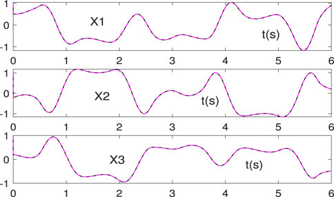
Here, we set all the parameters m, p, q, z, k1, k2, k3, k4 in the non-linear activation function (14) to 5, and the state solutions generated by the proposed NAZNN model are shown in Figure 1.
According to Figure 1, it can be observed that the black curves quickly coincide with the red curves, which indicate that the state solutions generated by the NAZNN model converge to the theoretical solutions of Eq. 1 in a very brief period of time.
In addition, the residual errors of the NAZNN model (12) and the IZNN model activated by LAF, PSAF, HSAF and SBPAF for solving the above same equation are compared in Figure 2. Figure 2A shows only the residual error of the NAZNN model (12) converges rapidly to 0, while the IZNN model activated by the activation functions converges slowly.
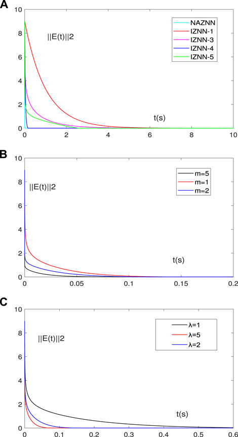
FIGURE 2. Comparative experiments of the ZNN models for solving Eq. 1. (A) is the residual errors of all the models, (B) is the residual errors of the NAZNN model with different parameter m, (C) is the residual errors of the NAZNN model with different parameter λ.
Furthermore, it can be observed that the convergence speed becomes faster as the value of m increases in Figure 2B. This phenomenon indicates that the time required for the NAZNN model (12) to solve inequality (1) becomes shorter as m increases. Finally, from Figure 2C, we can see that the convergence time of the NAZNN model becomes smaller as the convergence coefficient λ increases, which indicates that the convergence speed of the NAZNN model is also closely related to its convergence coefficient. Therefore, we can set these parameter values according to the accuracy requirements.
It is worth mentioning that the system environment in reality is complex and variable. Therefore, the NAZNN model (13) is used to solve inequality (1) with the different noises to highlight its robustness, and the simulation result are shown in Figure 3.
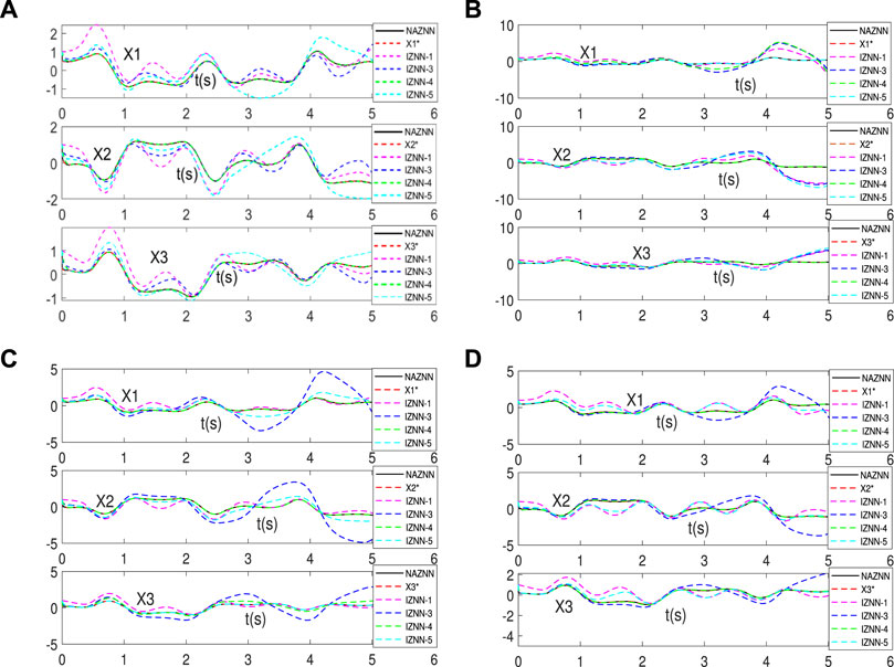
FIGURE 3. Neural state solution of NAZNN model and IZNN model for solving Eq.1 with different noises, (A) is add Y(t)=0.5, (B) is add Y(t)=0.5t, (C) is add Y(t)=cost, (D) is add exponential interference.
As can be seen from Figure 3A-D, even under various noise conditions, all the black curves still coincide exactly with the red dashed curves, while the other curves do not coincide quickly and accurately with the red dashed line. This indicates that only the transient solution of the NAZNN model quickly tracks the theoretical solution of inequality (1), while the transient solutions of other models cannot. Therefore, it can be concluded that the NAZNN model solves the time-varying linear Equation 1 perfectly in a predetermined time, and it has better convergence and greater robustness than the existing ZNN models. To further compare the errors of the NAZNN model (13) with the IZNN model for solving the inequality system (1) under different noise conditions, the residual errors of all the model are shown in Figure 4.
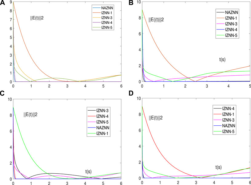
FIGURE 4. Residual errors of the NAZNN model and the IZNN models for solving Eq. 1 when disturbed by various noises. The noises considered in (A-D) are the same ones with (A-D).
As can be seen in Figure 4A-D, the residual errors of the NAZNN model (13) drops to 0 in a very short time in the presence of four noises. However, the residual errors of the IZNN model fluctuate greatly or converge very slowly, or even fail to converge to 0 due to noises.
4 Applications on wheeled robots
In this section, the NAZNN model is applied to solve the wheeled robot trajectory tracking problems [50,54].
4.1 The construction of NAZNN model for wheeled robot trajectory tracking with physical constrains
4.1.1 Modeling of the physical constrained manipulator
In this subsection, the modeling of a movable six-joint three-wheel manipulator is introduced and its 3D model is shown in Figure 5A.
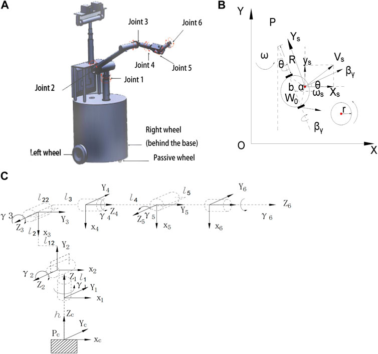
FIGURE 5. Wheeled robot modeling process. (A) is 3D model, (B) is the model of mobile platform, (C) is Wheeled robot world coordinate system and axis coordinate system.
The equations of motion are analyzed according to the wheeled robot mobile device in Figure 5B, and the parameters are shown below.
W0: the midpoint of the drive axis, expressed in the world coordinate system as (x0, y0, z0).
Ws: the position of the manipulator, expressed in the world coordinate system (xs, ys, zs).
d: distance from W0 to Ws, d = 0.1m.
b: distance from the midpoint of the drive axis to the left and right drive wheels, b = 0.32m.
r: radius of each driving wheel, r = 0.1025m.
θ: The heading angle of the mobile device, expressed as the angle of the mobile device from the X-axis to the symmetry axis; its time derivative is the heading speed.
P: the mobile device rotates around the point P.
R: the distance of point P from the left driving wheel.
ω: the rotation speed of the mobile device around point P; and
The next step is to establish robot model of the mobile device. Assume that each link of the wheeled robot is rigid and there is no relative sliding between the mobile device and the robot arm. Based on Figure 5B, the kinematic equations for the mobile device are established as follows, and the detailed derivation can be found in Supplementary Appendix S1A.
Rewrite Eq. 36 into matrix form
where
where
where δz ∈ Rn indicates the position relative to the world coordinate system, and
According to the above analysis, the coordinates of the end-effector in the world coordinate system can be expressed as (xz, yz, zz), and the kinematic relations of the end-effector can be obtained as follows:
where δs is a three-dimensional vector, and the detailed expressions and calculation procedure for δs are shown in Supplementary Appendix S1B. Besides, Eq. 40 can be obtained by the time derivative of the speed level equation.
It can be reformulated as:
where
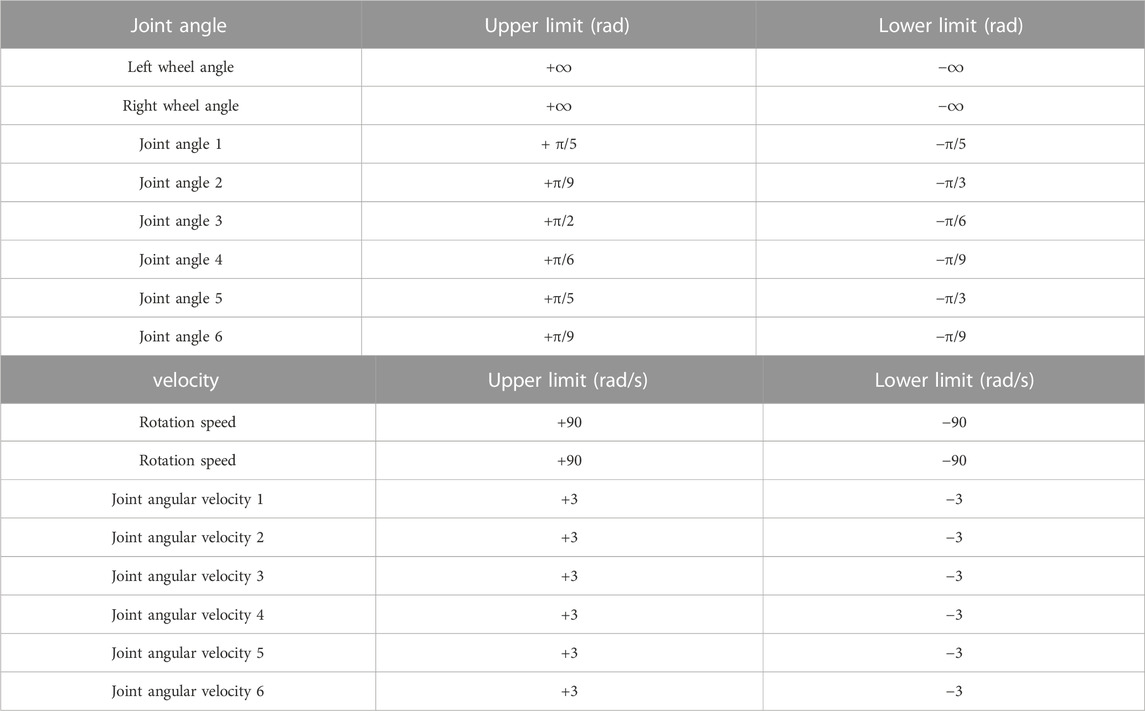
Conventional control approaches have difficulty in handling trajectory tracking with constraints, and physical constraints are rarely considered before. However, almost all controllers have physical constraints (angular constraints, speed constraints, etc.). Therefore, it is very realistic and necessary to consider the failure problem of trajectory tracking of wheeled robots subject to constraints. The physical constraints of wheeled robot trajectory tracking considered in this work are listed below.
where v > 0 is the feedback gain,
To deal with the problem at the joint velocities level, the range of active wheel rotation angles of the wheeled robot and the range of robot joint angles are transformed into the corresponding velocities as follows.
where the coefficient η > 0 is used to calculate the range of joint velocities, and the coefficient has η special points. The value of η may lead to a sudden deceleration of the joint velocity when the wheeled robot approaches the joint limit, in numerical terms,
In summary, the velocity control of wheeled robot trajectory tracking with physical constraints can be formulated as
where q ∈ Rm denotes the combined velocity vector
4.1.2 NAZNN model for trajectory tracking control of wheeled robots
Equation 46 with the above conditions can be transformed as
Convert (47) to matrix form by referring to the CTVLMA calculation process.
D1(t), E1(t), y(t) and o(t) are process quantities generated by the calculation process with reference to CTVLMA. Let
Then, define
The NAZNN model for trajectory tracking control of wheeled robots with physical constraints is obtained.
4.2 Simulation results on physically constrained wheeled robots
In this section, the above NAZNN model (50) and other related ZNN models are all used to solve the same wheeled robotic arm trajectory tracking problem with physical constraints for the purpose of comparison.
The initial heading angle of the wheeled robot is set to zero, and the motion direction of the wheeled robot is parallel to the x-axis of the world coordinate system, and its initial position is (xs(0), ys(0), zs(0)) = (0, 0, 0). The initial state of the robot arm joint is [π/5; π/3; π/6; π/3; π/6; π/3]T, and the rotation angle of the drive wheel set to β1 = βr = 0rad. In summary, the initial value of the combined angular vector is ϕ (0) = [0,0; π/5; π/3; π/6; π/3; π/6; π/3]T.
4.2.1 NAZNN model simulation results
In this subsection, the proposed NAZNN model is applied to control the wheeled robot to perform trajectory tracking, and the corresponding simulation results are represented in Figure 6. As observed in Figure 6, the wheeled robot controlled by the NAZNN model completes the tracking task effectively.
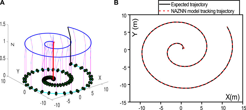
FIGURE 6. NAZNN model-controlled wheeled robot trajectory and the end-effector trajectory. (A) is Robot operation trajectory, (B) is Robotic arm end-effector trajectory.
Additionally, the joint angle variation of the robot for spiral trajectory tracking is represented in Figure 7, and the joint velocity of the robot for the tracking process is represented in Figure 8.
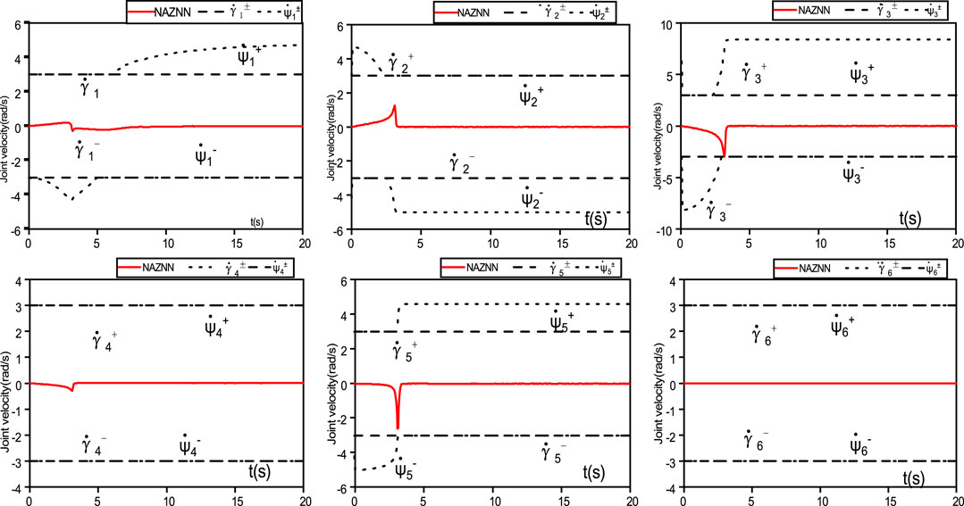
FIGURE 8. The NAZNN model-controlled wheeled robot successfully finishes the trajectory tracking with 6 joint velocities change.
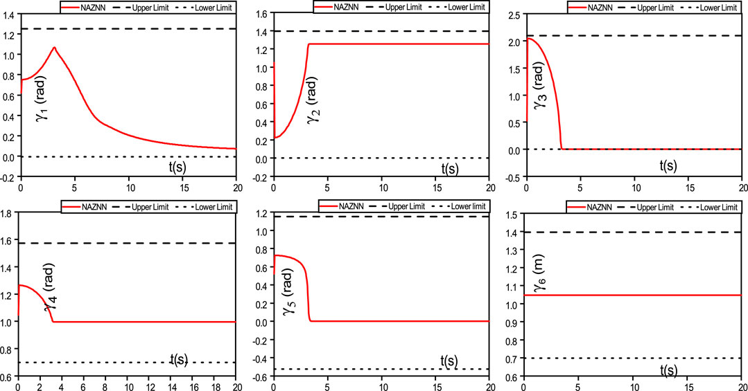
It can be observed in Figures 7, 8 that the joint angles and joint speeds of the NAZNN model-controlled wheeled robotic arm are within the physical limits until the end of the trajectory tracking, which indicates that the NAZNN model-controlled wheeled robotic arm successfully completes the tracking task.
4.2.2 IZNN models simulation results
In this subsection, the IZNN models controlled robots are also used for the same tracking task for the purpose of comparison, and the corresponding simulation results are represented in Figures 9–12.
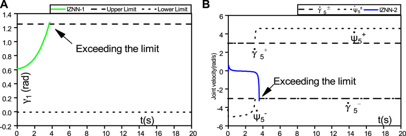
Figure 9 shows the difference between the IZNN-1 and IZNN-2 models. Both the IZNN-1 and IZNN-2 models are activated by the linear activation function. Because the parameter size has a great impact on the models, the actual experimental results are also different.
As observed in Figure 9, the IZNN-1 model controlled robot fails the tracking task due to robot joint angle
The wheeled robot controlled by the IZNN-3 model for the same tracking task is presented in Figures 10–12. As observed in Figure 10, the wheeled robot controlled by the IZNN-3 model also fails the tracking task. Additionally, the joint angle variation of the robot controlled by the IZNN-3 model for spiral trajectory tracking is represented in Figure 11, and the joint velocity of the robot controlled by the IZNN-3 model for the tracking process is represented in Figure 12.
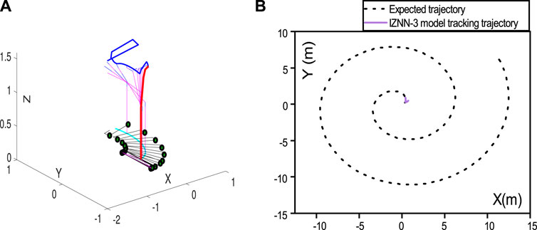
FIGURE 10. (A) represent IZNN-3 model-controlled wheeled robot's joint trajectory, (B) represent the end-effector trajectory.
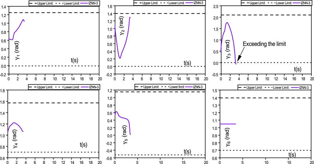
FIGURE 11. The IZNN-3 model-controlled wheeled robot fails trajectory tracking with joint angles exceed limits.
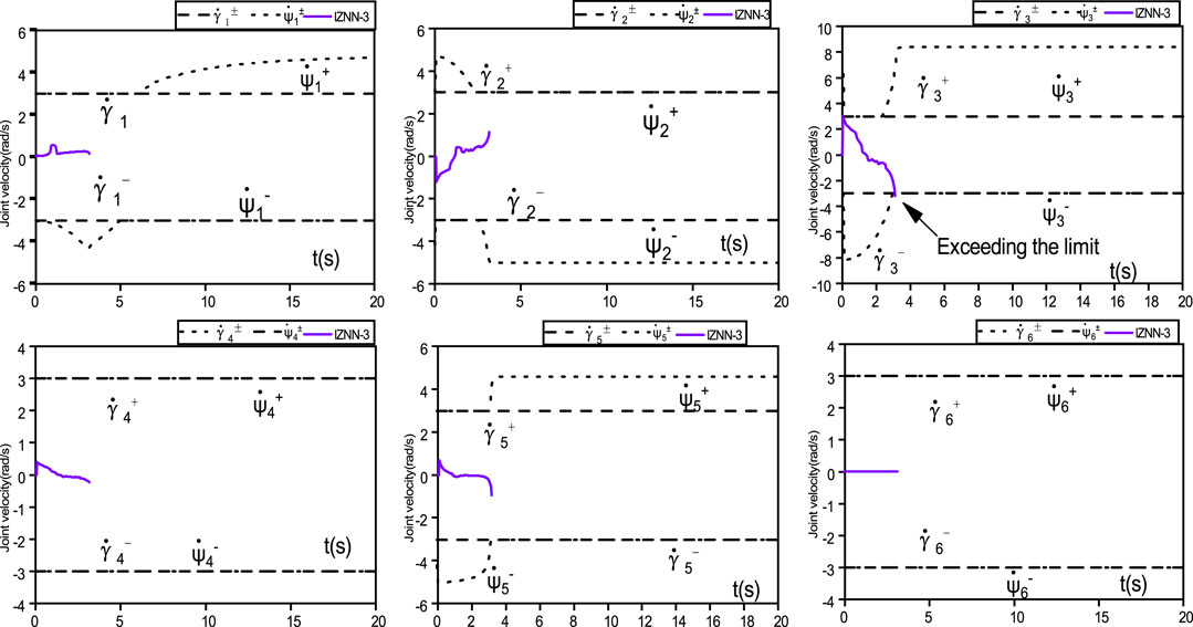
FIGURE 12. The IZNN-3 model-controlled wheeled robot fails trajectory tracking with Joint velocities exceed limits.
As observed in Figure 10, Figures 11, 12, the tracking task is interrupted, with the joint speed
In summary, the proposed NAZNN model has better control performances compared to other models for physically constrained wheeled robot trajectory tracking, and it completes the physically constrained trajectory tracking task smoothly and accurately without exceeding the joint angle and joint speed. The detailed comparative results of the models are presented in Table 3.
5 Conclusion
In this paper, a NAZNN model is proposed and effective applied to solve CTVLME problems. It is theoretically demonstrated that the NAZNN model can obtain the exact solutions of CTVLME problems. The validity and superiority of the NAZNN model is further verified by two numerical examples. Besides, the proposed NAZNN model is also applied to the failure problem of trajectory tracking of wheeled robots with physical constraints. Finally, the NAZNN model is used to control the wheeled robot to complete trajectory tracking under restricted conditions to prove the feasibility of this control method.
Data availability statement
The original contributions presented in the study are included in the article/Supplementary Material, further inquiries can be directed to the corresponding authors.
Author contributions
All authors listed have made a substantial, direct, and intellectual contribution to the work and approved it for publication.
Funding
This work was supported by the National Natural Science Foundation of China (62273141), Natural Science Foundation of Hunan Province (2020JJ4315), Scientific Research Fund of Hunan Provincial Education Department (20B216).
Conflict of interest
The authors declare that the research was conducted in the absence of any commercial or financial relationships that could be construed as a potential conflict of interest.
Publisher’s note
All claims expressed in this article are solely those of the authors and do not necessarily represent those of their affiliated organizations, or those of the publisher, the editors and the reviewers. Any product that may be evaluated in this article, or claim that may be made by its manufacturer, is not guaranteed or endorsed by the publisher.
Supplementary material
The Supplementary Material for this article can be found online at: https://www.frontiersin.org/articles/10.3389/fphy.2023.1159212/full#supplementary-material
References
1. Katsikis VN, Mourtas SD, Stanimirović PS, Zhang Y. Solving complex-valued time-varying linear matrix equations via qr decomposition with applications to robotic motion tracking and on angle-of-arrival localization. IEEE Trans Neural Networks Learn Syst (2021) 33(8):3415–24. doi:10.1109/tnnls.2021.3052896
2. Kayastha S, Katupitiya J, Pearce G, Rao A. Comparative study of post-impact motion control of a flexible arm space robot. Eur J Control (2022) 69:100738. doi:10.1016/j.ejcon.2022.100738
3. Yang S, Zhang Y, Wen H, Jin D. Coordinated control of dual-arm robot on space structure for capturing space targets. Adv Space Res (2023) 71(5):2437–48. doi:10.1016/j.asr.2022.10.027
4. Park FC, Kim B, Jang C, Hong J. Geometric algorithms for robot dynamics: A tutorial review. Appl Mech Rev (2018) 70. doi:10.1115/1.4039078
5. Yang B, Yang W. Modular approach to kinematic reliability analysis of industrial robots. Reliab Eng Syst Saf (2023) 229:108841. doi:10.1016/j.ress.2022.108841
6. Gyebrószki G, Csernák G, Milton JG, Insperger T. The effects of sensory quantization and control torque saturation on human balance control. Chaos: Interdiscip J Nonlinear Sci (2021) 31:033145. doi:10.1063/5.0028197
7. Khan AT, Li S, Li Z. Obstacle avoidance and model-free tracking control for home automation using bio-inspired approach. Adv Control Appl Eng Ind Syst (2022) 4(1):e63. doi:10.1002/adc2.63
8. Li ZF, Li JT, Li XF, Yang YJ, Xiao J, Xu BW. Intelligent tracking obstacle avoidance wheel robot based on arduino. Proced Comput Sci (2020) 166:274–8. doi:10.1016/j.procs.2020.02.100
9. Liu D, Wang J, Lei T, Wang S. Active suspension control with consensus strategy for dynamic posture tracking of wheel-legged robotic systems on uneven surfaces. ISA Trans (2022) 131:628–38. doi:10.1016/j.isatra.2022.05.021
10. Carlucho I, De Paula M, Acosta GG. An adaptive deep reinforcement learning approach for mimo pid control of mobile robots. ISA Trans (2020) 102:280–94. doi:10.1016/j.isatra.2020.02.017
11. Singhal K, Kumar V, Rana K. Robust trajectory tracking control of non-holonomic wheeled mobile robots using an adaptive fractional order parallel fuzzy pid controller. J Franklin Inst (2022) 359(9):4160–215. doi:10.1016/j.jfranklin.2022.03.043
12. Li Y, Li Y-X, Tong S. Event-based finite-time control for nonlinear multi-agent systems with asymptotic tracking. IEEE Trans Autom Control (2022) 1–8. doi:10.1109/tac.2022.3197562
13. Rosas-Vilchis A, de Loza AF, Aguilar LT, Cieslak J, Henry D, Montiel-Ross O. Trajectory tracking control for an autonomo vehicle using a decoupling approach. In: 2020 28th Mediterranean Conference on Control and Automation (MED). IEEE (2020). p. 375–80.
14. Lu Q, Chen J, Wang Q, Zhang D, Sun M, Su C-Y. Practical fixed-time trajectory tracking control of constrained wheeled mobile robots with kinematic disturbances. ISA Trans (2022) 129:273–86. doi:10.1016/j.isatra.2021.12.039
15. Yu F, Shen H, Liu L, Zhang Z, Huang Y, He B, et al. Ccii and fpga realization: A multistable modified fourth-order autonomous chua’s chaotic system with coexisting multiple attractors. Complexity (2020) 2020:1–17. doi:10.1155/2020/5212601
16. Pan Y, Wu Y, Lam H-K. Security-based fuzzy control for nonlinear networked control systems with dos attacks via a resilient event-triggered scheme. IEEE Trans Fuzzy Syst (2022) 30(10):4359–68. doi:10.1109/tfuzz.2022.3148875
17. Dai J, Chen Y, Xiao L, Jia L, He Y. Design and analysis of a hybrid gnn-znn model with a fuzzy adaptive factor for matrix inversion. IEEE Trans Ind Inform (2021) 18(4):2434–42. doi:10.1109/tii.2021.3093115
18. Katsikis VN, Stanimirović PS, Mourtas SD, Xiao L, Karabašević D, Stanujkić D. Zeroing neural network with fuzzy parameter for computing pseudoinverse of arbitrary matrix. IEEE Trans Fuzzy Syst (2021) 30(9):3426–35. doi:10.1109/tfuzz.2021.3115969
19. Kong Y, Chen S, Jiang Y, Wang H, Chen H. Zeroing neural network with fuzzy parameter for cooperative manner of multiple redundant manipulators. Expert Syst Appl (2023) 212:118735. doi:10.1016/j.eswa.2022.118735
20. Gong J, Jin J. A better robustness and fast convergence zeroing neural network for solving dynamic nonlinear equations. Neural Comput Appl (2021) 35:77–87. doi:10.1007/s00521-020-05617-9
21. Xiao L, Liu S, Wang X, He Y, Jia L, Xu Y. Zeroing neural networks for dynamic quaternion-valued matrix inversion. IEEE Trans Ind Inform (2021) 18(3):1562–71. doi:10.1109/tii.2021.3090063
22. Yu F, Yu Q, Chen H, Kong X, Mokbel AAM, Cai S, et al. Dynamic analysis and audio encryption application in iot of a multi-scroll fractional-order memristive hopfield neural network. Fractal and Fractional (2022) 6(7):370. doi:10.3390/fractalfract6070370
23. Barajas CA, Gobbert M, Polf JC. (2021). Deep residual fully connected neural network classification of compton camera based prompt gamma imaging for proton radiotherapy. UMBC Student Collection.
24. Jin J, Zhao L, Chen L, Chen W. A robust zeroing neural network and its applications to dynamic complex matrix equation solving and robotic manipulator trajectory tracking. Front Neurorobotics (2022) 16:1065256. doi:10.3389/fnbot.2022.1065256
25. Jin J, Zhu J, Zhao L, Chen L. A fixed-time convergent and noise-tolerant zeroing neural network for online solution of time-varying matrix inversion. Appl Soft Comput (2022) 130:109691. doi:10.1016/j.asoc.2022.109691
26. He B, Dai C, Lang J, Bing P, Tian G, Wang B, et al. A machine learning framework to trace tumor tissue-of-origin of 13 types of cancer based on dna somatic mutation. Biochim Biophys Acta (BBA)-Molecular Basis Dis (2020) 1866(11):165916. doi:10.1016/j.bbadis.2020.165916
27. He B, Zhang Y, Zhou Z, Wang B, Liang Y, Lang J, et al. A neural network framework for predicting the tissue-of-origin of 15 common cancer types based on rna-seq data. Front Bioeng Biotechnol (2020) 8:737. doi:10.3389/fbioe.2020.00737
28. Jin J, Gong J. A noise-tolerant fast convergence znn for dynamic matrix inversion. Int J Comput Math (2021) 98(11):2202–19. doi:10.1080/00207160.2021.1881498
29. Jin J, Xiao L, Lu M, Li J. Design and analysis of two ftrnn models with application to time-varying sylvester equation. IEEE Access (2019) 7:58945–50. doi:10.1109/access.2019.2911130
30. Ma M, Xiong K, Li Z, Sun Y. Dynamic behavior analysis and synchronization of memristor-coupled heterogeneous discrete neural networks. Mathematics (2023) 11(2):375. doi:10.3390/math11020375
31. Jin J, Chen W, Chen C, Chen L, Tang Z, Chen L, et al. A predefined fixed-time convergence znn and its applications to time-varying quadratic programming solving and dual-arm manipulator cooperative trajectory tracking. IEEE Trans Ind Inform (2022) 1–12. doi:10.1109/tii.2022.3220873
32. Jin J, Chen W, Zhao L, Chen L, Tang Z. A nonlinear zeroing neural network and its applications on time-varying linear matrix equations solving, electronic circuit currents computing and robotic manipulator trajectory tracking. Comput Appl Math (2022) 41(7):319. doi:10.1007/s40314-022-02031-w
33. Jin J, Qiu L. A robust fast convergence zeroing neural network and its applications to dynamic sylvester equation solving and robot trajectory tracking. J Franklin Inst (2022) 359(7):3183–209. doi:10.1016/j.jfranklin.2022.02.022
34. Ma M, Lu Y, Li Z, Sun Y, Wang C. Multistability and phase synchronization of rulkov neurons coupled with a locally active discrete memristor. Fractal Fractional (2023) 7(1):82. doi:10.3390/fractalfract7010082
35. Jin J, Chen W, Qiu L, Zhu J, Liu H. A noise tolerant parameter-variable zeroing neural network and its applications. Math Comput Simul (2023) 207:482–98. doi:10.1016/j.matcom.2023.01.012
36. Jin J, Zhu J, Zhao L, Chen L, Chen L, Gong J. A robust predefined-time convergence zeroing neural network for dynamic matrix inversion. IEEE Trans Cybernetics (2022) 1–14. doi:10.1109/tcyb.2022.3179312
37. Jin J, Gong J. An interference-tolerant fast convergence zeroing neural network for dynamic matrix inversion and its application to mobile manipulator path tracking. Alexandria Eng J (2021) 60(1):659–69. doi:10.1016/j.aej.2020.09.059
38. Hu Z, Xiao L, Dai J, Xu Y, Zuo Q, Liu C. A unified predefined-time convergent and robust znn model for constrained quadratic programming. IEEE Trans Ind Inform (2020) 17(3):1998–2010. doi:10.1109/tii.2020.2996215
39. Luo J, Yang H, Yuan L, Chen H, Wang X. Hyperbolic tangent variant-parameter robust znn schemes for solving time-varying control equations and tracking of mobile robot. Neurocomputing (2022) 510:218–32. doi:10.1016/j.neucom.2022.08.066
40. Yang Y, Zhang Y. Superior robustness of power-sum activation functions in zhang neural networks for time-varying quadratic programs perturbed with large implementation errors. Neural Comput Appl (2013) 22(1):175–85. doi:10.1007/s00521-011-0692-5
41. Li S, Chen S, Liu B. Accelerating a recurrent neural network to finite-time convergence for solving time-varying sylvester equation by using a sign-bi-power activation function. Neural Process Lett (2013) 37(2):189–205. doi:10.1007/s11063-012-9241-1
42. Xiao L. Accelerating a recurrent neural network to finite-time convergence using a new design formula and its application to time-varying matrix square root. J Franklin Inst (2017) 354(13):5667–77. doi:10.1016/j.jfranklin.2017.06.012
43. Zhu J, Jin J, Chen W, Gong J. A combined power activation function based convergent factor-variable znn model for solving dynamic matrix inversion. Math Comput Simul (2022) 197:291–307. doi:10.1016/j.matcom.2022.02.019
44. Xiao L, He Y, Liao B. A parameter-changing zeroing neural network for solving linear equations with superior fixed-time convergence. Expert Syst Appl (2022) 208:118086. doi:10.1016/j.eswa.2022.118086
45. Li J, Zhu X, Shi Y, Wang J, Guo H. Real-time robot manipulator tracking control as multilayered time-varying problem. Appl Math Model (2021) 96:355–66. doi:10.1016/j.apm.2021.03.021
46. He W, Xue C, Yu X, Li Z, Yang C. Admittance-based controller design for physical human–robot interaction in the constrained task space. IEEE Trans Autom Sci Eng (2020) 17(4):1937–49. doi:10.1109/tase.2020.2983225
47. Dou R, Yu S, Li W, Chen P, Xia P, Zhai F, et al. Inverse kinematics for a 7-dof humanoid robotic arm with joint limit and end pose coupling. Mech Machine Theor (2022) 169:104637. doi:10.1016/j.mechmachtheory.2021.104637
48. Aouiti C, Miaadi F. A new fixed-time stabilization approach for neural networks with time-varying delays. Neural Comput Appl (2020) 32(8):3295–309. doi:10.1007/s00521-019-04586-y
49. Tutsoy O, Polat A. Linear and non-linear dynamics of the epidemics: System identification based parametric prediction models for the pandemic outbreaks. ISA Trans (2022) 124:90–102. doi:10.1016/j.isatra.2021.08.008
50. Xing H, Torabi A, Ding L, Gao H, Li W, Tavakoli M. Enhancing kinematic accuracy of redundant wheeled mobile manipulators via adaptive motion planning. Mechatronics (2021) 79:102639. doi:10.1016/j.mechatronics.2021.102639
51. Wang D, Wei W, Wang X, Gao Y, Li Y, Yu Q, et al. Formation control of multiple mecanum-wheeled mobile robots with physical constraints and uncertainties. Appl Intell (2022) 52:2510–29. doi:10.1007/s10489-021-02459-3
52. Ding L, Xiao L, Zhou K, Lan Y, Zhang Y. A New RNN Model With a Modified Nonlinear Activation Function Applied to Complex–Valued Linear Equations. IEEE. Access (2018) 6:62954–62962. doi:10.1109/ACCESS.2018.2876665
53. Li W, Xiao L, Liao B. A Finite-time convergent and noise-rejection recurrent neural network and its discretization for dynamic nonlinear equations solving. IEEE. Transactions on Cybernetics (2020) 50(7):3195–3207. doi:10.1109/TCYB.2019.2906263
Keywords: zeroing neural network, activation function, robot trajectory tracking, trajectory tracking fault problem, ABB simulation
Citation: Lan X, Jin J and Liu H (2023) Towards non-linearly activated ZNN model for constrained manipulator trajectory tracking. Front. Phys. 11:1159212. doi: 10.3389/fphy.2023.1159212
Received: 05 February 2023; Accepted: 17 February 2023;
Published: 13 March 2023.
Edited by:
Hairong Lin, Hunan University, ChinaReviewed by:
Yujiao Dong, Hangzhou Dianzi University, ChinaSen Zhang, Nanjing Normal University, China
Copyright © 2023 Lan, Jin and Liu. This is an open-access article distributed under the terms of the Creative Commons Attribution License (CC BY). The use, distribution or reproduction in other forums is permitted, provided the original author(s) and the copyright owner(s) are credited and that the original publication in this journal is cited, in accordance with accepted academic practice. No use, distribution or reproduction is permitted which does not comply with these terms.
*Correspondence: Xiangyu Lan, MTI5OTQ2NDU2MEBxcS5jb20=; Jie Jin, amo2NzEyM0BobnVzdC5lZHUuY24=
 Xiangyu Lan1*
 Jie Jin
