- Key Laboratory of Particle Acceleration Physics and Technology, Institute of High Energy Physics, Chinese Academy of Sciences (CAS), University of Chinese Academy of Sciences, Beijing, China
Preserving the beam quality of a high-brightness electron beam is a noteworthy issue when delivering the electron bunch through a beam transfer line. In a beam transfer line with a large deflection angle, e.g., a 180-deg transport arc comprised of a large amount of dipoles, emission of coherent synchrotron radiation (CSR) can lead to transverse emittance dilution. In addition, the longitudinal dispersion may cause undesirable bunch length variation. Both effects can degrade beam quality. Nevertheless, design and optimization of a 180-deg transport arc that can be well applied to practical applications is a challenging problem, considering the practical nonlinear effects of a real lattice and the contributions of transient CSR at the dipole edges and CSR in the subsequent drifts. In this study, we present the design and optimization of a compact 180-deg transport arc comprised of multi-triple-bend achromat (TBA) cells, aiming at suppressing the CSR-induced emittance growth and avoiding bunch length variation simultaneously. The TBA cells and optics along the arc are adjusted to suppress the CSR-induced emittance growth and bunch length variation cell by cell, after which a multi-objective optimization of the arc is conducted. Practical considerations including lattice nonlinear effects and a full one-dimensional CSR model (including transient CSR and CSR in drifts) are taken into account.
Introduction
Since the development of the high-gain theory of free-electron lasers (FELs) and the advent of high-gain infrared (IR) and ultraviolet (UV) FELs [1–4], the production of high average FEL power has received considerable critical attention. As an industrial application, the need to apply high-power FELs to extreme ultraviolet (EUV) lithography [5] has obviously made energy recovery linac (ERL)-based FELs an appealing choice. ERLs are inherently continuous wave (CW) devices and are able to serve multiple FELs. In FEL spreaders or ERL turnaround arcs, preserving the beam quality can be a critical issue when delivering a high-brightness beam with typically picosecond (ps) or sub-ps bunch length, high peak current up to a few kilo-amperes (kA), and micrometer (μm) or sub-μm normalized horizontal emittance [6, 7]. However, in such an arc comprised of multiple dipoles, the emission of coherent synchrotron radiation (CSR) can degrade the beam quality by causing emittance dilution [8–12], thus decreasing beam brightness, which may limit FEL output power [13]. Longitudinally, CSR can also give rise to microbunching instability (MBI) [14–19]. In addition, the longitudinal dynamics can be affected by longitudinal dispersion functions via the correlation of the longitudinal bunch coordinate z and momentum deviation δ of a particle [20–23], resulting in undesirable bunch length variation. In the high-brightness beam transport line/arc design, suppression of the CSR-induced emittance growth is highly desirable, while preserving the bunch length simultaneously to maintain high beam quality.
To control the impact of CSR on beam emittance, approaches such as the beam envelope matching method [10] and optical balance method [11] have been proposed, which are based on single or multiple double-bend achromats (DBAs). For the sake of making an isochronous cell, a triple-bend achromat (TBA) cell might be a promising candidate, as the first-order longitudinal dispersion function R56 can be easily canceled [22, 23]. As for suppressing CSR in a TBA cell, it has been reported that [22] a kind of TBA design could yield both first-order isochronicity, i.e., R56 = 0, and minimized steady-state CSR (denoted as ss-CSR hereafter)-induced emittance growth. Moreover, the study in Ref. [23] has demonstrated that in a TBA cell with periodic optics, the CSR-induced emittance growth and the longitudinal dispersion up to high orders can be minimized simultaneously when the horizontal transfer matrix entries between the first two dipoles in the TBA follow [m11, m21 (m−1)] ≈ (−2, 0).
As for preserving the bunch emittance in an arc comprised of multiple cells, the related studies mainly focus on two aspects of applications: one is arc compressors that are used to compress the bunch length and bend the beam simultaneously [6, 13, 25–27]; the other is isochronous transport arcs that are not expected to involve with bunch compression. In isochronous transport arc designs, the beam envelope matching method is commonly used to numerically minimize the emittance growth [10, 28]. Nevertheless, the design and optimization of an arc suitable for transporting a high-brightness beam is worthy of further studies, considering practical issues like the nonlinear effects of a real lattice and full 1D CSR effects in addition to ss-CSR, i.e., including transient CSR (denoted as tr-CSR) and CSR in the subsequent drifts (denoted as dr-CSR) [29, 30]. Practically, the transfer line/arc optics can be related to not only the first-order transfer map but also the high-order terms, which can produce nonlinear effects, e.g., chromatic and geometric aberrations [21, 31–33]. As the horizontal coordinate x and longitudinal coordinate z can be correlated with δ via some of the high-order terms, e.g., T166, T266, and T566, such nonlinear effects may also give rise to emittance growth and bunch length variation. Preservation of bunch emittance and bunch length with such practical issues taken into account can be a challenging problem, especially for an arc comprised of multiple cells, which may require numerical methods to effectively obtain optimized design schemes.
In this study, we demonstrate the feasibility of designing a multi-TBA cell-based compact quasi-isochronous 180-deg arc suitable for transporting high-brightness beams with minimized CSR-induced emittance growth by applying the theoretical work in Ref. [23] to multiple cells.
In the following sections, first, the arc design is described. Then, the numerical scans and optimization processes and the corresponding simulation results are presented. By comparing some representative optimization results, the possible correlation between CSR-induced emittance growth and MBI gain is discussed. The design strategy and the numerical scans and optimization processes may be helpful as a starting point for practically optimized transport arc designs.
Arc design
In this section, we describe the design goal of the transport arc and introduce the design of the TBA unit cell that forms the arc.
The design goal of the transport arc is to maintain the beam quality while achieving a large bending angle of 180 deg within a compact footprint, i.e., the survey length is about 40 m. To maintain the beam quality of a high-brightness beam, the arc is expected to be (quasi)-isochronous to avoid undesirable bunch length variation and CSR-immune for emittance preservation. A TBA cell is used as the basic unit cell of the transport arc, and we consider a center-symmetric design with three identical dipoles. With the goal of designing a compact 180-deg arc, dipole parameters and the length of the TBA single cell are carefully analyzed. Through a great deal of tests, the parameters of the dipole magnets are settled, i.e., the dipole lengths are LB = 0.4 m and the bending angles are θ = 4°. Thus, it requires a total of 15 cells to form an arc. The length of a single cell is about 4.2 m to accommodate the survey requirement. The total arc length is about 63 m.
The TBA unit cell is designed according to the theoretical CSR-cancellation condition in a quasi-isochronous TBA [23], which is derived with only ss-CSR and linear transfer map of the lattice being considered. The dipole parameters are set at the aforementioned values. Between the dipoles, four families of quadrupoles are used to match the achromatic condition while adjusting m11, m21, and Twiss functions simultaneously. Specifically, in this design, the values of m11 and m21 are set to be −1.998 and −0.012, respectively, where we have used the accurate values of these two matrix elements derived using the accurate first-order transfer matrix of a sector dipole [24].
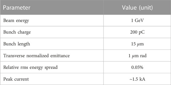
For the single cell, horizontal Twiss parameters at the TBA entrance, i.e., initial αx0 and βx0 are scanned in search of an optimal matching beam envelope for the orientation of a nonzero net CSR kick for a practical TBA, as mentioned in Ref. [10]. Although the theoretical condition in Ref. [23] reports a TBA with periodic optics, we further scan to find the optimal Twiss parameters for better CSR minimization in a practical cell instead of directly adopting the periodic optics solution. The TBA cell is tested using ELEGANT [34], employing the initial bunch parameters of a high-brightness beam listed in Table 1. For the case with ss-CSR and the first-order transfer map being considered, the relative normalized horizontal emittance growth Δɛn/ɛn is as low as 0.67% for a single TBA cell with periodic Twiss parameters of αx0 = 0 and βx0 = 4.96 m, whereas it is found that Δɛn/ɛn can be further suppressed to 0.61% for a single TBA cell with the initial Twiss parameters of αx0 = 0.3 and βx0 = 1.3 m, which are deviated from the periodic Twiss parameters. The TBA unit cell design is also tested with a transfer map up to the third order, with tr-CSR and dr-CSR included. The simulation results show that Δɛn/ɛn is suppressed to 1.52% with the aforementioned periodic Twiss parameters. And Δɛn/ɛn can be further suppressed to 1.38% with the initial Twiss parameters of αx0 = 0.4 and βx0 = 1 m, which are also deviated from the periodic Twiss parameters and are different from the optimal Twiss parameters with ss-CSR and the first-order transfer map being considered.
Although the differences in Δɛn/ɛn seem tiny and the TBA single cell design is physically CSR-immune using all the abovementioned sets of Twiss parameters, the results somewhat indicate the dependence of the CSR-induced emittance growth on the lattice optic, as mentioned in Refs [10, 12, 26]. Moreover, the results indicate that Δɛn/ɛn is generally larger when the lattice nonlinear effects and tr-CSR and dr-CSR are included.
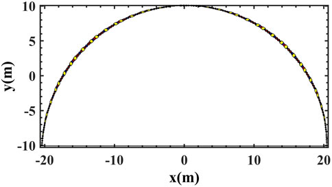
An arc design is obtained based on the TBA unit cell. The resulting schematic of the arc is shown in Figure 1. Considering the optics dependence of CSR-induced emittance suppression, in the following, we consider a practical single-pass transfer arc with non-periodic optics. To flexibly control the arc optics, for the in-between sections of the unit cells, two quadrupoles are used from cell-1∼3 and three quadrupoles are used from cell-3∼15. Moreover, two families of sextupoles are inserted between the dipoles in cell-2∼15 the dipoles, which will not influence the linear lattice optics but will affect the high-order terms of the transfer map (e.g., T166, T266, and T566) [31]. Such an arc will be adjusted and optimized in the following section with the full 1D CSR model and lattice nonlinear effects taken into account.
Optimization and results
For the sake of practical consideration, in this section, adjustments based on numerical scans and optimization of the TBA-based transport arc are performed considering full 1D CSR and the lattice transfer map up to the third order. Cell-by-cell adjustments based on numerical scans are first conducted and then multi-objective particle swarm optimization (MOPSO) of the adjusted arc design is performed.
First, the design setting of each TBA cell, i.e., m11,i and m21,i (where i represents the ith cell), and the corresponding optimal Twiss parameters are scanned based on the ELEGANT simulation results using the parameters listed in Table 1. In this step, the impact of lattice nonlinear effects together with tr-CSR and dr-CSR on linear optics settings is considered in the scans, while the high-order terms of the transfer map are not specially controlled. Only the quadrupoles and drifts are adjusted to change m11 and m21. The sextupole strengths are coarsely tuned. Considering the impact of the aforementioned lattice nonlinear effects and tr-CSR and dr-CSR, the optimal design settings of the TBA cells might deviate from the theoretical result of a single unit cell. Moreover, the optimal Twiss parameters for each cell can be different considering that the bunch phase space distributions might have been changed under the influence of CSR and lattice nonlinear effects. Thus, the adjustments are conducted cell by cell. Specifically, we vary the settings of m11 and m21 for a certain cell in the vicinity of the theoretical result. For a specific setting of m11 and m21, the optimal Twiss parameters are also scanned in search of the minimal Δɛn/ɛn value and relative bunch length variation |Δσz/σz| (both values are obtained with ELEGANT simulations) that can be achieved for this setting of the cell.
In search of optimal m11,i and m21,i for each TBA cell, we scan the setting of m11 and m21 in the vicinity of the theoretical setting (denoted as
After the numerical scan of cell-1, the real bunch distribution can be obtained with ELEGANT. To proceed, using this distribution, the numerical scan of cell-2 is conducted. Similar processes are performed for the 15 cells. After such scans, an arc design is obtained (denoted as Solution-Scan hereafter). The ELEGANT simulation results of this design show that the final emittance at the arc exit is approximately 7.64 μm rad and the final bunch length is approximately 12.96 μm, i.e., Δɛn/ɛn and |Δσz/σz| are approximately 6.64% and 13.6%, respectively. The scanning results show that the optimal m11,i for each cell is exactly the theoretical value
It is found that the emittance growth of Solution-Scan is still large with a relatively large bunch length variation. This may result from the contributions of the lattice nonlinear effects, which can also give rise to emittance growth and bunch length variation [21, 31–33]. Moreover, CSR-induced energy spread can be distribution-dependent [28], which indicates that it might be very hard to suppress the emittance growth in the last few cells of the arc where the bunch distributions are distorted under the influence of CSR and lattice nonlinear effects. For example, Δɛn/ɛn of each cell is controlled below 1% for cell-1∼5 and below 10% for cell-5∼8. However, in the last seven cells, Δɛn/ɛn for each cell is generally close to 30%. So it seems that to obtain a minimum emittance growth of an arc comprised of multiple cells, it might be better to optimize the arc design as a whole compared to scanning and adjusting the arc cell by cell.
Second, to explore the possibility of finding an arc design scheme with minimized CSR-induced emittance growth, we adopted the widely used MOPSO [35] method to perform a global optimization of the arc. The MOPSO method is suitable for handling multi-objective optimization problems in the accelerator design (see, e.g., [36–39]). It provides a way to optimize a problem by iteratively improving the candidate solutions according to a criterion of the solution quality quantized as the “fitness value,” which is also referred to as the “objective function”. Each candidate is referred to as a particle that possesses a position in the n-dimensional space defined by n variables. Each particle moves randomly but is influenced by “pbest” and “gbest”. “Pbest” represents the best fitness value the individual has hitherto achieved, and “gbest” represents the best fitness value that the whole group has experienced. The solutions are ranked in accordance with their fitness values. By adjusting the variables to a certain bounded range, the candidate solutions are updated iteratively while searching for optima [40–42].
For the optimization variables, considering the basic need for isochronicity and CSR-induced emittance suppression, the m11,i and m21,i are fixed to the scanned optimal values and only the in-between sections of the 15 cells are optimized. Specifically, the strengths of quadrupoles and lengths of drifts of the in-between sections are considered to be variables. The lengths of all quadrupoles are fixed to be 0.15 m. Apart from these, the strengths of the sextupoles inside the TBA cells are set to be variables with the lengths being fixed to 0.1 m. In addition, the initial Twiss parameters at the arc entrance, i.e., αx0, βx0 and αy0, βy0 are set to be variables. Totally, there are 126 variables, including 40 quadrupoles strengths, 28 sextupoles strengths, 54 drift lengths and four Twiss parameters. The corresponding setting is regarded as a seed in the optimization. All the 126 variables are adjusted within the preset ranges, e.g., the drift lengths range from 0.01 to 0.5 m, the strengths of quadrupoles vary within ±60 m−2, and the strengths of the sextupoles vary within ±3 × 10³ m−3. The initial Twiss parameters vary in the range of [−50, 50] for αx,y0 and [0.1 m, 100 m] for βx,y0.
The two objective functions are set to be the absolute values of the following: the weighted relative CSR-induced emittance growth Δɛn/ɛn and the weighted relative bunch length variation Δσz/σz obtained with ELEGANT using the initial bunch parameters listed in Table 1. By imposing constraints, the optimization is conducted with practical considerations. For example, the transverse βx,y functions along the arc are controlled to a reasonable range of 0.1–1,000 m, and the survey length of the arc is constrained to be approximately 40 m. If any of the constraints is violated during the optimization, the objective functions are multiplied by a factor larger than 1, which is referred to as the “weight factor.” These weight factors are used to measure the degree that a specific variable setting accommodates for the optimization constraints [36–39].
By adding fluctuations to Solution-Scan, 600 initial seeds are generated and optimized. After evolving over 200 generations, the optimization results have become convergent, especially for those solutions with small relative emittance growths, e.g., Δɛn/ɛn < 2.4. The last 70 generations are presented in Figure 2.
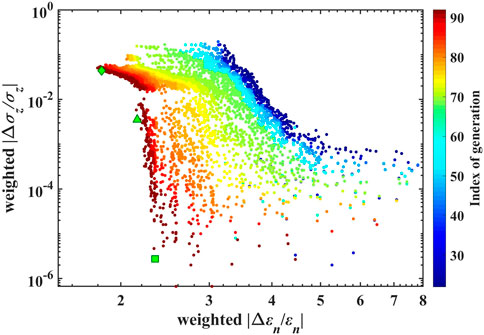
FIGURE 2. Convergence trend of the objective functions (weighted |Δɛn/ɛn| and weighted |Δσz/σz| obtained with ELEGANT using the initial beam parameters of a high-brightness beam listed in Table 1) in the optimization of a 180-deg transport arc with tr-CSR, dr-CSR, and the lattice transfer map up to the third order being considered. Only the last 70 generations are shown in this figure. The solutions are marked using a green diamond, a triangle, and a square corresponding to Solution-OPT-I∼III.
The figure shows that in the selected variable ranges, |Δσz/σz| can be optimized to the order of 10–6, while it seems that |Δɛn/ɛn| can only be minimized to approximately 1.8. As an illustration, three representative frontier solutions in the optimization are selected and compared in detail. The related comparisons and discussions are presented in the following section.
Comparison of the optimized ARC designs
In this section, we further look into the corresponding arc designs of several representative frontier solutions of the MOPSO with full 1D CSR and high-order terms of the lattice transfer map being considered. To clearly show the advancement of the optimized arc designs, the specific horizontal and longitudinal dispersion functions and parameters of the quadrupoles and sextupoles of the selected representative designs in MOPSO are compared with the design Solution-Scan. Then, MBI gains of the designs are compared, while the contribution of tr-CSR and dr-CSR is also discussed.
Three frontier solutions in the MOPSO results are selected (marked in Figure 2): one has a relatively small Δɛn/ɛn value which is approximately 1.8 (marked using a green diamond, denoted by Solution-OPT-I), one has a relatively small |Δσz/σz| value (marked using a green square, denoted by Solution-OPT-III), and one is located between the two previous solutions (marked using a green triangle, denoted by Solution-OPT-II). In the following section, the corresponding arc designs of the three solutions are carefully compared with Solution-Scan.
Comparison of the horizontal and longitudinal dispersion functions
The related horizontal and longitudinal dispersion functions of Solution-Scan and Solution-OPT-I∼III are listed in Table 2. The R56 values of these designs are all same, i.e., 2.923 × 10⁻³ m. Thus, they are not specifically listed in the table.
The optimized arc designs of Solution-OPT-I∼III generally yield smaller Δɛn/ɛn and |Δσz/σz| values than those of Solution-Scan, which may be the result of the mitigation of the high-order dispersion effects. Table 2 shows that compared with Solution-Scan, the optimized arc designs of Solution-OPT-I∼III yield relatively small second-order horizontal and longitudinal dispersion functions, i.e., T166, T266, and T566. As mentioned previously, the aberrations caused by leaking of transverse dispersion can lead to emittance growth [21, 31–33]. Furthermore, high-order longitudinal dispersions can result in bunch length variation [21, 23].
Then, we focus on Solution I∼III. Table 2 indicates that the emittance growth of a certain design is related to second-order horizontal dispersion functions, while the bunch length variation is related to high-order longitudinal dispersion functions. For Solution-OPT-I with the smallest Δɛn/ɛn value among the three solutions, T166 and T266 are lower than the other two solutions, especially for T266, which is two orders of magnitude lower. For Solution-OPT-II and -III with smaller |Δσz/σz| values, T566 and U5666 values are smaller than those of Solution-OPT-I.
In Figure 3, the ELEGANT simulation results of optics functions, bunch lengths, and the normalized horizontal emittance along the corresponding arc of Solution-OPT-I are presented as an example.

FIGURE 3. Simulation results of the related parameters along the corresponding arc of Solution-OPT-I considering full 1D CSR model and the lattice transfer map up to the third order: (A) optics functions; (B) bunch length; (C) normalized horizontal emittance. The results are obtained with ELEGANT using the high-brightness beam parameters listed in Table 1.
Comparison of lattice element parameters
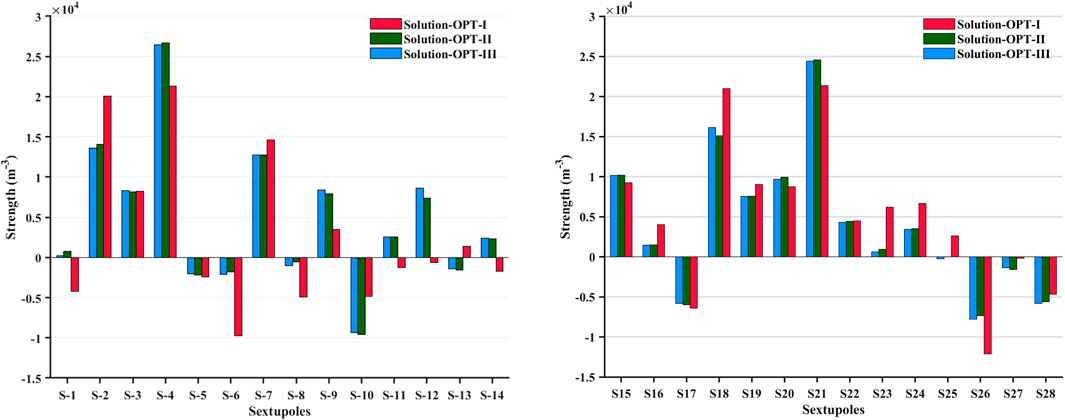
For Solution-Scan and Solution-OPT-I∼III, we compare the strengths of 40 quadrupoles in the in-between sections and the strengths of 28 sextupoles in the TBA cells. For Solution-Scan, the sextupoles are not specially adjusted; thus, they are not included in the comparison. The results are shown in Figures 4, 5, respectively.
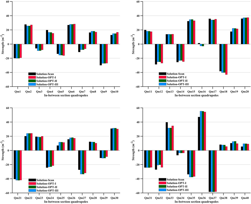
FIGURE 4. Comparison of the strengths of 40 quadrupoles in the in-between section of Solution-Scan and Solution-OPT-I ∼III.
It appears that the strengths of 40 quadrupoles are not notably different except for Qm-16 (in the section between cell-5 and cell-6) and Qm-33 (in the section between cell-11 and cell-12), which indicates that first-order transfer maps of the four solutions are close to each other. However, it seems that the strengths of 28 sextupoles of Solution-OPT-I∼III are different. Specifically, the sextupole strengths in Solution-OPT-I are remarkably different from those in Solution-OPT-II and -III. Some of the sextupoles in Solution-OPT-I even have opposite signs compared with those in Solution-OPT-II and -III, which are as follows: S-1 (in cell-2), S-11 and S-12 (in cell-7), S-13 and S-14 (in cell-8), and S-25 (in cell-14) (six of 28 sextupoles). This means that some of the focusing sextupoles change to defocusing sextupoles (or vice versa) in Solution-OPT-I compared with Solution-OPT-II and -III, which may result in differences between horizontal and longitudinal dispersion functions, as listed in Table 2.
Comparison of the MBI gains
The MBI gains of Solution-Scan and Solution-OPT-I∼III are compared using the semi-analytical tool Volterra [17, 19], and the results are shown in Figure 6. The results indicate that the CSR-induced emittance growth at the exit of the arc might be correlated with the MBI gain. This can be understood through the CSR suppression condition proposed in Ref. [23], which is based on the assumption of the Gaussian bunch distribution. If the bunch distribution is no longer Gaussian, such a condition may not correspond to the minimized CSR-induced emittance growth and even lose efficacy. This suggests that the MBI gain might serve as an indicator that shows the degree of longitudinal phase space distortion [18, 19].
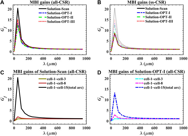
FIGURE 6. MBI gains of Solution-Scan and Solution-OPT-I ∼III under different conditions (A) all-CSR considered; (B) only ss-CSR considered (the results with all-CSR considered are shown together, but light colored); (C) The MBI gains of cell-1∼cell-3, cell-3∼cell-8 and the total arc of Solution-Scan with all-CSR considered; (D) The MBI gains of cell-1∼cell-3, cell-3∼cell-8 and the total arc of Solution-OPT-I with all-CSR considered.
As can be seen from Figure 6A, compared with Solution-Scan, CSR-induced MBI gains are suppressed for Solution-OPT-I∼III, which indicates the mitigation of the MBI effects. Moreover, Figure 6C and Figure 6D show that the MBI effect becomes more significant as the bunch passes through more cells, which indicates that the longitudinal phase space distribution is distorted more significantly. Thus, in the last few cells in the arc, it might be more difficult to preserve the emittance for such a distorted bunch.
We further look into the MBI gains of the designs with only ss-CSR included. It is found that tr-CSR and dr-CSR significantly contribute to MBI gain for a certain arc design, as mentioned in Ref. [18]. As can be seen from Figure 6B, MBI gains for Solution-Scan and Solution-OPT-I∼III are very close to each other with only ss-CSR being considered [which are overlapped in Figure 6B], and they are notably lower than the case with tr-CSR and dr-CSR being included.
Initial bunch parameter sensitivity tests
To identify the range of parameters that allows feasibility of such an arc for transporting a high-brightness beam, in this section, the sensitivity tests on the initial bunch parameters are conducted for the corresponding arc designs of Solution-OPT-I as an example. The initial bunch parameters vary in the ranges close to the parameters listed in Table 1. The test results show that the emittance growth of this design is not sensitive to the initial uncorrelated energy spread or energy chirp. Nevertheless, the emittance growth is closely related to the initial bunch length, bunch charge, and initial bunch emittance.
The results of univariate tests on the relevant input beam parameters (i.e., initial bunch length σzi, bunch charge Q, initial horizontal emittance ɛnxi, initial uncorrelated energy spread σδi, and energy chirp hi) are shown in Figure 7.
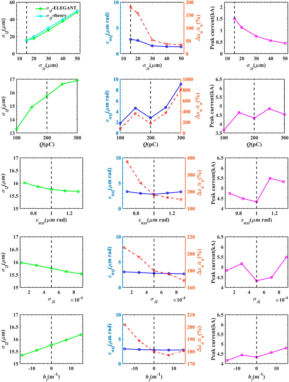
FIGURE 7. Results of the sensitivity tests of the dependence of σzf, ɛnxf, and Δɛn/ɛn and the peak current on the initial bunch parameters of the corresponding arc of Solution-OPT-I.
As can be seen from the figures, σzf and ɛnxf are not sensitive to σδi or hi, with the largest difference of Δɛn/ɛn being below 40% when varying σδi in the range of [0, 1 × 10⁻³] and hi in the range of [-15 m−1, 15 m−1]. It is noted that insensitivity to hi is important, as a compressed bunch typically has an energy chirp. If isochronicity is not satisfactorily guaranteed, the bunch length of a chirped bunch will have a significant variation, which might couple with the CSR effect and result in severe bunch quality degradation [6, 23].
Nevertheless, it appears that the emittance growth of this design changes significantly with the varying σzi, Q, and ɛnxi values. Specifically, the Δɛn/ɛn value becomes larger when the σzi value is smaller, Q value is larger, and ɛnxi value is smaller. The reason is that the CSR-induced rms energy spread σCSR has scale relationships with σzi and Q as
Conclusion and discussion
In this study, based on the theoretical CSR-cancellation condition of a quasi-isochronous TBA cell proposed in Ref. [23], the design and optimization of a TBA-based 180-deg transport arc is presented. The optimal design setting of m11,i and m21,i for each cell is first scanned, and the optics along the arc are adjusted. The scanning results indicate that the optimal m11,i values are close to the theoretical value in Ref. [23], while m21,i values show relatively large deviations when a full 1D CSR model and a high-order lattice transfer map are considered. The optimal Twiss parameters of each cell are different and deviated from the periodic optics functions.
Then, the arc is optimized by adopting the MOPSO method, aiming at suppressing the CSR-induced emittance growth and avoiding bunch length variation simultaneously. The optimization results show that in the selected variable ranges, for a high-brightness beam with parameters of 1 GeV, 200 pC, 15 μm, and 1 μm rad, the final emittance can be controlled to approximately 2.8 μm rad (Δɛn/ɛn ∼ 1.8) and |Δσz/σz| can be suppressed to about 5%. Moreover, it has been tested that the obtained arc design is not sensitive to the initial uncorrelated energy spread or energy chirp, which is suitable for transporting a high-brightness beam that typically has an energy chirp. In addition, such a TBA-based 180-deg transport arc can serve as a turnaround arc in ERL-based facilities. It has been tested that for a typical initial beam with parameters of 100 pC, 600 μm, and 0.5 μm rad, the Δɛn/ɛn value is below 1% and the bunch length remains almost unchanged. In addition, the obtained arc has a compact footprint, with the survey length being approximately 40 m.
It is found that in our tests, the CSR-induced emittance growth and MBI gain are correlated to some extent. Particularly, for the last few cells in the arc, an exploded MBI gain often indicates a severely distorted longitudinal phase space distribution of the bunch [18, 19]. The theoretical CSR-cancellation condition may not work well or even lose efficacy for such a distorted bunch, and hence, the arc design may yield an imperfectly canceled or even uncontrollable emittance growth. This gives us a hint that simply pursuing CSR-induced emittance growth suppression might not be an effective way to obtain optimal design schemes. Instead, emittance growth and MBI gain suppression should be considered comprehensively. For example, MBI gain can be adopted as a weight factor in the MOPSO of the CSR-induced emittance growth.
The design strategy and numerical scans and optimization processes presented in this paper may hopefully serve as a starting point for designing a compact transport arc. Future research could continue to explore the possibility of further global optimization, with the CSR-induced emittance growth and MBI gain suppression being considered comprehensively.
Also, it is noted that the suppression conditions of the CSR-induced emittance growth and MBI effects can be different, i.e., a certain design with suppressed MBI gain does not definitely ensure a suppressed CSR-induced emittance growth and vice versa [18]. It can be a rather complex problem to take both issues into account. And such problem may only be optimized through numerical optimizations. First, high-order longitudinal dispersion functions can make a contribution to the MBI gain [18, 19]. Apart from R56, z can be correlated with δ through high-order longitudinal dispersion functions, which can also distort the bunch longitudinal phase space distribution [18, 21, 23]. Moreover, the MBI suppression condition can be related to the Twiss parameters (see, e.g., Ref. [18]). This means that the requirements of suppressing the CSR-induced emittance growth and MBI gain might conflict with each other. In addition, as illustrated previously, tr-CSR and dr-CSR can have a significant impact on the MBI gain [18].
Apart from this, optimized design schemes can be further explored to mitigate the lattice nonlinear effects. For example, multi-poles can be adopted in cells (e.g., sextupoles [21] and octupoles [43]). Moreover, further global optimizations based on the parameter ranges of actual hardware and start-to-end simulations are worthy of being studied further. Following similar designs and numerical scans and optimization processes as presented in this paper, it would be feasible to achieve optimized practical arc design schemes.
Data availability statement
The raw data supporting the conclusion of this article will be made available by the authors, without undue reservation.
Author contributions
CZ: conceptualization, methodology, visualization, software, investigation, data curation, formal analysis, and writing—original draft. YJ: validation, resources, writing—review and editing, and supervision. All authors contributed to the article and approved the submitted version.
Funding
This work was supported by the National Natural Science Foundation of China (Nos 11922512 and 12275284) and the Youth Innovation Promotion Association of Chinese Academy of Sciences (No. Y201904).
Conflict of interest
The authors declare that the research was conducted in the absence of any commercial or financial relationships that could be construed as a potential conflict of interest.
Publisher’s note
All claims expressed in this article are solely those of the authors and do not necessarily represent those of their affiliated organizations, or those of the publisher, the editors, and the reviewers. Any product that may be evaluated in this article, or claim that may be made by its manufacturer, is not guaranteed or endorsed by the publisher.
References
1. Pellegrini C. The history of X-ray free-electron lasers. EPJ H (2021) 37:659–708. doi:10.1140/epjh/e2012-20064-5
2. Ackermann W, Asova G, Ayvazyan V, Azima A, Baboi N, Bähr J, et al. Operation of a free-electron laser from the extreme ultraviolet to the water window. Nat Photon (2007) 1:336–42. doi:10.1038/nphoton.2007.76
3. Emma P, Akre R, Arthur J, Bionta R, Bostedt C, Bozek J, et al. First lasing and operation of an ångstrom-wavelength free-electron laser. Nat Photon (2010) 4:641–7. doi:10.1038/nphoton.2010.176
4. Ishikawa T, Aoyagi H, Asaka T, Asano Y, Azumi N, Bizen T, et al. A compact x-ray free-electron laser emitting in the sub-Ångstr’́om region. Nat Photon (2012) 6:540–4. doi:10.1038/nphoton.2012.141
5. Schneidmiller E, Vogel V, Weise H, Yurkov M. Potential of the FLASH free electron laser technology for the construction of a kW-scale light source for next-generation lithography. J Micro-nanolithography Mems Moems (2012) 11:021122–1. doi:10.1117/1.JMM.11.2.021122
6. Akkermans JAG, Di Mitri S, Douglas D, Setija ID. Compact compressive arc and beam switchyard for energy recovery linac-driven ultraviolet free electron lasers. Phys Rev Accel Beams (2017) 20(8):080705. doi:10.1103/PhysRevAccelBeams.20.080705
7. Di Mitri S, Spampinati S. Microbunching instability study in a linac-driven free electron laser spreader beam line. Phys Rev Accel Beams (2017) 20(12):120701. doi:10.1103/PhysRevAccelBeams.20.120701
8. Derbenev YS, Rossbach J, Saldin EL, Shiltsev VD. Microbunch radiative tail-head interaction, DESY, Hamburg, Germany. Rep. TESLA-FEL 95-05 (1995). doi:10.3204/PUBDB-2018-04128
9. Hajima R. A first-order matrix approach to the analysis of electron beam emittance growth caused by coherent synchrotron radiation. Jpn J Appl Phys (2003) 42:L974–6. doi:10.1143/JJAP.42.L974
10. Hajima R. Emittance compensation in a return arc of an energy-recovery linac. Nucl Instrum Methods Phys Res Sect A (2004) 528(1–2):335–9. doi:10.1016/j.nima.2004.04.063
11. Di Mitri S, Cornacchia M, Spampinati S. Cancellation of coherent synchrotron radiation kicks with optics balance. Phys Rev Lett (2013) 110:014801. doi:10.1103/PhysRevLett.110.014801
12. Jiao Y, Cui X, Huang X, Xu G. Generic conditions for suppressing the coherent synchrotron radiation induced emittance growth in a two-dipole achromat. Phys Rev ST Accel Beams (2014) 17:060701. doi:10.1103/PhysRevSTAB.17.060701
13. Di Mitri S, Cornacchia M. Transverse emittance-preserving arc compressor for high-brightness electron beam-based light sources and colliders. Europhys Lett (2015) 109:62002. doi:10.1209/0295-5075/109/62002
14. Heifets S, Stupakov G, “Beam instability and microbunching due to coherent synchrotron radiation”, in Proc.19th IEEE particle accelerator conference (PAC 2001), Chicago, Illinois, 18–22. 2001, paper TPPH081, pp.1856-1858.
15. Huang Z, Kim K-J. Formulas for coherent synchrotron radiation microbunching in a bunch compressor chicane. Phys Rev Accel Beams (2002) 5:074401. doi:10.1103/PhysRevSTAB.5.074401
16. Venturini M. Microbunching instability in single-pass systems using a direct two-dimensional Vlasov solver. Phys Rev Accel Beams (2007) 10:104401. doi:10.1103/PhysRevSTAB.10.104401
17. Tsai C-Y, Douglas D, Li R, Tennant C. Linear microbunching analysis for recirculation machines. Phys Rev Accel Beams (2016) 19:114401. doi:10.1103/PhysRevAccelBeams.19.114401
18. Tsai C-Y, Di Mitri S, Douglas D, Li R, Tennant C. Conditions for coherent-synchrotron-radiation-induced microbunching suppression in multibend beam transport or recirculation arcs. Phys Rev Accel Beams (2017) 20:024401. doi:10.1103/PhysRevAccelBeams.20.024401
19. Tsai C-Y, Derbenev YS, Douglas D, Li R, Tennant C. Vlasov analysis of microbunching instability for magnetized beams. Phys Rev Accel Beams (2017) 20:054401. doi:10.1103/PhysRevAccelBeams.20.054401
20. England RJ, Rosenzweig JB, Andonian G, Musumeci P, Travish G, Yoder R. Sextupole correction of the longitudinal transport of relativistic beams in dispersionless translating sections. Phys Rev ST Accel Beams (2005) 8:012801. doi:10.1103/PhysRevSTAB.8.012801
21. Charles TK, Paganin DM, Latina A, Boland MJ, Dowd RT. Current-horn suppression for reduced coherent-synchrotron-radiation-induced emittance growth in strong bunch compression. Phys Rev Accel Beams (2017) 20(3):030705. doi:10.1103/PhysRevAccelBeams.20.030705
22. Venturini M. Design of a triple-bend isochronous achromat with minimum coherent-synchrotron-radiation-induced emittance growth. Phys Rev Accel Beams (2016) 19(6):064401. doi:10.1103/PhysRevAccelBeams.19.064401
23. Zhang C, Jiao Y, Tsai C-Y. Quasi-isochronous triple-bend achromat with periodic stable optics and negligible coherent-synchrotron-radiation effects. Phys Rev Accel Beams (2021) 24:060701. doi:10.1103/PhysRevAccelBeams.24.060701
24. Zhang C, Jiao Y, Tsai C-Y, “Theoretical analysis of the conditions for an isochronous and CSR-immune triple-bend achromat with stable optics”, in Proceedings of the 12th international particle accelerator conference (IPAC 2022), Campinas, SP, Brazil (JACOW, Geneva, Switzerland, 2022), pp. 786–9.
25. Douglas DR, Benson SV, Li R, Roblin Y, Tennant CD, Krafft GA, et al. “Control of synchrotron radiation effects during recirculation with bunch compression”, in Proceedings of the 6th international particle accelerator conference (IPAC 20215, Richmond, VA, USA (JACOW, Geneva, Switzerland, 2015), pp. 1910–2.
26. Di Mitri S. Feasibility study of a periodic arc compressor in the presence of coherent synchrotron radiation. Nucl Instrum Methods Phys Res Sect A (2016) 806:184–92. doi:10.1016/j.nima.2015.10.015
27. Zhang C, Jiao Y, Liu W, Tsai C-Y. Suppression of the coherent synchrotron radiation induced emittance growth in a double-bend achromat with bunch compression. Phys Rev Accel Beams (2023). (Accepted).
28. Shimada M, Yokoya K, Suwada T, Enomoto A. Lattice and beam optics design for suppression of CSR-induced emittance growth at the KEK-ERL test facility. Nucl Instrum Methods Phys Res Sect A (2007) 575:315–20. doi:10.1016/j.nima.2007.02.095
29. Stupakov G, Emma P. CSR wake for a short magnet in ultra-relativistic limit” Proceedings of the EPAC (2002). p. 1479–81. doi:10.2172/799089
30. Khan DZ, Raubenheimer TO. Approximated expressions for the coherent synchrotron radiation effect in various accelerator scenarios. Phys Rev Accel Beams (2021) 24(8):080701. doi:10.1103/PhysRevAccelBeams.24.080701
31. Björklund Svensson J, Charles TK, Lundh O, Thorin S. Third-order double-achromat bunch compressors for broadband beams. Phys Rev Accel Beams (2019) 22(10):104401. doi:10.1103/PhysRevAccelBeams.22.104401
32. Sun Y. Second-order achromat design based on FODO cell. Phys Rev ST Accel Beams (2011) 14(6):060703. doi:10.1103/PhysRevSTAB.14.060703
33. Lindstrøm CA, Adli E. Design of general apochromatic drift-quadrupole beam lines. Phys Rev Accel Beams (2016) 19(7):071002. doi:10.1103/PhysRevAccelBeams.19.071002
34. Borland M. Simple method for particle tracking with coherent synchrotron radiation. Phys Rev ST Accel Beams (2001) 4(7):070701. doi:10.1103/PhysRevSTAB.4.070701
35. Coello Coello CA, Lechuga MS. Mopso: A proposal for multiple objective particle swarm optimization. In: Proc. 2002 congress on evolutionary computation (CEC’02). Honolulu, HI, USA (2002). p. 1051–6. doi:10.1109/CEC.2002.1004388
36. Pang X, Rybarcyk LJ. Multi-objective particle swarm and genetic algorithm for the optimization of the LANSCE linac operation. Nucl Instrum Methods Phys Res Sect A (2014) 741:124–9. doi:10.1016/j.nima.2013.12.042
37. Huang X, Safranek J. Nonlinear dynamics optimization with particle swarm and genetic algorithms for SPEAR3 emittance upgrade. Nucl Instrum Methods Phys Res Sect A (2014) 757:48–53. doi:10.1016/j.nima.2014.04.078
38. Jiao Y, Xu G. Optimizing the lattice design of a diffraction-limited storage ring with a rational combination of particle swarm and genetic algorithms. Chin Phys C (2017) 41(2):027001. doi:10.1088/1674-1137/41/2/027001
39. Xu J, Yang P, Liu G, Bai Z, Li W. Constraint handling in constrained optimization of a storage ring multi-bend-achromat lattice. Nucl Instrum Methods Phys Res Sect A (2020) 988:164890. doi:10.1016/j.nima.2020.164890
40. Akbari R, Ziarati K. A rank based particle swarm optimization algorithm with dynamic adaptation. J Comput Appl Math (2011) 235(8):2694–714. doi:10.1016/j.cam.2010.11.021
41. Li J, Feikes J, Goslawski P, Ries M, “Particle swarm optimization algorithm applied in online commissioning at the MLS and BESSY II”, in Proceedings of the 8th international particle accelerator conference (IPAC 2017), Copenhagen, Denmark (JACOW, Geneva, Switzerland, 2017), pp. 3700–3.
42. Tharwat A, Schenck W. A conceptual and practical comparison of PSO-style optimization algorithms. Expert Syst Appl (2021) 167:114430. doi:10.1016/j.eswa.2020.114430
Keywords: CSR, emittance growth compensation, bunch length, triple-bend achromat, transport arc, MOPSO optimization
Citation: Zhang C and Jiao Y (2023) Design and optimization of a compact quasi-isochronous 180-deg transport arc with suppressed CSR-induced emittance growth. Front. Phys. 11:1154735. doi: 10.3389/fphy.2023.1154735
Received: 31 January 2023; Accepted: 17 April 2023;
Published: 03 May 2023.
Edited by:
Bo Liu, Chinese Academy of Sciences, ChinaReviewed by:
Helmut Burkhardt, European Organization for Nuclear Research (CERN), SwitzerlandSimone Di Mitri, Elettra Sincrotrone Trieste, Italy
Si Chen, Chinese Academy of Sciences, China
Copyright © 2023 Zhang and Jiao. This is an open-access article distributed under the terms of the Creative Commons Attribution License (CC BY). The use, distribution or reproduction in other forums is permitted, provided the original author(s) and the copyright owner(s) are credited and that the original publication in this journal is cited, in accordance with accepted academic practice. No use, distribution or reproduction is permitted which does not comply with these terms.
*Correspondence: Yi Jiao, amlhb3lpQGloZXAuYWMuY24=
 Chengyi Zhang
 Yi Jiao