- 1China Spallation Neutron Source, Institute of High Energy Physics, Chinese Academy of Sciences, Dongguan, Guangdong, China
- 2Institute of High Energy Physics, Chinese Academy of Sciences, Beijing, China
- 3School of Nuclear Science and Technology, University of Chinese Academy of Sciences, Beijing, China
Superconducting undulators (SCUs) have the advantages of generating stronger magnetic field and the radiation hardness compared to permanent magnet undulators. Therefore, SCUs are valuable to be applied in the free-electron lasers (FELs) driven by high-repetition-rate linear accelerators. The Insertion Device Group at the Institute of High Energy Physics (IHEP) in China started an R&D project to produce NbTi planar SCU prototypes with 15 mm period length. Several SCU prototypes, including short mock-ups, a 0.5-m-long SCU, and a 1.5-m-long SCU, have been successfully produced and cryogenic tested. The short mock-up coils were cooled by a liquid helium free cryostat to be quench trained at 4 K. The maximum current in the coils reached 500 A and the magnetic peak field exceed 1 T with 7 mm gap. The 0.5-m-long SCU was tested by using a vertical test system. The correction coils were confirmed with the ability in both correcting the magnetic field integrals and the phase error. The 1.5-m-long SCU was not only vertically tested, but also installed in a cryostat to be operated with high current over a long time. We applied the gap adjustment method to reduce the phase error within 9 degrees. The development of SCUs at the IHEP is introduced in this paper in detail.
1 Introduction
The next-generation self-amplified spontaneous emission (SASE) free-electron lasers (FELs) operating in the continuous-wave (CW) mode with a MHz-level repetition rate have become a focus of research. Such FEL facilities will increase the average brightness and offer more flexible time patterns of the beam. Undulators are key devices in accelerator-based FELs that can provide several orders of magnitude higher flux rates than bending magnets. Undulators consist of periodic arrays of permanent magnets or superconducting coils. Electrons are forced to undergo oscillations when traveling through the periodic magnet structure and thus to radiate photon beams concentrated in narrow energy bands. The quality of the radiation directly depends on the performance of the undulator.
Currently, permanent magnet undulators (PMUs) are mainly used in accelerators. In order to increase the magnetic field strength of PMUs at a short period length, researchers developed the in-vacuum undulator (IVU) by installing the permanent magnet arrays and supporting structure in a large vacuum chamber. In this case, the vacuum chamber in the undulator gap is removed and the gap distance can be compressed down to about 5 mm. Based on IVUs, the cryogenic permanent magnet undulator (CPMU) has been developed by cooling the permanent magnet with liquid nitrogen to increase the remanence of the magnetic material. However, the permanent magnet could be demagnetized by the radiation when the beam loss happens at the undulator section during the accelerator operation. For IVUs and CPMUs, the damage could be more serious because there is no vacuum chamber in the gap. Although CPMUs use the magnetic materials with large coercive force at low temperature to reduce the demagnetization effect, the radiation damage risk cannot be ignored. Radiation damage may be even worse for the CW-FEL facilities due to the high beam current. In addition, the magnetic field strength of PMUs reaches an upper limit due to limitations in the available magnetic materials. Superconducting undulators have better radiation hardness with no risk of material remanence and can provide stronger magnetic fields than PMUs [1–4]. In this case, it is important to develop SCUs for valuable applications in CW-FELs.
SCUs have been developed in many institutes worldwide and are successfully operated at two light sources: the KIT synchrotron and APS [5–8]. The Institute of High Energy Physics (IHEP) in China started an R&D project to develop NbTi planar undulators in 2020. In this paper, we introduced the progress of the NbTi SCU project at the IHEP, including the development of three different SCU prototypes. The SCU structure was determined using the simulation program OPERA-3D [9]. The effect of the correction coil on the magnetic field and the field deviation caused by the pole and coil errors were also analyzed. Several short mock-up coils with 4.5 periods were produced at the beginning of the project to test the manufacturing techniques and to obtain quench training experience. A liquid helium-free cryostat was specially designed to test the short SCU prototype under 4.2 K [10]. The load current in the mock-up coils successfully reached up to 500 A, and the corresponding magnetic peak field exceeded 1 T. Then, a 0.5-m-long SCU prototype was manufactured and fabricated. A vertical test system was set up to test the SCU prototypes in a Dewar submerged in liquid helium [11]. The vertical test system contained magnetic field measurement equipment to obtain the field distribution of the SCU on the axis. During the test, the current in the main coils of the SCU reached 480 A, giving a corresponding magnetic field of over 1 T after several quenches. The ability of the correction coils to optimize the first and second field integrals was also verified. In addition, the phase error of the magnetic field can be also corrected with a suitable correction current. The final target of our R&D project was to develop a 1.5-m-long SCU. Recently, the 1.5-m-long SCU prototype was produced and tested vertically in a Dewar. After the vertical test, the cryogenic test was conducted by installing this 1.5-m-long SCU in a large cryostat horizontally, and thus 1.5-m-long SCU was proved to be successful under low temperatures.
2 SCU simulation
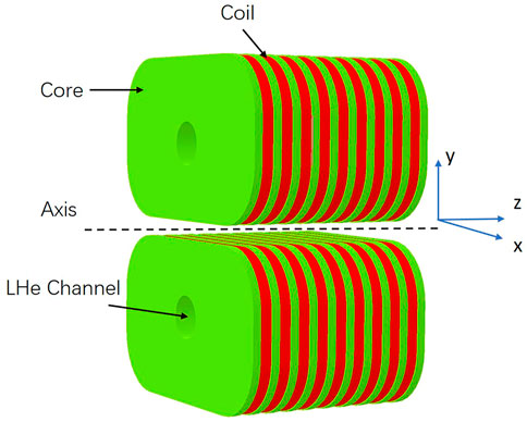
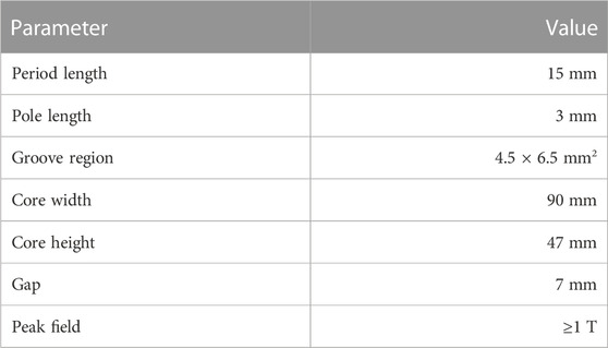
The SCU model is simulated using the OPERA-3D program. The magnet core is of a vertical racetrack type that enables a continuous coil winding scheme with a single strand. The size of the coil pack is designed to reach the target peak field on the axis, while the magnetic field in the conductors should be relatively small to allow a large load current. Figure 1 shows the 3D simulation model for the short SCU prototype and the coordinate axes defined for the model. The cores and poles are made of pure electric iron DT4, and each core consists of 4.5 periods with a period length of 15 mm. The coils are wound with round NbTi/Cu strands with 0.6 mm diameter. Each coil contains 72 turns of NbTi wires within 11 layers. The odd layers have seven turns of conductors, and the even layers have six turns of conductors. There is a cylindrical channel through the iron core which contains liquid helium for cooling the magnet in the cryostat. Table 1 lists the main parameters of the SCU.
The coil groove is 4.5 mm width in the z-direction and 6.5 mm deep in the y-direction. The adjacent grooves are separated by the pole with 3 mm width. The limit of the load current in the NbTi wire depends on the maximum magnetic fields and the temperature on the coils [12,13]. The simulation results show that the maximum current that can be applied to the coils is 629 A, with a corresponding peak field of 1.27 T, and the operation current is about 438 A to reach a 1 T peak field.
In the first two grooves at each end of the iron core, correction coils are wound in order to correct the first and second integrals of the magnetic field. The first and second magnetic field integrals are related to the beam trajectory angle and transverse position, respectively, as given in the following equations:
where e is the beam charge, γ is the relativistic factor, m0 is the electron rest mass, I1(z) is defined as the first integral of the magnetic field, and I2(z) is the second integral of the magnetic field. The main function of the correction coils is to optimize the field integrals with a suitable current. Figure 2 gives the magnetic field distribution and the corresponding field integral curves for a 0.5-m-long SCU simulation model with 0 A and 10 A correction currents, respectively. The figure shows that the first and second magnetic field integrals are optimized significantly.
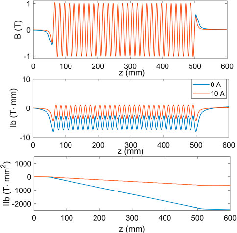
FIGURE 2. Magnetic field on the axis (top) and the corresponding first integral curves (middle) and second integral curves (bottom) with 0 A and 10 A correction currents, respectively, for a 0.5-m-long SCU model.
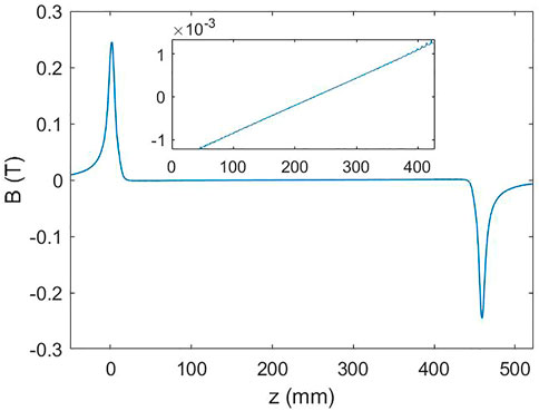
The difference curve between the magnetic fields with and without the correction current is plotted in Figure 3. The field caused by the correction coils mainly focuses on the two ends of the SCU, which can kick the beam and thus change the beam trajectory. The center field is approximate to a line through the undulator center, which can affect the field integral slightly and increase the magnetic field phase error.
We want to modify the local field of the 1.5-m-long SCU by adjusting the local magnetic gaps. In this case, the field deviation caused by the position errors of the poles and coils in the y-direction needs to be evaluated. Figure 4 shows the field error caused by a single pole or a single coil bundle with 0.2 mm displacement close to the beam axis. The black dashed curve indicates the reduced magnetic field on the axis with 341 A main current. The pole displacement induces a field error in the pole location, while the coil bundle displacement causes an antisymmetric disturbance of the magnetic field that mainly affects the two adjacent peaks. The amplitude of the field deviation is linearly dependent on the position error of the pole and coil bundle. Therefore, the gap adjustment of the SCU can be determined according to the difference in the peak fields.
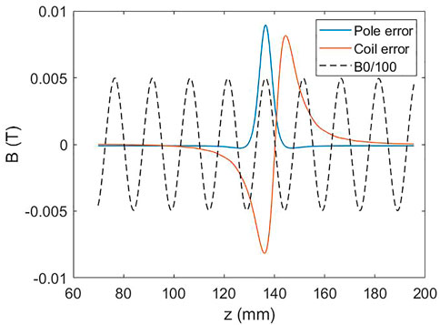
FIGURE 4. Field deviation caused by 0.2 mm displacement of a single pole and a single coil bundle. The black dashed curve indicates the ideal field whose amplitude was reduced to 1/100.
3 Short mock-up coils
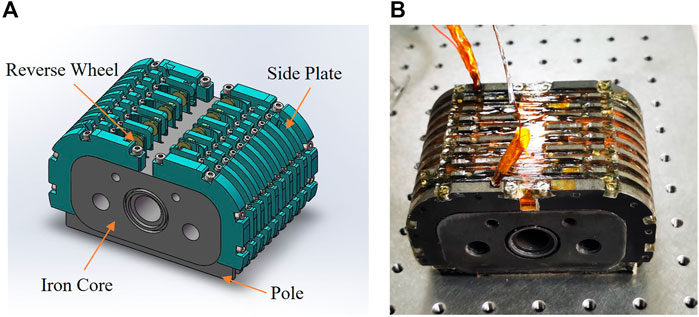
Several short mock-up coils were manufactured to study the processing technologies. The magnet mainly consisted of an iron core, poles, and side plates, as shown in Figure 5. The core made of DT4 was machined precisely as a whole component. Poles and side plates were processed independently and then inserted into the core. We tried two different materials to prepare the side plates: Al and G10. The Al side plates can enhance the capacity of heat transmission, while the G10 plates have better insulation performance. Reverse wheels were installed on the side plates to change the winding direction of the NbTi strand from one groove to the next. A continuous scheme with a single strand was achieved with the help of the reverse wheels. The coils were wound by Kapton to enhance the insulation behavior of the iron core. The coils-to-ground insulation can tolerate a voltage more than 2000 V. After coil winding, the short mock-up was epoxy-impregnated to fix the coil position during quench training. The short SCU structure and a mock-up after impregnation are shown in Figure 5.
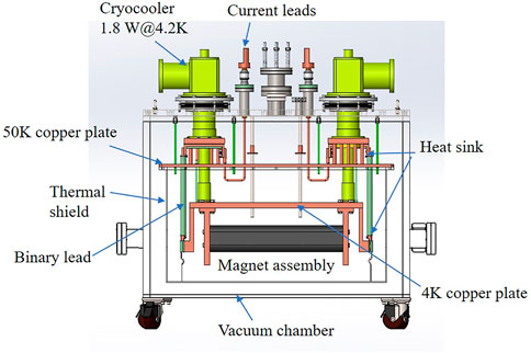
In order to reduce the high cost of the cryogenic test using liquid helium (LHe), a LHe-free cryostat was specially designed and fabricated. A structure diagram of the cryostat is presented in Figure 6. The cryostat was cooled by two G-M-type two-stage cryocoolers, which provided a cooling capacity of 3.6 W at 4.2 K. The heat declined, and magnet assembly in the cryostat can reach the target temperature through conduction cooling. The thermal shield was installed under the 50 K plate, which was connected to the first stage cryocoolers by copper strips. The second-stage coolers were connected to the 4 K plate, where the magnet was mounted. A pair of binary leads consisting of copper rods and high temperature superconductors (HTSs) was used to connect SCU coils and the power supply for loading the current. The HTS was installed between the 50 K and 4 K cold mass. The cold structure was surrounded by the vacuum box to reach the vacuum environment with the order of 10−5 Pa. The total heat load of the cryostat was about 0.34 W, which can be covered by cryocoolers [10]. Temperature sensors were mounted on special locations to monitor the cooling process. The short mock-up was cooled down to about 3.2 K after 15 h.
The short SCU was trained to increase the current loading ability. The maximum current in the mock-up coils reached 500 A within ten quenches [14]. A cryogenic hall probe was set in the undulator gap to measure the peak magnetic field on the axis. The relationship curve between the load current and the peak magnetic field was obtained, as given in Figure 7. The measured peak field reached 1 T at 460 A load current. In addition, the mock-up coils kept running at 450 A current for 5 h to verify the long-term stability.
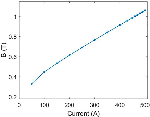
FIGURE 7. Relation curve between the peak magnetic field and the load current for short mock-up coils.
4 0.5-m-long SCU
After the production of the short SCU mock-up, we produced a 0.5-m-long SCU prototype. The structure of the long SCU was kept the same as the short SCU. For the SCU, the magnetic field quality was directly determined based on the precision of manufacturing and fabrication.
The height of the magnet poles for each iron yoke was measured using a three-coordinate measuring instrument, which was then assembled together as a 0.5-m-long SCU. The pole height RMS error was 25 μm for the first magnet yoke and 9.8 μm for the second magnet yoke [15]. Due to the poor manufacturing accuracy, the first magnet yoke had bad pole height consistency. The second one was produced more precisely to meet the tolerance requirement. The two magnet yokes were clamped together in a frame to ensure good alignment. Several blocks made of stainless steel were inserted into the gap to maintain the gap distance. There were two side railways installed in the gap to guide a copper sledge for carrying hall probes to measure the magnetic field during the cryogenic test. The gap was set at 7 mm to match the size of the guide rails.
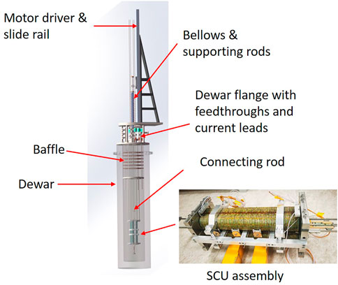
The 0.5-m-long SCU prototype was tested using a vertical test system [11], as shown in Figure 8. During the vertical test, the SCU was hung in a Dewar submerged in liquid helium to maintain the testing temperature at 4.2 K. The system was equipped with a motor-driven linear slide rail to pull the movable parts of the system. An L-shaped flange installed on the motor-driver slide was used to connect the bellows and pass the hall signals via the feed-through. The bottom of the bellows was connected to the Dewar flange. The travel of the bellows must be longer than the 1.5-m-long undulator. The bellows were specially designed to be supported by four external guide rods to avoid heavy bending during compression. A traction tube inside the bellows was used to connect the hall sledge and top flange of the bellows.
After quench training, the load current in the coils achieved 480 A, and the peak magnetic field reached 1 T at 450 A. We repeated the measurement four times to calculate the RMS errors of the peak magnetic field and half period length, which were
Correction coils were wound in the 0.5-m-long SCU to correct the first and second magnet field integrals. The correction coils were loaded with different currents to test the ability. Figure 9 shows the magnetic fields and the corresponding first and second integrals at 400 A main current with 0 A, 20 A, and 30 A correction currents, respectively. When the correction current was 20 A, the offset of the center part of the first magnet field integral shifted closer to the beam axis. Accordingly, the second integral was optimized from −3400 T⋅mm2 to −487 T⋅mm2. However, since the correction currents were not appropriately set, the magnetic field integrals were increased again.
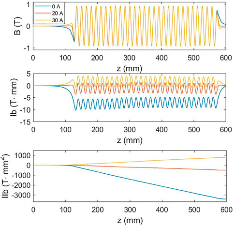
FIGURE 9. Magnetic field curves and the corresponding first and second field integrals at 400 A main current with 0 A, 20 A, and 30 A correction currents, respectively.
The simulation results also indicated that the center part of the magnetic field induced by the correction coils was small but not negligible. This can affect the phase error of the magnetic field, which is an important parameter to assess the field quality. The optical phase is determined by the phase slip between the electron beam and the emitted photon as given in Eq. 3.
where K is the deflection parameter, e is the electron charge, m is the electron mass, c is the light velocity, λu is the undulator period length, and θ is the launch angle to compensate for the initial kick at the entrance of the undulator.
The magnetic field of a real undulator is not a pure cosine function. The end field part, so-called fringe field, is much different from the regular peaks. Normally, the first three ending poles are regarded as the ending poles to be excluded in the phase calculation [16]. The phase error is calculated as the RMS error of the phase on each undulator pole. Figure 10 shows the pole phase curves of the 0.5-m-long SCU at 400 A main current and three different correction currents. The corresponding phase errors were 14.8°, 6.1°, and 8.2° for 0 A, 20 A, and 30 A correction currents, respectively. With a suitable correction current, the phase errors of the SCU are also corrected.
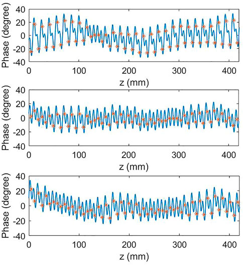
FIGURE 10. Phase maps for 400 A main current with 0 A (top), 20 A (middle), and 30 A (bottom) correction currents. The red markers indicate the phases on each undulator pole center.
5 1.5-m-long SCU
The R&D project aims to produce a 1.5-m-long SCU, which was achieved recently. The 1.5-m-long SCU was manufactured and assembled with the same scheme as the 0.5-m-long SCU. The gap of the 1.5-m-long SCU was set at 9.5 mm in order to fit the vacuum chamber installed in between the gap, when tested horizontally in the cryostat [17]. The two SCU yokes were also mounted on the end plates and clamped tightly on the gap plugs. The pole height RMS error of the two magnet yokes were under 10 μm.
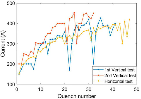
This prototype went through two rounds of the vertical test. During the first test, the load current reached 426 A after more than 40 quenches. However, the magnetic field measurement results showed a relatively bad field quality due to the large phase error, which was larger than the required tolerances of 10° for the project. In this case, the local field needs to be modified based on the peak magnetic fields. The local field can be changed at the places where the gap plugs are located. The peak field at each plug pair was obtained from the fitting curve of the peak fields. Then, the thickness of the blocks that is to be reduced was calculated according to the simulation results as described in Section 2. The absolute peak field distribution and the reduced thickness of the blocks are given in Figure 11.
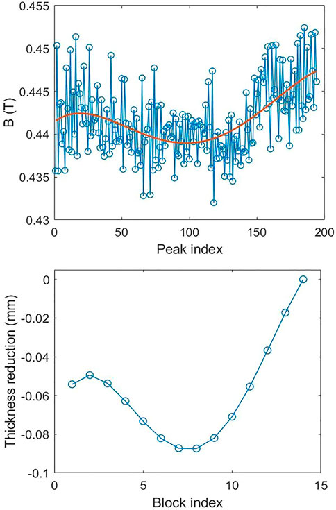
FIGURE 11. Absolute peak field distribution including the fitting curve (top) and the reduced thickness of the blocks (bottom).
After the gap adjustment, the SCU was vertically tested again. The phase error was reduced significantly. Figure 12 shows the phase distributions at the pole centers before and after the gap adjustment at 300 A main current with a suitable correction current for each measurement. After the gap adjustment, the phase RMS error was reduced from 18.7° to 6.0°. Furthermore for the measurement at 400 A main current, the phase error was calculated to be 8.3° with a suitable correction current.
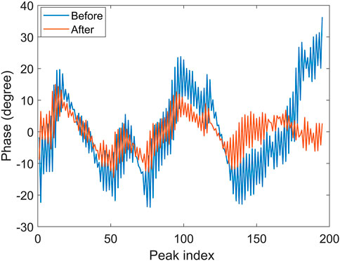
FIGURE 12. Phase maps for the 1.5-m-long SCU at 300 A main current before and after the gap adjustment.
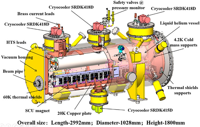
SCUs should be installed in a cryostat to be operated in accelerators. We designed a large cryostat to test the 1.5-m-long SCU under a horizontal installation condition as shown in Figure 13. This cryostat was equipped with four G-M-type two-stage cryocoolers, three at the top and one at the bottom. The thermal shields were cooled to about 60 K by the first stages of the four cryocoolers. The LHe vessel was connected to the second-stage cryocoolers at the top. The beam vacuum chamber in the undulator gap was cooled down to 20 K by the second stage of the bottom cryocooler. The SCU was cooled by the LHe flow, which was driven by the thermosiphon cooling loops, through the iron core channel. The cooling curves of the magnet core and the low temperature ends of the two current leads are shown in Figure 14. The three curves represent the temperature at the magnet core and the two current leads. It took about 7 days to cool the magnet down to the target temperature of 4.2 K.
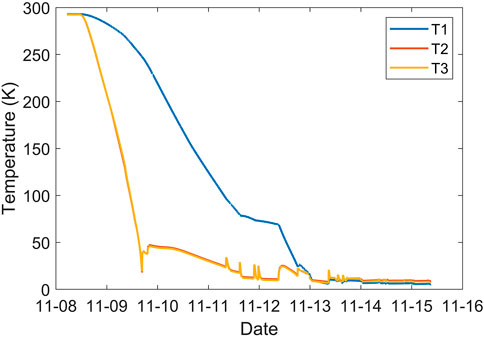
FIGURE 14. Cooling curves of the 1.5-m-long SCU in the cryostat. T1 for the magnet core; T2 and T3 for the two current leads.
During the horizontal test, the SCU still needs quench training to load the high current because the fabrication structure was far different from the vertical system that results in a band quench memory. Figure 15 gives the quench curves of the 1.5-m-long SCU for the vertical and horizontal tests. The horizontal test went through 48 quenches to reach a load current of 420 A. After the quench, the temperature of the magnet core rose about 9 K and took much more time to recover due to the weaker cooling ability of the LHe flow compare to the LHe immersion during the vertical test. After the quench training, the 1.5-m-long SCU was stably operated over a long time with a high load current. The future focus is to develop a horizontal magnetic field measurement system. The SCU needs to be adjusted based on the measurement result to achieve a good field quality.
6 Summary
This paper reviews the progress of NbTi planar SCU development at the IHEP. The project started by producing several short mock-up coils to verify the feasibility of the producing technologies. These short SCUs were tested in a free LHe cryostat to reach the maximum current loading ability. After the quench training, the current in the coils achieved 500 A, and the peak magnetic field exceeded 1 T at a 6.5 mm gap.
The second stage of the project was manufacturing a 0.5-m-long SCU prototype. The long SCU structure and the coil winding scheme were kept the same as the short mock-up. After fabrication, the SCU was cryogenically tested using a vertical test system by hanging it in a Dewar submerged in liquid helium. The magnetic field measurement system for the vertical test had a repeated accuracy of
Manufacturing a 1.5-m-long SCU was the final target of our R&D project. Currently, a prototype has been produced and cryogenically tested. The SCU was vertically tested twice. After the first test, we applied the gap adjustment method to change the local field for optimizing the phase error, which was reduced below 9° with 400 A main current during the second vertical test. Recently, this 1.5-m-long SCU was installed in a large cryostat and was successfully cooled down to the target temperature of 4.2 K. The maximum load current reached 420 A, and the SCU can stably operate in the cryostat at a high current for a long time. The measurement system to be used in the cryostat is under development. Based on the measurement result, the SCU can be adjusted under the horizontal condition to meet the requirement of the magnetic field quality in the cryostat.
Data availability statement
The raw data supporting the conclusion of this article will be made available by the authors, without undue reservation.
Author contributions
JW: magnet design and simulation, experimental setup and data analysis, and writing—original manuscript and revision. YL: conceptualization, supervision, and reviewing. XY: mock-up coil manufacture and testing and reviewing. XZ: cryostat design and manufacture and reviewing. XB: quench protection system design and testing. ZC: magnet assembly, measurement, and reviewing.
Acknowledgments
The authors thank their colleagues for the valuable suggestions to their project during the SCU production and the vertical test. They also acknowledge the support of the National Natural Science Foundation of China (E1113R5C10 and E029A5M111).
Conflict of interest
The authors declare that the research was conducted in the absence of any commercial or financial relationships that could be construed as a potential conflict of interest.
Publisher’s note
All claims expressed in this article are solely those of the authors and do not necessarily represent those of their affiliated organizations, or those of the publisher, the editors, and the reviewers. Any product that may be evaluated in this article, or claim that may be made by its manufacturer, is not guaranteed or endorsed by the publisher.
References
1. Bahrdt J, Gluskin E. Cryogenic permanent magnet and superconducting undulators. Nucl Instrum Methods Phys Res Sect A (2018) 908:149–68. doi:10.1016/j.nima.2018.03.069
2. Bahrdt J, Ivanyushenkov Y. Short period undulators for storage rings and free electron lasers. J Phys Conf Ser (2013) 425:032001. doi:10.1088/1742-6596/425/3/032001
3. Zhang K, Calvi M. Review and prospects of world-wide superconducting undulator development for synchrotrons and fels. Supercond Sci Technol (2022) 35:093001. doi:10.1088/1361-6668/ac782a
4. Huang CS, Jan JC, Chang CS, Chen SD, Chang CH, Uen TM. Development trends for insertion devices of future synchrotron light sources. Phys Rev ST Accel Beams (2011) 14:044801. doi:10.1103/physrevstab.14.044801
5. Casalbuoni S, Glamann N, Grau A, Holubek T, Saez de Jauregui D, Bauer S, et al. Superconducting undulators: From development towards a commercial product. Synchrotron Radiat News (2018) 31:24–8. doi:10.1080/08940886.2018.1460171
6. Kasa M, Anliker J, Fuerst Q, Hasse I, Kesgin Y, Shiroyanagi E, et al. Superconducting undulators for the advanced photon source upgrade. Proc Ipac2019 (2019). 1884–6. doi:10.18429/JACoW-IPAC2019-TUPRB095
7. Ivanyushenkov Y, Harkay K, Abliz M, Boon L, Borland M, Capatina D, et al. Development and operating experience of a short-period superconducting undulator at the Advanced Photon Source. Phys Rev ST Accel Beams (2015) 18:040703. doi:10.1103/physrevstab.18.040703
8. Xu JP, Zhou Q, Yin L, Ding Y, Wang S, Li M, et al. Development of a superconducting undulator prototype at the SSRF. IEEE Trans Appl Supercond (2017) 27:1–4. doi:10.1109/tasc.2016.2632758
9.Dassault System. Opera: Electromagnetic and electromechanical simulation (2021). Available at: https://www.3ds.com/products-services/simulia/products/opera/.
10. Zhang X, Xu M, Yang X, Bian X, Chen Z, Wei J, et al. Development of liquid helium-free cryostat for a superconducting undulator. Nucl Instrum Methods Phys Res Sect A (2023) 1049:168037. doi:10.1016/j.nima.2023.168037
11. Chen Z, He P, Li Y, Yang X, Wei J, Zhang X, et al. Magnetic field measurement system in vertical status for superconducting undulator cooled in Dewar. JINST (2022) 17:T09008. doi:10.1088/1748-0221/17/09/t09008
12. Casalbuoni S, Gerstl S, Glamann N, Grau A, Holubek T, Saez de Jauregui D, et al. Test of short mockups for optimization of superconducting undulator coils. IEEE Trans Appl Supercond (2015) 24:1–5. doi:10.1109/tasc.2013.2295921
13. Karasev YV, Pantsyrny VI, Polikarpova MV, Lukianov PA, Potanina LV, Baumgartner T, et al. Jc(B, T) characterization of commercial NbTi stands for the ITER poloidal field coils by transport and magnetization methods. IEEE Trans Appl Supercond (2013) 23:6001304. doi:10.1109/tasc.2013.2243811
14. Wei J, Yang X, Zhang X, Chen Z, Bian X, Xu M, et al. Development and cryogenic test of superconducting undulator mock-up coils at ihep. Nucl Instrum Methods Phys Res Sect A (2022) 1034:166822. doi:10.1016/j.nima.2022.166822
15. Wei J, Li Y, Yang X, Chen Z, Zhang X, Bian X. Development and magnetic field measurement of a 0.5-m-long superconducting undulator at IHEP. J Synchrotron Rad (2022) 29:997–1003. doi:10.1107/s1600577522006166
16. Li Y. Definition and calculation of the optical phase to the undulator. European XFEL Report (2011). No.WP71-2011-19.
Keywords: superconducting undulator, NbTi, free-electron laser, vertical test, phase error
Citation: Wei J, Yang X, Chen Z, Zhang X, Bian X and Li Y (2023) Development of NbTi planar superconducting undulators at the IHEP. Front. Phys. 11:1153005. doi: 10.3389/fphy.2023.1153005
Received: 28 January 2023; Accepted: 23 March 2023;
Published: 05 April 2023.
Edited by:
Nicholas Walker, Helmholtz Association of German Research Centres (HZ), GermanyReviewed by:
Gianluca Ghigo, Polytechnic University of Turin, ItalyWinni Decking, Helmholtz Association of German Research Centres (HZ), Germany
Copyright © 2023 Wei, Yang, Chen, Zhang, Bian and Li. This is an open-access article distributed under the terms of the Creative Commons Attribution License (CC BY). The use, distribution or reproduction in other forums is permitted, provided the original author(s) and the copyright owner(s) are credited and that the original publication in this journal is cited, in accordance with accepted academic practice. No use, distribution or reproduction is permitted which does not comply with these terms.
*Correspondence: Yuhui Li, bGl5dWh1aUBpaGVwLmFjLmNu
 Junhao Wei
 Xiangchen Yang2
 Zilin Chen
 Xiangzhen Zhang