- 1SLAC National Accelerator Laboratory, Menlo Park, CA, United States
- 2Helmholtz-Zentrum Dresden Rossendorf, Dresden, Germany
Various continuous-wave (CW) electron gun technologies are reviewed, including DC, superconducting radio frequency RF (SRF), hybrid DC-SRF and normal-conducting RF. Also, the SLAC Linac Coherent Light Source II (LCLS-II) normal-conducting RF gun and injector are described, and the performance to date, including the bunch emittance achieved and the dark current observed, is presented.
1 Introduction
X-ray free electron lasers (XFELs) [1–4] have proven to be a revolutionary tool for scientific studies of material properties. However, existing XFEL facilities typically operate at repetition rates below a few hundred Hertz (Hz) due to power handling limitations of their normal-conducting guns and accelerator structures. To push to photon science Frontier, MHz rate beams are needed with continuous-wave (CW) radiofrequency (RF) operation. One of the major challenges for such MHz XFELs is to find a CW electron gun technology that can produce high-brightness electron bunches.
CW gun R&D has been pursued worldwide since the 1980s. The gun technologies include DC [5–8], Superconducting RF (SRF) [9–18], hybrid DC-SRF [19] and normal-conducting (NC) RF [20, 21]. This paper first surveys these technologies and then discusses the design and performance of the NC RF gun and injector at the SLAC Linac Coherent Light Source II (LCLS-II). Finally, the performance of representative guns is summarized.
2 CW gun development
Significant progress has been made for each gun technology noted above [22–24]. The labs that have been involved are listed below and more information is provided in the following subsections.
DC gun
• Cornell University in the United States of America [5, 6].
• Daresbury Laboratory in the United Kingdom [8].
• JAEA/KEK in Japan [7].
Hybrid DC-SRF gun
• Peking University in China [19].
SRF gun with 1.3 GHz Elliptical Cells
• Helmholtz-Zentrum Dresden-Rossendorf (HZDR) in Germany [11].
• Helmholtz-Zentrum Berlin (HZB) in Germany [12].
• DESY in Germany [13].
• KEK in Japan [14].
SRF gun with 100–200 MHz Quarter-Wave Resonator (QWR) cavity
• Wisconsin University in the US [15].
• BNL in the US [16].
NC gun (185.7 MHz)
A version of the LBNL NC gun is currently being used at LCLS-II and will be used at the Shanghai XFEL facility [25]. The SLAC/MSU/HZDR 185.7 MHz SRF gun is currently being developed for use in a low projected emittance (∼0.1 μm) injector that has been proposed for the high energy upgrade of LCLS-II (LCLS-II-HE).
2.1 DC guns
The DC guns have been developed for high current Energy Recovery Linac (ERL) applications. The Cornell DC gun is the most advanced and can routinely operate with a 400 kV cathode-to-anode potential, which produces a ∼4.4 MV/m gradient at the photocathode. It has successfully produced 75 mA low-emittance beams, which is a world’s record for average current [5]. Green light photocathodes (e.g., K2CsSb, NaKSb) are typically used and the dark current is generally negligible.
At Cornell, 100 pC bunches with an emittance of about 0.4 μm [6] have been produced with ten’s-of-ps-long flattop-like laser pulses. However, because the flattop-like laser pulses were obtained through stacking ps-level short pulses, a small intensity modulation on the flattop is generated, which can be significantly amplified after the ∼100 times bunch compression required for XFELs, thereby compromising the longitudinal phase space [26]. Thus, smooth Gaussian temporal laser pulses are typically used for XFELs although the transverse emittance is not optimum compared to that achievable with a stacked laser pulse.
The 400 kV gun voltage is near the high voltage limit without major advances in high voltage insulator and electrode materials. The relatively low gradient on the cathode and the low gun energy that results limit the ultimate electron peak current after bunch compression. Preliminary simulations [27] have shown that the peak bunch current is notably limited after two stages of bunch compression due to the highly non-linear energy spread.
2.2 Superconducting RF guns
SRF guns are promising candidates for CW operation with at least 30 MV/m of gradient at the photocathode and energy gains of a few MeV. There are two main categories of SRF guns in use: one uses 1.3 GHz elliptical cells, for example, those developed by HZDR, HZB, KEK and DESY, while the other uses 100–200 MHz single-cell QWR cavities, and have been, or are being developed by U. of Wisconsin, BNL and a SLAC/MSU/HZDR collaboration.
Among the first category of guns, the DESY 1.6 cell SRF-Gun has a metallic photocathode (niobium plug coated with lead, which becomes superconducting below 7.2 K) that attaches to the cavity half-cell shorting plate. Thus, no in-situ photocathode exchange is possible and no loadlock system is required. The quantum efficiency of the lead photocathode is about 2 orders lower than that for the semiconductor photocathodes used in most CW guns, which imposes a challenge for MHz-rate electron beam operation. The gun has achieved a 40 MV/m gradient at the photocathode based on vertical test [13, 24].
The HZDR, HZB and KEK guns use removable semiconductor photocathodes that are thermally isolated from the niobium cavity and include a choke cell to limit RF leakage into the gap between the cathode stalk that holds the photocathode and the niobium. Their cryostats contain a superconducting solenoid magnet for emittance compensation, and there is an upstream load-lock system for warm photocathode exchange.
The HZDR 1.3 GHz SRF gun with a Mg photocathode began routine operation in 2017 as part of an accelerator for Tera Hertz (THz) RF production [11]. Cs2Te photocathodes were tested in 2020 [28] but strong QE degradation occurred soon after CW RF operation began. Currently, the gun is operating in CW mode with a 14 MV/m of gradient at the photocathode for the user program, and typically produces bunch charges of 200 pC at 50–100 kHz. The bunch transverse emittance is ∼3 µm and the rms bunch length is 300 fs after the linac and chicane, which meets the THz program requirements. The L-Band gun has the potential to provide a higher gradient at the photocathode, but it is currently gradient limited due to cavity contamination from a photocathode failure in 2017.
BNL developed their QWR SRF gun for an electron cooling project. The gun consists of a 112 MHz QWR cavity with a warm photocathode, which can be exchanged via a load-lock system under ultra-low vacuum pressure. The gun is typically operated with a photocathode gradient of 15–18 MV/m. A low intrinsic emittance green light photocathode (K2CsSb) is used, whose lifetime benefits from the low vacuum pressure afforded by the cryogenic environment. An emittance of about 0.3 μm has been demonstrated for 100 pC bunches but with a very long bunch length (∼400 ps), more than 100 times longer than that required for XFELs.
The SRF guns have common challenges including.
• Complex/fragile photocathode exchange systems, which can readily cause gun contamination/degradation during photocathode insertion into the gun body
• Non-optimal emittance compensation
• Much lower-than-expected gradient on the photocathode with the photocathode inserted.
The need to keep the photocathode plugs from contacting the cold cavity walls creates complexity for the SRF gun design and operation. The compatibility of SRF cavities with insertable photocathodes remains a challenge for robust SRF gun operation, particularly when frequent photocathode exchanges are required, which can introduce particulates. Also, semiconductor photocathodes pose a contamination risk from the diffusion/sputtering of their chemical components during operation. Contaminants can create field emission on the cavity surface that results in significant performance degradation due to dark current generation and enhanced secondary electron emission. BNL finds that in-situ helium processing helps recover from such degradation [29] although the cleaning process is not-trivial.
A solenoid magnet is typically used just downstream of the gun as part of a compensation process to reduce space charge related emittance growth. SRF guns have a notable drawback in this regard as the magnetic field on the niobium cavity surfaces must be kept lower than the critical magnetic field. As a result, the solenoid must be located farther away from the cathode in an SRF gun cavity, which can compromise emittance compensation compared to a NC gun. This distance is longer for 3.5-cell 1.3 GHz SRF guns than for a QWR SRF gun, which is disadvantageous for producing the sub-micron emittance bunches required for XFELs [30, 31].
To date, SRF guns have not routinely demonstrated e-beam operation with >20 MV/m gradient on photocathode. Multipacting and particle-contaminant-induced field emission are the major factors limiting the gradient. However, there are ongoing SRF gun R&D programs that are pursuing higher than 30 MV/m of gradients on the photocathode for e-beam operation [12–14, 17, 18].
2.3 Hybrid DC-SRF gun
A DC-SRF gun has been under development by Peking University for about 3 decades. It has evolved to combine a 100 kV DC cell (5 MV/m of gradient on the photocathode) and a 1.3 GHz, 13 MV/m, 1.5-cell SRF cavity. They are connected by a drift tube that is about 1 cm long, and the resulting energy gain is 2.2 MeV. With the DC cell, the photocathode is moved out from the cryogenically cooled cavity, which lessens the compatibility issues noted above. The emittance compensation solenoid is in a warm beamline section that is about 0.5 m downstream of the cavity. K2CsSb photocathodes are used, and recently sub-micron emittances have been achieved with 50–100 pC bunches generated by stacked laser pulses [19]. The dark current is small (pA level) and the bunch length has yet to be measured.
2.4 NC RF guns
High-frequency (>1 GHz), high gradient NC RF guns are being used to produce high-brightness beams for pulsed XFELs. The average power loss density in such cavities limits the practical repetition rate to less than 1 kHz. By decreasing the RF frequency to hundreds MHz, the size of the cavities increases with a beneficial reduction of the power density, allowing higher duty RF operation [32, 33].
In 2006, a LBNL team proposed and later developed [20, 34] a 186 MHz CW QWR NC RF gun for high repetition rate XFELs. The power load on the cavity walls at the nominal 20 MV/m of gradient on photocathode is removed by conventional cooling techniques. Good vacuum (∼10−10 Torr) is achievable and long lifetime operation with Cs2Te photocathodes has been demonstrated, but practical lifetimes with K2CsSb photocathodes have yet to be realized. An emittance of 0.25 μm has been achieved with 20 pC bunches [21] but μA level dark current has been an issue [35]. Given the good performance with Cs2Te photocathodes, the gun design was adopted for LCLS-II.
3 LCLS-II gun systems
This section provides an overview of the LCLS-II CW electron injector and summarizes the beam performance and the dark current measurements and mitigations.
3.1 Layout and parameters
The LCLS-II electron source, which comprises the first 3 m of the injector, was designed and built by the LBNL following their decade-long advanced photoinjector experiment (APEX) program to develop a 186 MHz NC, CW electron gun [20, 21, 34, 35]. For the LCLS-II project, modifications to the gun design were made based on lessons learned and specific LCLS-II requirements.
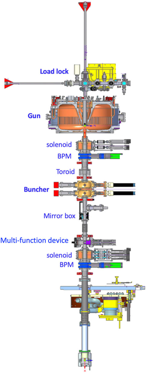
Figure 1 shows a schematic layout of the electron source, which includes a 185.7 MHz QWR-style CW NC RF gun, a 1.3 GHz two-cell NC cavity for compressing the bunch length, and two solenoid magnets for beam focusing and emittance compensation. Beam diagnostics include two beam position monitors (BPMs), a current monitor (toroid), and a newly installed multi-function insertion device that contains 4 circular collimators with different aperture sizes, an yttrium-aluminum-garnet (YAG) screen, and a YAG screen with a central hole. Electrons lost on the circular collimator plates are detected by a pico-ammeter, which serves to monitor gun dark current. A load lock for photocathode exchange is located upstream of the gun and mirror box is located 1.1 m downstream of the photocathode for injecting 257.5-nm-wavelength laser pulses. Cs2Te photocathodes produced at SLAC are being used for bunch charge generation.
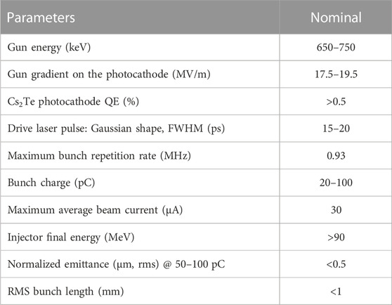
Following the electron source is 1) a standard LCLS-II cryomodule, which has eight 9-cell cavities to boost the electron energy to more than 90 MeV, 2) an emittance station including four matching quads and a screen, 3) a laser heater chicane that increases the bunch slice energy spread to suppress micro-bunching, 4) two cavity-based average current monitors to measure electron beam current and dark current, and 5) a dedicated off-axis beamline for emittance and bunch length measurements. The LCLS-II electron source and injector parameters are summarized in Table 1.
3.2 NC RF gun and buncher systems
The single-cell gun cavity is designed for CW RF operation at 185.7 MHz, the seventh subharmonic of the 1.3 GHz superconducting linac frequency. The cavity has an R/Q of 198.2 Ω, a Q0 of 29,923, and two RF power coupling ports with a combined coupling coefficient of 1.1. The design gun voltage gain is 750 kV, but the gun is typically run with a voltage gain of ∼650 kV, corresponding to a photocathode gradient of ∼17.5 MV/m. The RF connection to each of the two-gun ports consists of an air-to-vacuum window followed by a 90° bend that terminates in a loop coupler, all implemented in coaxial waveguide. The bend keeps dark current from the gun interior from directly hitting the vacuum window. In each feed line, three permanent solenoid magnets are installed in the short section between the RF coupler and the vacuum window to suppress multipacting. Light detectors that view the rf windows and gun body will shut off the RF in the event of an arc, but none has occurred yet.
Each gun port is powered by a 60 kW solid state amplifier (SSA). The SSA output power is very stable in open loop, about 0.01% rms in amplitude and 0.1° rms in phase on a 1-s timescale [36]. The SSAs are installed in the SLAC linac gallery, and 6.125-inch rigid coaxial waveguide is used to transport the RF power from the SSAs to the gun in the linac tunnel. Although the SSA transistors are back terminated, high-power isolators are included in the transport lines in the gallery. For non-ionizing radiation safety, the gallery waveguide is pressurized at a few pounds per square inch, which requires the use of coaxial air barriers. The RF will shut off if there is a drop in pressure inside the waveguide.
The gun vacuum is maintained by six non-evaporable getters (NEGs) and six combined NEGs and ion pumps that are located around the outer cavity radius and connect to a cylindrical structure that is cut off to the RF. A vacuum pressure in the low 10−9 Torr scale, and a partial pressure of less than 10−11 Torr for specific harmful molecules like oxygen, are required to achieve reasonably long lifetimes of the Cs2Te photocathodes used in the gun. The gun is cooled via five separate water circuits that connect to the SLAC 30 °C low-conductance water system. The combined flow is about 40 gallons-per-minute, and the flow through the anode plate was adjusted so the steady-state cavity frequency was in a range that did not overstress the mechanical tuners.
The RF buncher [37] is a two-cell, p-mode, 1.3 GHz NC cavity with R/Q = 340 Ω and Qo = 25,700. It has four input power couplers with a combined coupling coefficient of unity. The cavity adds an energy chirp to the bunches and the resulting velocity variation compresses the bunch length by a factor of 3–5. Each input coupler is powered by an independent SSA. For the nominal combined input of power of 7.6 kW, the integrated buncher field voltage is measured to be about 200 kV.
3.3 Gun and buncher frequency tuners
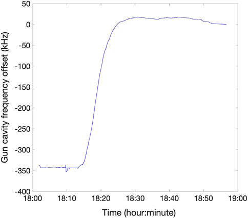
With the large size of the gun cavity, there is a substantial frequency change due to RF heating, about 250 kHz, which is much larger than the 6 kHz cavity half-bandwidth. A system of four mechanical tuners is used to pull the anode plate outward to adjust the cavity frequency. For each tuner, a DC motor rotates a shuttle that screws onto a bolt connected to the anode plate. When the gun warms up, the anode plate bows outward, and the reactive force on the shuttle disk is transferred through a piezo actuator and load cell to a thick plate that is attached to the outer rim of the gun anode. The load cells provide a measure of the applied force. During the warm-up period, the Low Level RF system first employs a self-excited loop controller to track the cavity frequency until the anode temperature begins to stabilize, then the tuners are used to set and maintain the cavity frequency near the nominal 185.714 MHz value. Figure 2 shows an example of the initial gun cavity frequency evolution when the RF duty factor was ramped to near 100%.
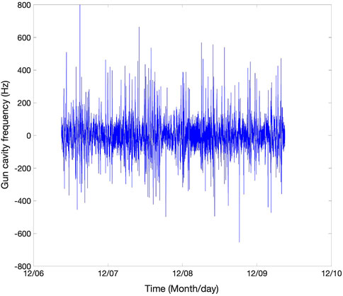
The frequency feedback system uses a two-tiered control loop in which a high-level feedback loop adjusts the tuner load cell set points based on the detuning relative to the nominal frequency, and four low-level feedback loops regulate the four tuner loads to their set point values. This control is critical as there is a subsequent −100 kHz frequency drift over a 4-h time period due to the slow heating of the outer cavity wall, which otherwise would pull the anode plate inward. During this period, the duty cycle is increased to 100% and cavity frequency is then computed based on the phase difference between the forward and probe signal RF. This control procedure typically regulates the frequency to within ±200 Hz of the nominal value, which is ∼ ± 3% of the cavity half-bandwidth. However, there are occasional larger frequency jumps when one of the tuner screws overcomes a frictional barrier. Figure 3 shows an example of the frequency regulation over a several-day period.
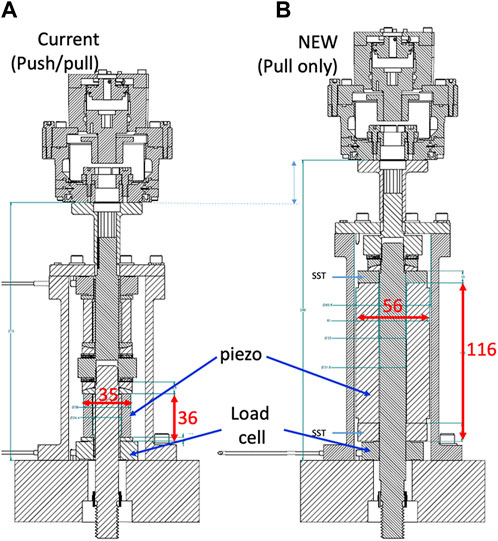
The four piezo actuators were originally meant to be used for fine frequency control, but they were damaged by radiation. Further investigation revealed that the piezos are readily radiation damaged when several hundred volts are applied for control. Upgrades to the tuner piezo system are underway, which should allow them to be used to improve the frequency regulation. Figure 4 shows schematics of the current and new tuners. The new piezo ceramic is 116 mm long and has a 56 mm outer diameter [38], making it considerably stronger than the original ceramic, which is 36 mm long with a 35 mm outer diameter. The new piezos are expected to require only one-fifth of the voltage of the original ones for same force generation, which should significantly extend their lifetimes.
The process for buncher cavity frequency tracking during warm-up and subsequent frequency locking is similar to that for the gun except the cavity frequency is controlled by adjustments to the temperature of the cooling water, which is provided by a closed-loop chiller. The RF heating detunes the cavity by about 600 kHz, much larger than its 50 kHz half-bandwidth. The cavity frequency is regulated to within 2 kHz of the nominal 1.3 GHz frequency using a PID temperature controller where the setpoint changes are proportional to the measured frequency offset.
3.4 Beam measurements
During the past year, the Cs2Te photocathodes used in the gun are ones produced at SLAC, which have an initial QE of about 5%. Low charge (<1 pC) emittance measurements indicate the intrinsic emittance of Cs2Te photocathodes is about 1 μm/mm-rms [39] with a 258 nm UV laser, which is close to that expected.
The laser pulses at the photocathode are shaped to be roughly uniform in their transverse profile although the emittance can be likely improved using a truncated Gaussian profile [40]. A smooth Gaussian-like temporal laser shape is used as it is much easier to generate than a smooth flat pulse. However, efforts are underway to generate flat pulses as they should yield a lower emittance after space charge compensation.
The bunch emittance is measured using the conventional quadrupole-scan technique. The bunch sizes are measured at the first screen after the cryomodule, which currently increases beam energy to 80 MeV. The gun is currently operated with lower voltage gain (650 kV) than the design value (750 kV) to reduce dark current. Simulations suggest that the emittance is not compromised at this lower voltage. Trim-quad (both normal and skew quads) coils that are embedded in the two main solenoids play an important role in correcting for high-order fields in the solenoids and in the 1.3 GHz SRF cavity power couplers [41, 42]. Adjustment of these trim-quads are seen to improve the bunch shape and results in a lower emittance. Currently, the buncher is operated with a voltage gain of about 200 kV and a phase such that the bunches arrive −30° from the zero-crossing.
The emittance compensation process is particularly sensitive to the settings of the first and third cavities in the cryomodule: the second cavity is not powered by design. After optimization of the various parameters, an emittance of about 0.5 μm has been routinely achieved so far for 50 pC bunches, which is somewhat larger than the ∼0.4 μm simulated values.
The bunch length is measured with the well-known RF zero-phasing technique [43]. A large bunch energy chirp is added by operating the seventh cryomodule cavity near the zero crossing. This streaks the bunch in the off-axis diagnostics line where there a large vertical dispersion, and the bunch length is inferred from the vertical bunch size as measured on a screen. Bunch length values of about 1 mm rms have been measured, which are close to expectation. Systematic optimization of the emittance and bunch length is still in progress.
3.5 Dark current measurements and mitigation
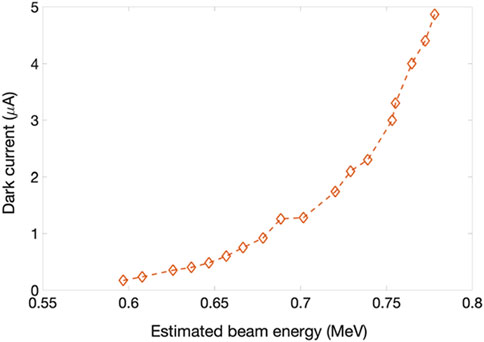
The CW NC RF gun generates several μA of dark current that appears to originate from localized areas on the rim of the cathode plug hole, which is 10 mm in diameter [35, 39]. Figure 5 shows the dark current measured 3 m from the cathode as function of beam energy (the cryomodule was not installed at this time). Such large dark current, if transported through the 4 GeV SRF linac to the XFEL undulators, will degrade the permanent magnets used in these devices.
As the dark current is well separated from the photobeam transversely [39], a circular collimator was installed to intercept it while the electron energy is low (<1 MeV) and thus the radiation produced is minimized. For this purpose, a ladder-like multi-function insertion device was designed and installed 1.5 m from the cathode [44]. This device includes four circular collimators with different aperture sizes (referred to as ‘LEB’ collimators), a YAG screen, and a YAG screen with a central hole to allow beam halo measurements (see Figure 6).
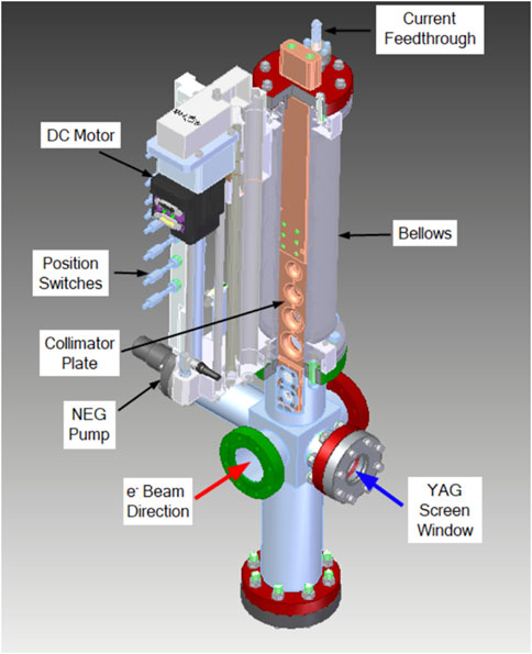
FIGURE 6. Ladder-like multi-function beamline insertion device that includes four circular collimators and two YAG screens.
An operator can remotely insert any one of the four LEB collimators, whose aperture sizes are 12, 16, 20 and 24 mm. The holes are machined in a 1.5 cm thick copper bar. The collimating function works well with the 20 mm aperture, which is sufficient to block the majority of the dark current while having a negligible impact on the photobeam. The copper bar is electrically isolated and connected to a pico-ammeter to monitor the intercepted current. Figure 7 shows an example of the measured dark current for different collimator settings when the gun energy gain was about 650 keV. More than 85% of the dark current is blocked with the 20 mm collimator.
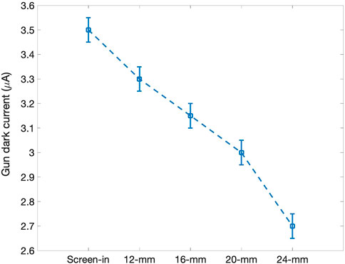
FIGURE 7. Dark current measured 1.5 m from the cathode with different LEB collimator sizes. For the ‘Screen-In’ case, a thin YAG screen intercepts the full current.
The remainder of the dark current is accelerated through the cryomodule where it incurs losses due to the large energy spread it develops. It is further attenuated by a 12-mm diameter circular collimator (denoted ‘PC0H00’) located just downstream of cryomodule. The dark current loss on this collimator is estimated from the temperature rise of the water used to cool it. The transmitted dark current is measured downstream with an RF-cavity-based average current monitor (ACM). Figure 8 shows the dark current loss and transmission as a function of the strength of the solenoid magnet just after the gun (Solenoid-1). This solenoid affects the transverse separation of the dark current and photobeam at the LEB collimator and hence the effectiveness of the collimation there. As the Solenoid-1 strength is usually larger than 0.0435 kG-m for optimum emittance, only 10s nA of dark current make it through the ACM. This current is further attenuated by downstream collimators. Dark current tracking simulations are being performed to better optimize the collimation [45].
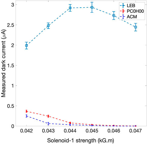
FIGURE 8. Measured dark current at the 20-mm LEB collimator and the PC0H00 collimator, and the dark current transported through an ACM as function of the strength of Solenoid-1.
Figure 9 shows the region on the copper cathode nose where the dark current is believed to originate. The electric field there is about 24% higher than that at the center of the plug [39]. At SLAC, a spare gun is being built that includes improvements for dark current reduction. One change is to make the cathode and anode opening edges elliptically shaped instead of round, and another is to add stainless steel (SS) inserts near the cathode and anode openings (see Figure 10) [46]. Using a minor-to-major axis ratio of 0.17 for the cathode plug and nose edges reduces the electric field enhancement from 24% to 10%. The SS inserts should increase the gradient of dark current onset. The spare gun fabrication is expected to be completed by the end of 2023.
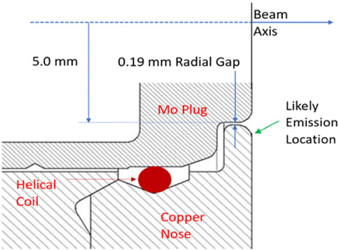
FIGURE 9. Cross section of the molybdenum cathode plug when inserted into the copper cathode nose. The likely dark current emission region is indicated.

FIGURE 10. Improvements to the spare gun (A) elliptical shaped (b/a=0.17) edges on the cathode plug and nose, (B) stainless steel (SS) inserts at the cathode and anode openings.
4 Summary
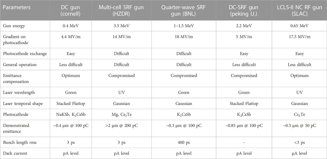
This paper has reviewed the four major CW gun technologies being developed for FELs and ERLs. Each technology has its advantages and disadvantages. The Cornell DC gun has produced 100 pC bunches with about 0.4 μm emittance although the longitudinal phase space may not be suitable for XEFL applications. As for ones using SRF technology, the BNL QWR SRF gun has achieved a 0.3 μm emittance with 100 pC bunches but with a bunch length more than 100 times longer than that required for XFELs, the HZDR SRF gun has routinely operated for a THz user program but has not yet demonstrated sub-micron emittance. And the DESY SRF gun with a superconducting lead photocathode can operate at higher gradients but the quantum efficiency is very low (<1 × 10⁻³). With a unique hybrid design, the Peking University DC-SRF gun has produced sub-micron emittance bunches, but the bunch length has yet to be characterized. Recently the LCLS-II NC RF-gun-based injector has routinely achieved 0.5 μm emittance for 50 pC bunches with the desired bunch length, and dark current mitigations that were implemented have been effective. Table 2 summarizes representative CW gun achieved parameters and challenges.
Author contributions
FZ drafts the paper and contributes to LCLS-II gun measurements, CA contributes to SRF section and LCLS-II gun analyses, DD contributes to LCLS-II gun analyses, and RX contributes to SRF section.
Funding
This work is supported by DOE under Grant Nos. DE-AC02-76SF00515.
Acknowledgments
We thank the LCLS-II injector commissioning team as well as the LBNL APEX group for their technical contributions and support, particularly X. Liu for excellent engineering support. We also thank S. Huang for providing supporting materials.
Conflict of interest
The authors declare that the research was conducted in the absence of any commercial or financial relationships that could be construed as a potential conflict of interest.
The reviewer DB declared a shared affiliation with the author RX at the time of review.
Publisher’s note
All claims expressed in this article are solely those of the authors and do not necessarily represent those of their affiliated organizations, or those of the publisher, the editors and the reviewers. Any product that may be evaluated in this article, or claim that may be made by its manufacturer, is not guaranteed or endorsed by the publisher.
References
1. Emma P, Akre R, Arthur J, Bionta R, Bostedt C, Bozek J, et al. First lasing and operation of an ångstrom-wavelength free-electron laser. Nat Photon (2010) 4:641–7. doi:10.1038/nphoton.2010.176
2. Ackermann W, Asova G, Ayvazyan V, Azima A, Baboi N, Bähr J, et al. Operation of a free-electron laser from the extreme ultraviolet to the water window. Nat Photon (2007) 1, 336–42. doi:10.1038/nphoton.2007.76
3. Tanaka H, Status report on the commissioning of the Japanese XFEL at SPRING-8, In: Proceedings of the 2nd International Particle Accelerator Conference (2011) San Sebastián, Spain (EPS-AG, Spain). 21.
4. Braun H, Commissioning of the Swiss FEL. In: Proceedings of the 8th International Particle Accelerator Conference (IPAC 2017); Copenhagen. Geneva: JACoW (2017).
5. Gulliford C, Bartnik A, Bazarov I, Cultrera L, Dobbins J, Dunham B, et al. Demonstration of low emittance in the Cornell energy Recovery linac injector prototype. Phys Rev AB (2013) 16:073401. doi:10.1103/physrevstab.16.073401
6. Bartnik A, Gulliford C, Bazarov I, Cultera L, Dunham B. Operational experience with nanocoulomb bunch charges in the Cornell photoinjector. Phys Rev AB (2015) 18:083401. doi:10.1103/physrevstab.18.083401
7. Yamamoto N, Nishimura N. High voltage threshold for stable operation in a dc electron gun. APL (2016) 109:014103. doi:10.1063/1.4955180
8. Saveliev YM, Holder D, Muratori B, Smith S, Results from ALICE (ERLP) DC photoinjector gun commissioning. In: Proceedings of EPAC08, Genoa, Italy; Geneva. JACOW, Geneva (2008).
9. Chaloupka H, A proposed superconducting photoemission source of high brightness, NIM-A (1989) 285:327.
10. Teichert J, Arnold A, Lu P, Michel P, Murcek P, Vennekate H, First beam characterization of SRF gun II with a copper photocathode, In: Proceedings of ERL 2015; New York. Stony Brook, New York. Available at: https://accelconf.web.cern.ch/erl2015/papers/tuidlh1038.pdf (2015). 42.
11. Teichert J, Arnold A, Ciovati G, Deinert JC, Evtushenko P, Justus M, Successful user operation of a superconducting radio-frequency photoelectron gun with Mg cathodes, PRAB (2021) 24:033401. doi:10.1103/PhysRevAccelBeams.24.033401
12. Kamps T, Bohlick S, Buchel A, Burger M, Echevarria P, Frahm A, Setup and status of an SRF photoinjector for energy recovery linac application, In: Proceedings of IPAC2017; Copenhagen, Denmark. JACOW, Geneva (2017). 865.
13. Vogel E, Sekutowicz J, Barbanotti S, Hartl I, Jensch K, Klinke D, SRF gun development at DESY, In: Proceedings of LINAC2018; Beijing, China. JACOW, Geneva (2018). 105–8.
14. Konomi T, Honda Y, Kako E, Kobayashi Y, Michizono S, Miyajima T, Development of high intensity, high brightness, CW SRF gun with Bi-Alkali photocathode, In: Proceedings of SRF2019; Dresden, Germany. JACOW, Geneva (2019). 1219.
15. Bisognano J, Bissen M, Bosch R, Efremov M, Eisert D, Fisher M, Wisconsin SRF electron gun commissioning in Proceedings of NA-PAC2013 (2013) Pasadena, California (JACOW, Geneva), 622.
16. Petrushina I, Litvinenko VN, Jing Y, Ma J, Pinayev I, Shih K, et al. High-brightness continuous-wave electron beams from superconducting radio-frequency photoemission gun. PRL (2020) 124:244801. doi:10.1103/PhysRevLett.124.244801
17. Kim S, Adolphsen C, Ge L, Hartung W, Ji F, Kelly M, et al. Design of a 185.7MHz superconducting RF photo-injector quarter-wave resonator for the LCLS-II-HE low emittance injector, In: Proceedings of NA-PAC2022; Albuquerque, NM: JACOW, Geneva (2022). 245. doi:10.18429/JACoW-NAPAC2022-MOPA85
18. Ji F, Adolphsen C, Mayes C, Raubenheimer T, Coy R, Xiao L, et al. Beam dynamics studies on a low emittance injector for LCLS-II-HE, In: Proceedings of NA-PAC2022; Albuquerque, NM: JACOW, Geneva (2022). 619. doi:10.18429/JACoW-NAPAC2022-WEPA02
19. Huang S, Liu K, Zhao K, Chen J Continuous-wave operation of a low-emittance DC-SRF photocathode gun, In: Proceedings of FEL2022; Trieste, Italy: JACOW, Geneva (2022).
20. Sannibale F, Filippetto D, Papadopoulos CF, Staples J, Wells R, Bailey B, et al. Advanced photoinjector experiment photogun commissioning results. PRAB (2012) 15:103501. doi:10.1103/physrevstab.15.103501
21. Sannibale F, Filippetto D, Qian H, Mitchell C, Zhou F, Vecchione T, et al. High-brightness beam tests of the very high frequency gun at the Advanced Photo-injector EXperiment test facility at the Lawrence Berkeley National Laboratory. Rev Scientific Instr (2019) 90(3):033304. doi:10.1063/1.5088521
23. Sannibale F. Overview of electron source development for high repetition rate FEL facilities. In: Proceedings of NA-PAC2016; Chicago, Illinois. JACOW, Geneva (2016). 445.
24. Qian H, Vogel E. Overview of CW RF guns for short wavelength FELs: Proceedings of FEL2019: Hamburg, Germany. JACOW, Geneva (2019). 290. doi:10.18429/JACoW-FEL2019-WEA01
25. Wang Z, Gu Q, Zhao M, Injector physics design at SHINE. In: Proceedings of IPAC2019; Melbourne, Australia. JACOW, Geneva (2019).1801. doi:10.18429/JACoW-IPAC2019-TUPRB053
26. Mitchell C, Qiang J, Venturini M, Emma P, Sensitivity of the microbunching instability to irregularities in cathode current in the LCLS-II beam delivery system. In: Proceedings of NAPAC2016; Chicago, IL, USA. JACOW, Geneva (2016). 1171.
28. Xiang R, Arnold A, Ma S, Michel P, Murcek P, Schaber J, Study on QE evolution of Cs2Te photocathodes in the ELBE SRF gun-II, In: Proceedings of IPAC2022; Bangkok, Thailand. JACOW, Geneva (2022). 2617. doi:10.18429/JACoW-IPAC2022-THPOPT022
29. Petrushina I, Jing Y, Litvinenko V, Ma J, Pinayev I, Wang G, First experience with He conditioning of a superconducting rf photoinjector, PRAB (2022) 25:092001. doi:10.1103/PhysRevAccelBeams.25.092001
30. Vennekate H, Arnold A, Lu P, Murcek P, Teichert J, Xiang R. Emittance compensation schemes for a superconducting rf injector. PRAB (2018) 21:093403. doi:10.1103/physrevaccelbeams.21.093403
31. Ma S, Arnold A, Ryzhov A, Murcek P, Zwartek P, Schaber J, superconducting solenoid field measurement and optimization. In: Proceedings of IPAC2021; Campinas, Brazil. JACOW, Geneva (2021). 2425. doi:10.18429/JACoW-IPAC2021-TUPAB387
32. Dowell D. First-principles many-body study of the electronic and optical properties of CsK2Sb, a semiconducting material for ultra-bright electron sources. APL (1993) 63(15):2035.
33. Nguyen D, Moody N, Andrews H, Blome G, Castellano LJ, Heath CE, End-point energy measurements of field emission current in a continuous-wave normal-conducting rf injector. PRAB (2011) 14:030704. doi:10.1103/PhysRevSTAB.14.030704
34. Wells R, Ghiorso W, Staples J, Huang TM, Sannibale F, Kramasz TD. Mechanical design and fabrication of the VHF-gun, the Berkeley normal-conducting continuous-wave high-brightness electron source. Rev Sci Instr (2016) 87:023302. doi:10.1063/1.4941836
35. Huang R, Filippetto D, Papadopoulos C, Qian H, Sannibale F, Zolotorev M, Dark current studies on a normal-conducting high-brightness very-high-frequency electron gun operating in continuous wave mode. PRAB (2015) 18:013401. doi:10.1103/PhysRevSTAB.18.013401
36. Adolphsen C, Benwell A, Brown G, Dunning M, Gilevich S, Grouev K, et al. Initial operation of the LCLS-II electron source. In: Proceedings of the 19th International Conference on RF Superconductivity (SRF 2019); Dresden, Germany. Geneva: JACoW (2019). p. 891. doi:10.18429/JACoW-SRF2019-THP026
37. Virostek S, Sannibale F, Staples J, The RF and mechanical design of a compact, 2.5 kW, 1.3 GHz resonant loop coupler for the APEX buncher cavity. In: Proceedings of the 8th International Particle Accelerator Conference (IPAC2017); Copenhagen, Denmark. JACoW, Geneva (2017). p. 4380.
39. Zhou F, Adolphsen C, Benwell A, Brown G, Dowell D, Dunning M, et al. Commissioning of the SLAC linac coherent light source II electron source. PRAB (2021) 24:073401. doi:10.1103/physrevaccelbeams.24.073401
40. Zhou F, Brachmann A, Emma P, Gilevich S, Huang Z Impact of the spatial laser distribution on photocathode gun operation. PRAB (2012) 15:090701. doi:10.1103/PhysRevSTAB.15.090701
41. Dowell D, Zhou F, Schmerge J Exact cancellation of emittance growth due to coupled transverse dynamics in solenoids and rf couplers. PRAB (2018) 21:010101. doi:10.1103/PhysRevAccelBeams.21.010101
42. Zhou F, Dowell D, Li R, Raubenheimer T, Schmerge J, Mitchell C LCLS-II injector beamline design and RF coupler correction. In: Proceedings of FEL2015; Daejeon, Korea. JACOW, Geneva (2015). 77.
44. Liu X, Adolphsen C, Santana M, Xiao L, Zhou F Design and operation experience of a multi-collimator/YAG screen device on LCLS II low energy beamline. In: Proceedings of NA-PAC 2022; Albuquerque, NM. JACOW, Geneva (2022). 631. doi:10.18429/JACoW-NAPAC2022-WEPA08
45. Dowell D, Hindi M, van der Geer SB, de Loos MJ Combining Particle Tracking with Electromagnetic Radiation Showers: Merging GPT and Geant4 with Visualization (2023). Available at: https://arxiv.org/abs/2212.07993.PRAB, 2023.
Keywords: CW, DC gun, SRF gun, NC RF gun, LCLS-II, emittance, dark current
Citation: Zhou F, Adolphsen C, Dowell D and Xiang R (2023) Overview of CW electron guns and LCLS-II RF gun performance. Front. Phys. 11:1150809. doi: 10.3389/fphy.2023.1150809
Received: 25 January 2023; Accepted: 01 March 2023;
Published: 19 April 2023.
Edited by:
Winni Decking, Helmholtz Association of German Research Centres (HZ), GermanyReviewed by:
Houjun Qian, Zhangjiang Laboratory, ChinaDmitry Bazyl, Helmholtz Association of German Research Centres (HZ), Germany
Copyright © 2023 Zhou, Adolphsen, Dowell and Xiang. This is an open-access article distributed under the terms of the Creative Commons Attribution License (CC BY). The use, distribution or reproduction in other forums is permitted, provided the original author(s) and the copyright owner(s) are credited and that the original publication in this journal is cited, in accordance with accepted academic practice. No use, distribution or reproduction is permitted which does not comply with these terms.
*Correspondence: F. Zhou, emhvdWZlbmdAc2xhYy5zdGFuZm9yZC5lZHU=
 F. Zhou
 C. Adolphsen1
 D. Dowell
 R. Xiang