- 1Key Laboratory of Quantum Optics and Quantum Optics Devices, Institute of Opto-Electronics, Shanxi University, Taiyuan, China
- 2Collaborative Innovation Centre of Extreme Optics, Shanxi University, Taiyuan, China
In this paper, we propose and demonstrate experimentally an optomechanical torsion sensor using a microfiber mechanical resonator. The torsion angle could be obtained by monitoring the resonant frequency shifts of the microfiber resonator. Theoretical and experimental results show that the shift of resonant frequency is non-linear to the torsion angle, and the fundamental mode is more sensitive than other higher modes. The highest sensitivity of the sensor tested in our experiments is 1,687 Hz/degree, and the corresponding resolution of torsion angle is up to 0.0006°, which is 2 orders of magnitude higher than that of the reported fiber-optic torsion sensors. The proposed sensor is a promising candidate for the practical engineering applications.
1 Introduction
Torsion detection is essential in the security monitoring of large-scale mechanical equipment and anthropomorphic robotics applications [1–3]. Fiber-optic sensor is one of the most common torsion sensors owe to their advantages such as small size, light weight, robustness, telemetry, and immunity to electromagnetic interference [4, 5]. A number of fiber-optic torsion sensing mechanisms have been reported over the past few years, such as long-period fiber gratings [6, 7], fiber Bragg gratings [8, 9], Mach-Zehnder interferometers [10, 11], Sagnac interferometers [12, 13], and multimode interferometers [14, 15]. However, the angle resolutions of the reported fiber-optic torsion sensors based on those sensing mechanisms are more than 0.1°, so how to further reduce the detectable minimum torsion angle is a challenge for the fiber-optic torsion sensors.
Optomechanical systems studying the interaction between light and mechanical resonator provide a promising platform for ultrasensitive sensing technologies [16–27]. Various ultrasensitive optomechanical sensors have been demonstrated and used to measure multiple physical quantities, such as magnetic fields [28–31], displacements [32], accelerations [33–35], masses [36–39], ultrasounds [40–43], current [44], and temperature [45]. Therefore, it is significant to extend optomechanical ultrasensitive sensing mechanisms to fiber-optic sensing technologies. In this letter, we propose and experimentally demonstrate a microfiber optomechanical torsion sensor, where the torsion angle could be obtained by monitoring the resonant frequency shifts of the microfiber resonator. The torsion sensor is fabricated by splicing a microfiber between two single mode fibers (SMFs). The high acoustic impedance mismatching at the splicing spots resulted from the huge difference of the diameters between the microfiber and SMFs could confine vibrating modes to the microfiber section to make the microfiber work as a mechanical resonator. The resonant frequency of the microfiber mechanical resonator changes when a torsion angle is applied to the proposed device. The theoretical and experimental results show that the shift of resonant frequency is non-linear to the torsion angle, and the fundamental mode is more sensitive than other higher modes. The highest sensitivity of the sensor tested in our experiments is 1,687 Hz/degree, and the corresponding detectable minimal torsion angle is low to 0.0006°, which is 2 orders of magnitude higher than that of the reported fiber-optic torsion sensors. Therefore, the proposed device is a promising candidate for the practical applications.
2 Fabrication of microfiber optomechanical torsion sensor
A schematic diagram of the fabrication process of the sensor is shown in Figure 1A. The process for the fabrication of this device is simple and repeatable. Using an oxyhydrogen flame to scan a SMF with axial stress, a microfiber could be fabricated easily, and the length and diameter of the microfiber could be tailored accurately by changing the parameters of the oxyhydrogen flame. In our experiments, the microfiber is fabricated by a commercial optical fiber tapering machine (AFBT-8000, Shandong Coupler Technology), where the diameter error of the microfiber is less than 0.2 μm. Then, the microfiber is cleaved at the red dashed line, and the part with uniform waist is spliced with a SMF by a fusion splicer (S183ver.2, FITEL), where the splicing parameters are the arc power 70, fusion time 0.8 s and the offset is 300. The same fabrication process is applied to the other end of the microfiber, where the length of the microfiber is designed according to the practical need. As a result, the microfiber with uniform diameter is spliced between two SMFs, and it could work as a mechanical resonator because of the high acoustic impedance mismatching at the splicing spots. It should be noted that an offset is useful for protect the microfiber from deformation when it is spliced with the SMFs. Meanwhile, the flatness of the end faces in the microfiber dominates the quality factor Qm of the mechanical resonator. The optical micrograph of the microfiber torsion sensor is shown in Figure 1B, where the diameter and length of the microfiber are 13 μm and 950 μm, respectively. The white scale bar at the lower right corner in Figure 1B is 50 μm.
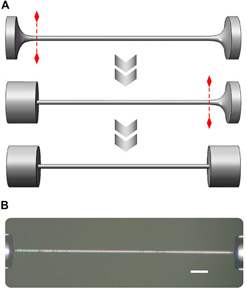
FIGURE 1. (A) Schematic of the fabrication process of the sensor. (B) Optical micrograph of the sensor. The white scale bar at the lower right corner is 50 μm.
3 Principle of microfiber optomechanical torsion sensor
Micromechanical resonators have extraordinary sensitivity, and have been applied to measure tiny force and mass changes by monitoring the resonant frequency shifts [46, 47]. As shown in Figure 1, the abrupt junctions between the microfiber and SMFs could confine resonant mechanical modes to the microfiber section, thereby enabling high mechanical quality factors Qm at low gas pressures. A large difference between the diameters of SMF and microfiber is beneficial to reduce the clamping loss and improve the Qm of the resonator. The resolution of sensor benefits from the Qm of the resonator. The resonant frequency fn of the nth mode of the microfiber resonator can be expressed as [48]:
where L and A are the length and cross-sectional area of the microfiber, E and I is the Young’s modulus and the moment of inertia, d is the diameter of the beam, ρ is the density, and σ is the axial tensile stress in the microfiber.
According to Eq. 1, the resonant frequency of the microfiber resonator could shift by adjusting the axial tensile stress. Figure 2 shows the theory model of the microfiber resonator with a torsion angle θ. The line AB changes to AC when a torsion angle θ is applied to the microfiber resonator, where the corresponding axial tensile stress σ from the torsion angle θ is [49]:
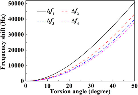
Combining Eqs 1, 2, the torsion angle θ could be demodulated by analyzing the resonant frequency shift of the microfiber resonator. Figure 3 shows that the theoretic frequency shifts ∆fn of different mechanical resonant modes as a function of torsion angle θ for a microfiber with a length of 950 μm and a diameter of 13 μm. The frequency shift of the fundamental mode is more than other higher modes, and the frequency shifts will decrease as the mode n increases. Therefore, it is more sensitive to choose the fundamental mode as a sensing quantity than other modes.
4 Experiment and discussion
The scheme of the experimental setup for characterizing the sensor is shown in Figure 4. The light from a continuous-wave laser with a wavelength of 1,550 nm (LSM-DFB-1550, OPEAK) is injected into the variable optical attenuator and the sensor by standard SMFs, where the lead-in SMF connects with the sensor by a fiber-optic adapter. The transmission light from the sensor is converted to the corresponding electrical signal by a fast photodetector (PDB440, Thorlabs). By demodulating the electrical signal from the photodetector with an electronic spectrum analyzer (ESA, RBW is 1 Hz), we can get the resonant frequency of the microfiber mechanical resonator and the torsion angle. The sensor is mounted onto a mechanical holder with a rotary stepper positioner (Attocube, ANR51/RES) and a piezoelectric stack (Green, PI, PD050.3x1). The piezoelectric stack is used to excite the microfiber mechanical resonator to monitoring the shift of the resonant frequency, because the thermal noise of the microfiber resonator is difficult to be identified directly in our experiments. It should be noted that it is possible to abandon the piezoelectric stack for the proposed sensing mechanism when the thermal noise of the microfiber resonator could be detected successfully. The sensor and holder are fixed in a vacuum chamber with a gas pressure of 5 × 10⁻⁷ mbar in our experiments.
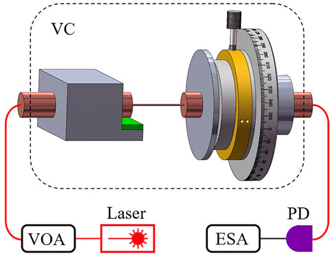
FIGURE 4. Schematic of the experimental setup, including a vacuum chamber (VC), variable optical attenuator (VOA), photodetector (PD), and electronic spectrum analyzer (ESA).
The measured normalized mechanical power spectrum of fundamental mode for the sensor with 950-μm length and 13-μm diameter is shown in Figure 5. The circular points and red solid line are the experimental data and fitted curve according to the response function of the mechanical resonator, respectively. Figure 5 shows that the resonant frequency of the fundamental mode is 64.102 kHz and the linewidth is 12 Hz. Therefore, the corresponding Qm of the mechanical resonator is 5,300. The inset is the mode shape of the resonant mode in Figure 5.
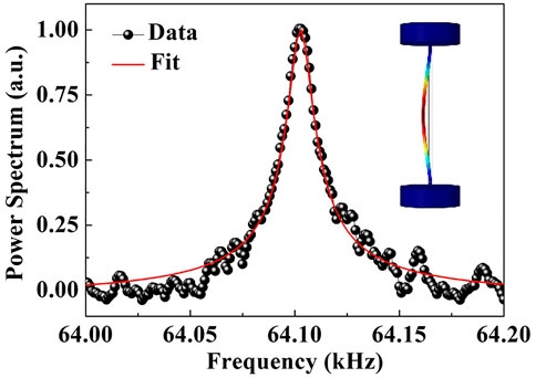
FIGURE 5. Normalized mechanical power spectrum of the fundamental mode for the sensor. Inset mode shape of the fundamental mode.
To demonstrate the torsion sensor, we tested the response of the sensor to the torsion by using the rotary stepper positioner at room temperature. Figure 6 shows the measured and calculated mechanical resonant frequency shifts of the sensor as a function of torsion angle from 0° to 50°. The black solid line represents the calculated curve according to the Eqs 1, 2. The red solid line and square symbols are the fitting curve and measured frequency shifts. As shown in Figure 6, when the torsion angle increases, the resonant frequency shifts to the large frequency. The change of the resonant frequency is 44.562 kHz over 50° change in the torsion angle. The resonant frequency shift is non-linearly proportional to the torsion angle, and becomes larger as the torsion angle increases. The difference between the calculated and measured curves is mainly due to the splicing spots between the SMF and the microfiber, where the properties of the splicing spots are different from the microfiber. When the power of arc discharge is lower than the optimal value, air bubbles appear in the splicing spots, which results in the decrement of the connection area A between the microfiber and the SMF. The corresponding shift of resonant frequency reduces according to Eqs 1, 2. In our experiments, the splicing spots of the sensors are easy to break when the torsion angle is larger than 50°. Therefore, the splicing technique between the SMF and microfiber needs to be further optimized to improve the measure range and sensitivity of the proposed sensor. According to the fitting curve of the measured data, the highest sensitivity of the sensor tested in our experiments is 1,687 Hz/degree, and the corresponding resolution of torsion angle is up to 0.0006°. To the best of our knowledge, the maximum of the resonant wavelength shifts for the reported fiber-optic torsion sensors is 320 pm/degree in Ref. [13], and the corresponding the resolution of torsion angle is 0.064° using an optical spectrum analyzer with a representative resolution of 20 pm. The resolution of torsion angle is improved about 2 orders of magnitude for the proposed sensor. Therefore, the proposed device can provide a real-time high-sensitive measurement of the torsion angle.
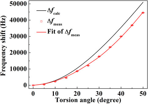
FIGURE 6. Measured and calculated mechanical resonant frequency shifts of the sensor as a function of torsion angle.
5 Conclusion
In conclusion, we have demonstrated a novel optomechanical torsion sensor based on a microfiber mechanical resonator. The torsion angle can be determined directly from a measure of the resonant frequency shift of the microfiber mechanical resonator. Experimental results show that the achieved highest sensitivity of the sensor with a 950-μm length and 13-μm diameter reaches 1,687 Hz/degree. The proposed torsion sensor has advantages of small size, light weight, multiplexing, remote measurement, and immunity to electromagnetic interference, and therefore could be used in some precision machinery equipment fields. For example, the torsion sensors for intelligent robots should be compact and light to avoid a major modification in kinematics and dynamics of robots. In addition, low torsional stiffness is beneficial to reduce the influence on the natural frequency of the robot arm. The proposed torsion sensor could also be embedded into mechanical shafts to monitor the torque loads and health condition of the shafts, and particularly suitable for applications in harsh environments.
Data availability statement
The original contributions presented in the study are included in the article/supplementary material, further inquiries can be directed to the corresponding authors.
Author contributions
Conceptualization, QZ and YL; methodology, JZ and SY; experiments, RZ and YX; writing—original draft preparation, QZ and YL All authors have read and agreed to the published version of the manuscript.
Funding
This work was supported by the funding from the National Natural Science Foundation of China (NSFC) (12174232, U21A6006, 11804208, and 11774209) and Shanxi 1331KS.
Conflict of interest
The authors declare that the research was conducted in the absence of any commercial or financial relationships that could be construed as a potential conflict of interest.
Publisher’s note
All claims expressed in this article are solely those of the authors and do not necessarily represent those of their affiliated organizations, or those of the publisher, the editors and the reviewers. Any product that may be evaluated in this article, or claim that may be made by its manufacturer, is not guaranteed or endorsed by the publisher.
References
1. Wang G, Pran K, Sagvolden G, Havsgard GB, Jensen AE, Johnson GA, et al. Ship hull structure monitoring using fibre optic sensors. Smart Mater Struct (2001) 10:472–8. doi:10.1088/0964-1726/10/3/308
2. Tsetserukou D, Tadakuma R, Kajimoto H, Tachi S. Optical torque sensors for implementation of local impedance control of the arm of humanoid robot. In: Proceedings of IEEE International Conference on Robotics and Automation; 15-19 May 2006; Orlando, Florida, USA (2006). p. 1674–1679. doi:10.1109/ROBOT.2006.1641947
3. Xu R, Yurkewich A, Patel R. Curvature, torsion, and force sensing in continuum robots using helically wrapped FBG sensors. IEEE Robot Autom Lett (2016) 1:1052–9. doi:10.1109/LRA.2016.2530867
4. McKenzie I, Ibrahim S, Haddad E, Abad S, Hurni A, Cheng LK. Fiber optic sensing in spacecraft engineering: An historical perspective from the European space agency. Front Phys (2021) 9:719441. doi:10.3389/fphy.2021.719441
5. Gong CY, Gong Y, Chen QS, Rao YJ, Peng GD, Fan XD. Reproducible fiber optofluidic laser for disposable and array applications. Lab Chip (2017) 17:3431–6. doi:10.1039/c7lc00708f
6. Rao YJ, Wang YP, Ran ZL, Zhu T. Novel fiber-optic sensors based on long-period fiber gratings written by high-frequency CO2 laser pulses. J Light Technol (2003) 21:1320–1327. doi:10.1109/JLT.2003.810561
7. Deng M, Xu JS, Zhang Z, Bai ZY, Liu S, Wang Y, et al. Long period fiber grating based on periodically screw-type distortions for torsion sensing. Opt Express (2017) 25:14308–14316. doi:10.1364/OE.25.014308
8. Chen X, Zhou K, Zhang L, Bennion I. In-fiber twist sensor based on a fiber Bragg grating with 81$^{\circ}$ tilted structure. IEEE Photon Technol Lett (2006) 18:2596–8. doi:10.1109/LPT.2006.887371
9. Huang B, Shu XW. Ultra-compact strain- and temperature insensitive torsion sensor based on a line-by-line inscribed phase-shifted FBG. Opt Express (2016) 24:17670–17679. doi:10.1364/OE.24.017670
10. Frazão O, Silva RM, Kobelke J, Schuster K. Temperature- and strain-independent torsion sensor using a fiber loop mirror based on suspended twin-core fiber. Opt Lett (2010) 35:2777–2779. doi:10.1364/OL.35.002777
11. Fu QJ, Zhang JD, Liang CC, Lkechukwu IP, Yin GL, Lu L, et al. Intensity-modulated directional torsion sensor based on in-line optical fiber Mach–Zehnder interferometer. Opt Lett (2018) 43:2414–2417. doi:10.1364/OL.43.002414
12. Song BB, Zhang H, Miao YP, Lin W, Wu JX, Liu HF, et al. Highly sensitive twist sensor employing Sagnac interferometer based on pm-elliptical core fibers. Opt Express (2015) 23:15372–15379. doi:10.1364/OE.23.015372
13. Wu JJ, Shen X, Luo X, Hu XW, Peng JG, Yang LY, et al. Temperature-insensitive torsion sensor with sensitivity-enhanced by processing a polarization-maintaining photonic crystal fiber. Opt Commun (2017) 401:80–4. doi:10.1016/j.optcom.2017.05.048
14. Song BB, Miao YP, Lin W, Zhang H, Wu JX, Liu B. Multi-mode interferometer-based twist sensor with low temperature sensitivity employing square coreless fibers. Opt Express (2013) 21:26806–26811. doi:10.1364/OE.21.026806
15. Zhou Q, Zhang WG, Chen L, Yan TY, Zhang LY, Wang L, et al. Fiber torsion sensor based on a twist taper in polarization-maintaining fiber. Opt Express (2015) 23:23877–23886. doi:10.1364/OE.23.023877
16. Aspelmeyer M, Kippenberg TJ, Marquardt F. Cavity optomechanics. Rev Mod Phys (2014) 86:1391–452. doi:10.1103/RevModPhys.86.1391
17. Li BB, Ou LF, Lei YC, Liu YC. Cavity optomechanical sensing. Nanophotonics (2021) 10:2799–832. doi:10.1515/nanoph-2021-0256
18. Hu YW, Xiao YF, Liu YC, Gong QH. Optomechanical sensing with on-chip microcavities. Front Phys (2013) 8:475–90. doi:10.1007/s11467-013-0384-y
19. Hoang TM, Ma Y, Ahn J, Bang J, Robicheaux F, Yin ZQ, et al. Torsional optomechanics of a levitated nonspherical nanoparticle. Phys Rev Lett (2016) 117:123604. doi:10.1103/PhysRevLett.117.123604
20. Chen WJ, Özdemir SK, Zhao GM, Wiersig J, Yang L. Exceptional points enhance sensing in an optical microcavity. Nature (2017) 548:192–6. doi:10.1038/nature23281
21. Jing H, Lü H, Özdemir SK, Carmon T, Nori F. Nanoparticle sensing with a spinning resonator. Optica (2018) 5:1424–1430. doi:10.1364/OPTICA.5.001424
22. Wan S, Niu R, Ren HL, Zou CL, Guo GC, Dong CH. Experimental demonstration of dissipative sensing in a self-interference microring resonator. Photon Res (2018) 6:681–685. doi:10.1364/PRJ.6.000681
23. Chen WJ, Zhang J, Peng B, Ozdemir SK, Fan XD, Yang L. Parity-time-symmetric whispering-gallery mode nanoparticle sensor [Invited]. Photon Res (2018) 6:A23–A30. doi:10.1364/PRJ.6.000A23
24. Chen XY, Li TC, Yin ZQ. Nonadiabatic dynamics and geometric phase of an ultrafast rotating electron spin. Sci Bull (2019) 64:380–4. doi:10.1016/j.scib.2019.02.018
25. Yang C, Wei XR, Sheng JT, Wu HB. Phonon heat transport in cavity-mediated optomechanical nanoresonators. Nat Commun (2020) 11:4656. doi:10.1038/s41467-020-18426-4
26. Wang JQ, Yang YH, Li M, Hu XX, Surya JB, Xu XB, et al. Efficient frequency conversion in a degenerate χ(2) microresonator. Phys Rev Lett (2021) 126:133601. doi:10.1103/PhysRevLett.126.133601
27. Zhang J, Peng B, Kim S, Monifi F, Jiang XF, Li YH, et al. Optomechanical dissipative solitons. Nature (2021) 600:75–80. doi:10.1038/s41586-021-04012-1
28. Forstner S, Prams S, Knittel J, van Ooijen ED, Swaim JD, Harris GI, et al. Cavity optomechanical magnetometer. Phys Rev Lett (2012) 108:120801. doi:10.1103/PhysRevLett.108.120801
29. Wu M, Wu NLY, Firdous T, Sani FF, Losby JE, Freeman MR, et al. Nanocavity optomechanical torque magnetometry and radiofrequency susceptometry. Nat Nanotechnol (2017) 12:127–31. doi:10.1038/NNANO.2016.226
30. Zhu JG, Zhao GM, Savukov I, Yang L. Polymer encapsulated microcavity optomechanical magnetometer. Sci Rep (2017) 7:8896. doi:10.1038/s41598-017-08875-1
31. Li BB, Bílek J, Hoff UB, Madsen LS, Forstner S, Prakash V, et al. Quantum enhanced optomechanical magnetometry. Optica (2018) 7:850–856. doi:10.1364/OPTICA.5.000850
32. Teufel JD, Donner T, Castellanos-Beltran MA, Harlow JW, Lehnert KW. Nanomechanical motion measured with an imprecision below that at the standard quantum limit. Nat Nanotechnol (2009) 4:820–3. doi:10.1038/NNANO.2009.343
33. Krause AG, Winger M, Blasius TD, Lin Q, Painter O. A high-resolution microchip optomechanical accelerometer. Nat Photon (2012) 6:768–72. doi:10.1038/NPHOTON.2012.245
34. Cervantes FG, Kumanchik L, Pratt J, Taylor JM. High sensitivity optomechanical reference accelerometer over 10 kHz. Appl Phys Lett (2014) 104:221111. doi:10.1063/1.4881936
35. Zhou F, Bao YL, Madugani R, Long DA, Gorman JJ, LeBrun TW. Broadband thermomechanically limited sensing with an optomechanical accelerometer. Optica (2021) 8:350–356. doi:10.1364/OPTICA.413117
36. Li JJ, Zhu KD. All-optical mass sensing with coupled mechanical resonator systems. Phys Rep (2013) 525:223–54. doi:10.1016/j.physrep.2012.11.003
37. Naik AK, Hanay MS, Hiebert WK, Feng XL, Roukes ML. Towards single-molecule nanomechanical mass spectrometry. Nat Nanotechnol (2009) 4:445–50. doi:10.1038/NNANO.2009.152
38. Yu WY, Jiang WC, Lin Q, Lu T. Cavity optomechanical spring sensing of single molecules. Nat Commun (2016) 7:12311. doi:10.1038/ncomms12311
39. Lin Q, He B, Xiao M. Mass sensing by detecting the quadrature of a coupled light field. Phys Rev Appl (2017) 96:043812. doi:10.1103/PhysRevA.96.043812
40. Basiri-Esfahani S, Armin A, Forstner S, Bowen WP. Precision ultrasound sensing on a chip. Nat Commun (2019) 10:132. doi:10.1038/s41467-018-08038-4
41. Pan JS, Zhang B, Liu ZY, Zhao X, Feng YH, Wan L, et al. Microbubble resonators combined with a digital optical frequency comb for high-precision air-coupled ultrasound detectors. Photon Res (2020) 8:303–310. doi:10.1364/PRJ.376640
42. Li H, Dong BQ, Zhang X, Shu X, Chen XF, Hai RH, et al. Disposable ultrasound-sensing chronic cranial window by soft nanoimprinting lithography. Nat Commun (2019) 10:4277. doi:10.1038/s41467-019-12178-6
43. Yang JF, Qin T, Zhang FX, Chen XF, Jiang XS, Wan WJ. Multiphysical sensing of light, sound and microwave in a microcavity Brillouin laser. Nanophotonics (2020) 9:2915–25. doi:10.1515/nanoph-2020-0176
44. Yu CQ, Niu R, Peng ZD, Li H, Luo YM, Zhou TJ, et al. A current sensor based on capillary microresonator filled with Terfenol-D nanoparticles. IEEE Photon Technol Lett (2021) 33:239–42. doi:10.1109/LPT.2021.3054629
45. Liao J, Yang L. Optical whispering gallery mode barcodes for high-precision and wide-range temperature measurements. Light Sci Appl (2021) 10:32. doi:10.1038/s41377-021-00472-2
46. Roy SK, Sauer VTK, Westwood-Bachman JN, Venkatasubramanian A, Hiebert WK. Improving mechanical sensor performance through larger damping. Science (2018) 360:eaar5220. doi:10.1126/science.aar5220
47. Pennetta R, Xie SR, Russell PS. Tapered glass-fiber microspike: High-Q flexural wave resonator and optically driven knudsen pump. Phys Rev Lett (2016) 117:273901. doi:10.1103/PhysRevLett.117.273901
48. Bokaian A. Natural frequencies of beams under tensile axial loads. J Sound Vib (1990) 142:481–98. doi:10.1016/0022-460X(90)90663-K
Keywords: optomechanics, torsion sensor, optical fiber, mechanical resonator, microfiber
Citation: Zhang Q, Zhang J, Yang S, Zhai R, Xie Y and Li Y (2023) Microfiber optomechanical torsion sensor. Front. Phys. 11:1147644. doi: 10.3389/fphy.2023.1147644
Received: 19 January 2023; Accepted: 13 April 2023;
Published: 21 April 2023.
Edited by:
Zhangqi Yin, Beijing Institute of Technology, ChinaReviewed by:
Hailang Dai, Shanghai Jiao Tong University, ChinaJin-hui Chen, Xiamen University, China
Copyright © 2023 Zhang, Zhang, Yang, Zhai, Xie and Li. This is an open-access article distributed under the terms of the Creative Commons Attribution License (CC BY). The use, distribution or reproduction in other forums is permitted, provided the original author(s) and the copyright owner(s) are credited and that the original publication in this journal is cited, in accordance with accepted academic practice. No use, distribution or reproduction is permitted which does not comply with these terms.
*Correspondence: Qiang Zhang, cXpoYW5nQHN4dS5lZHUuY24=; Yongmin Li, eW9uZ21pbkBzeHUuZWR1LmNu
 Qiang Zhang
 Jie Zhang1
 Shiwei Yang
