 Jie Wang
 Gang Ou1
 Zukun Lu
95% of researchers rate our articles as excellent or good
Learn more about the work of our research integrity team to safeguard the quality of each article we publish.
Find out more
ORIGINAL RESEARCH article
Front. Phys. , 02 February 2023
Sec. Interdisciplinary Physics
Volume 11 - 2023 | https://doi.org/10.3389/fphy.2023.1125431
This article is part of the Research Topic Advanced Signal Processing Techniques in Radiation Detection and Imaging View all 13 articles
This paper analyzes the performance of sample matrix inversion (SMI) filter used by antenna array receivers in pulse interference environment. Firstly, from the perspective of comparison, it is proved that the theoretical optimal signal to interference noise ratio (SINR) of SMI filter under pulse interference is the same with that under continuous interferences. Then the convergence characteristics of SMI filter under pulse interference are deduced, and the relationship between the convergence speed and length of training samples and duty of interferences is given. Finally, the results of signal simulation are consistent with those of numerical analysis, which verifies the correctness of theoretical analysis. The results show that the convergence speed of SMI filter decreases under pulse interference, and the SMI filter needs more training samples to suppress the pulse interference effectively.
Due to its excellent anti-jamming ability, antenna array receivers are widely used in satellite navigation, communication and other fields [1, 2]. It is clear that antenna array receivers have perfect interference suppression performance under continuous and stationary interferences [3, 4]. But the interferences faced by antenna array receivers are diverse and constantly occurring, and non-stationary and intermittent interferences are part of the threats [5–9]. Pulse interference is one type of intentional interferences from jammers [6, 10, 11]. As the input mutation caused by pulse interference destroys the steady state of the filter and even makes the filter hardly converge to the steady state [12], the pulse interference has a great impact on the anti-jamming processing based on recursive algorithm, such as recursive least-squares (RLS) algorithm. The focus is to catch the interference samples [13, 14] when the sample matrix inversion (SMI) algorithm was used for anti-jamming processing in antenna array receivers. Even if the interference samples are caught, the convergence characteristics of the SMI filter in the pulse interference environment need to be further analyzed. And analyzing the loss of theoretical optimal SINR is also necessary when studying the impact of pulse interference on SMI filter. The convergence characteristics of SMI filter in stationary environment were first given by Reed [15]. It is proved that in order to make the expected loss of SINR less than 3 dB, the length of training samples should be greater than 2D − 3, where D is the degree of freedom (DOF) of the filter. The conlusion was widely verified [16]. Some literature have also proved that the convergence speed of SMI filter based on eigenanalysis can be faster under stationary environment [17–19]. In order to solve the problem of slow convergence speed of SMI and poor anti-jamming performance with fewer samples, diagonal loading sample matrix inversion (LSMI) filter was suggested to improve the convergence speed of the filter [20, 21]. The convergence characteristics of LSMI have been analyzed and demonstrated in theory [22]. Tang [23] studied the convergence characteristics of LSMI filter in the amplitude heterogeneous clutter environment, which assumes that the amplitude of training signal is proportional to that of signal under test. At present, there is no research report on the convergence characteristics of SMI filter under pulse interferences.
The main contributions of this paper include: it is proved that the theoretical optimal SINR of SMI filter under pulse interferences is same with that under continuous interferences. The distribution function of SINR loss of SMI filter under pulse interferences is derived, and the expression of expected SINR loss with different number of samples and the duty of interferences is given. The numerical analysis and signal simulation with typical parameters are given, and their results are consistent. The conclusion of this paper shows that the performance of SMI filter may still deteriorate even the length of training samples is greater than the pulse period and 2D − 3.
We assume that the pulse interference is extracted from a wideband continuous signal with rectangular pulse. The time domain waveform is described as
where c(t) is the baseband signal, f0 is the carrier frequency which is the same with the interest signal, p(t) is a square wave with the expression as
where A represents the amplitude of the rectangular pulse, here we set A as 1. τ is the pulse width, and Ts is the pulse period.
The spectrum of pulse interference is
where Jc(f) is the spectrum of the continuous signal jc(t),
Since the low-pass filter exist before analog-to-digital conversion, the bandwidth of the interference entering the space-time filter is limited.
Taking the array satellite navigation receiver as an example, in the signal process flow, the antenna array receivers based on digital signal processing add the array anti-jamming processing segment compared with the single antenna receivers as shown in Figure 1. The signal process of the satellite navigation antenna array receivers mainly includes RF front-end, AD conversion, anti-jamming filter, channel process and other segments. Pulse interferences will have a certain impact on all the above segments. In the paper [11], the impact of pulse interferences on the baseband processing was analyzed. This paper mainly focuses on the impact of pulse interference on anti-jamming processing.
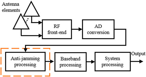
FIGURE 1. Signal processing flow of antenna array receiver.
The filter based on SMI use different optimization criteria to solve the filter weight vector. For example, minimum variance distortionless response (MVDR) filter solves the weight vector by minimizing the output power and constraining the satellite signal gain to 1, and the optimal weigth vector is
where as is the steer vector of the interest signal, which is calculated from the incident angle of the signal θ0 and the layout of the array. Ry is the covariance matrix of noise and interference, which can not be obtained accurately. Because the satellite signal power is much small than noise power, it is assumed that the sampled signal is the noise and interference signal, which means that
where σ2 is the noise power, Rj represents the covariance matrix of the interference signal. Under the assumption that the input signals are stationary, the covariance matrix of the samples is used to replace the real covariance matrix in the processing.
The performance is analyzed by taking the ratio of output SINR of space-time filter under continuous interference and pulse interference as the metric. Rc and Rp are the theoretical covariance matrices under continuous interference and pulse interference respectively. When the signal power is 1, after anti-jamming processing based on MVDR method, the optimal SNR of filter output in two cases are
where vθ is the steer vector of interference. ⊗ denotes the Kronecker product [25]. Rf is time domain covariance matrix of interference, whose eigenvalues and corresponding eigenvectors are λi, vfi (i = 1, ⋯M). So the larger eigenvalues of Rj are λi (i = 1, ⋯M) and the corresponding eigenvectors are vi = vθ ⊗vfi. To simplify the analysis, we assume that the time-domain covariance matrix of the interest signal has only one non-zero eigenvalue and the corresponding eigenvector is af, the space-time steer vector of the navigation signal is as = aθ ⊗af, aθ is the spatial steer vector of the interest signal. Then the optimal output SINR of the filter is
The above expression shows that the angle between steer vectors of interest signal and interference affects the theoretical optimal SINR. When the incident direction of interference and interest signal are not in the same main lobe, the differences of frequency domain characteristics of interference can be ignored. Therefore, under pulse interference and continuous interference, the ratio of theoretical optimal output SINR of the SMI filter is close to 1, and the loss of theoretical optimal SINR caused by pulse interference is 0 dB.
With the analysis of last section, it is obvious that if the covariance matrix of the interference is accurately estimated, performances of SMI filter under pulse interference and continuous interference are the same. Next, the convergence characteristics of SMI filter under pulse interference are derived. Assuming that one or more pulse cycles are in training samples, and total interest signal power of the SMI filter output is
where, K is the length of the training samples, ts is the sampling interval, vs = as is the steer vector of the interest signal, and
Assuming that the pulse duty is β, the average output SINR of all the L data cells is
The covariance matrix in a sampling period is approximate as
where
Next, the theoretical distribution of ρ under different training samples number and pulse interference parameters is analyzed. Let
and Eq. 12 can be written as
Decomposing R1 and R2 into
Assuming that the pulse interference power is much greater than the noise power and β is not too small, which means that
Let
According to the derivation of Ref. [23], the distribution of ρ is as follows
where
When Kβ ≥ rc, the expression of average SINR loss is
In the above derivation, the first assumption, i.e.,
The above derivation shows that, the convergence rate is consistent with that of LSMI filter under the amplitude heterogeneous clutter environment when taking the length of interference samples as the reference variable. Combined with the implementation process of the SMI filter, the conclusion can be explained as follow. If the sampling length is long enough, the estimation of the covariance matrix of the noise signal can be approximately accurate. At this time, it can be considered that the unit matrix with amplitude
In the numerical simulation, we set the DOF of the filter as D = 36, and set training samples length K = 10D = 360 and K = 5D = 180 as two cases. Figure 2 shows the change of the expected value of SINR loss with β(Kβ ≥ rc) when the DOF rc of the interference subspace are 18 and 27 respectively. The results show that even if K is greater than 2D, it causes a large loss of SINR. Only a larger value of K can reduce the loss of SINR.
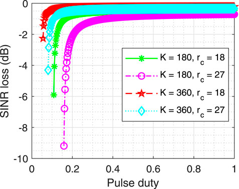
FIGURE 2. The curve of loss of SINR with different β.
Taking the 4-elements central circular array satellite navigation receiver as the simulation object, SMI space-time filtering is used [26]. The diagram of the simulation is shown in Figure 3. The number of time-taps is 9, so the DOF of the filter is 36. The interference signal is a limited bandwidth random noise, and its bandwidth is 20 MHz. Two and three interferences are set respectively, so the DOF of the interference subspace are 18 and 27. The SNR is −28 dB, the INR is 92 dB, the navigation signal is BPSK modulation and the spread spectrum code rate is 10.23 MHz. The central frequency of all signals is 1,268.42 MHz. The sampling rate is set as fc = 40.96MHz, so sampling interval
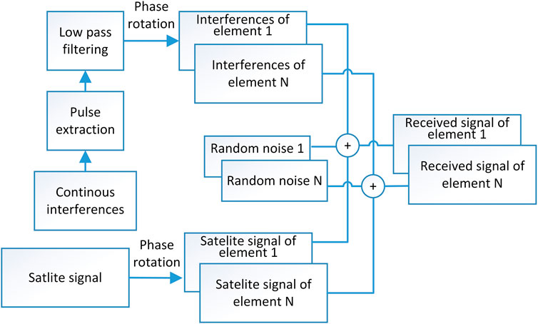
FIGURE 3. Block diagram of array signals simulation in pulse interference environment.
In the first case, we set the training samples length of SMI filter as 360 and 40,960 respectively, and take the output SINR with 40,960 training samples as the reference optimal SINR. For all the SMI filter tested, the training data cell is followed by the test cell. The output SINR of every test has been averaged over 5 m. After 20 times Monte Carlo simulations, the average SINR loss under pulse interferences with pulse period equal to 360tc and pulse duty changing from
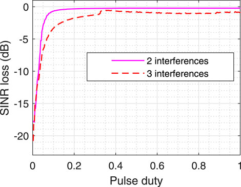
FIGURE 4. Average SINR loss of Monte Carlo simulations (K = 360).
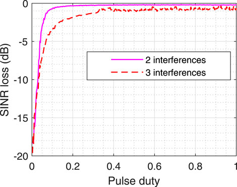
FIGURE 5. SINR loss of one-time simulation (K = 360).
According to Figure 4 and Figure 5, it can be seen that the curve trend of one-time simulation results is basically consistent with that of Monte Carlo simulation results, and the trend of SINR loss curve obtained by simulation is consistent with that of theoretical curve (Kβ ≥ rc). When Kβ < rc the loss of SINR is large. For another case, we set the length of training samples to 720 and pulse interference period to 360tc. Figure 6 shows the loss of SINR under different duty cycles under this case. It shows that under the same conditions, the length of training samples increases and the loss of SINR decreases.
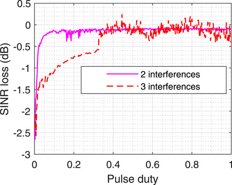
FIGURE 6. SINR loss of one-time simulation (K = 720).
Figure 7 shows the whole signals power output by the filter when the pulse period of two interferences is 360tc and the pulse duty is
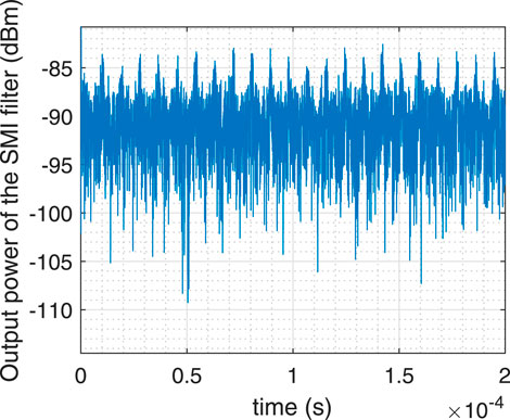
FIGURE 7. Output power of the SMI filter.
This paper studies the performance of SMI filter under pulse interference. It is proved that the output SINR of SMI filter under impulse interference is consistent with that under continuous interference when the covariance matrix of interference signal is accurately estimated. At the same time, the convergence rate of SMI filter under impulse interference is studied, and the expression of convergence rate is given. Finally, the above conclusions are verified by signal simulation. The conclusion shows that SMI filter needs longer training sample length under pulse interference, which provides a useful guideline for SMI filter design in pulse interference environment in satellite navigation, communication and other fields.
The original contributions presented in the study are included in the article/Supplementary Material, further inquiries can be directed to the corresponding author.
JW: Conceptualization; Methodology; Writing—original draft. WL: Project administration. GO: Supervision. ZL: Investigation. HY: Writing—review and editing.
This work was supported by the National Natural Science Foundation of China (62003354).
The authors declare that the research was conducted in the absence of any commercial or financial relationships that could be construed as a potential conflict of interest.
All claims expressed in this article are solely those of the authors and do not necessarily represent those of their affiliated organizations, or those of the publisher, the editors and the reviewers. Any product that may be evaluated in this article, or claim that may be made by its manufacturer, is not guaranteed or endorsed by the publisher.
1. Fante RL, Vacarro JJ. Cancellation of jammers and jammer multipath in a gps receiver. IEEE Aerospace Electron Syst Mag (1998) 13:25–8. doi:10.1109/62.730617
2. Wu R, Dong J, Wang M. Wearable polarization conversion metasurface mimo antenna for biomedical applications in 5 ghz wban. Biosensors (2023) 13:73. doi:10.3390/bios13010073
3. Fante RL, Vaccaro JJ. Wideband cancellation of interference in a gps receive array. IEEE Trans Aerospace Electron Syst (2000) 36:549–64. doi:10.1109/7.845241
4. Brown A. Performance and jamming test results of a digital beamforming GPS receiver. In: Tech. rep. Colorado Springs, CO, USA: NAVSYS CORP COLORADO SPRINGS CO (2002).
5. Pattinson M, Dumville M, Ying Y, Fryganiotis D, Bhuiyan M, Thombre S, et al. Standardisation of gnss threat reporting and receiver testing through international knowledge exchange, experimentation and exploitation [strike3]. Eur J Navig (2017) 15:4–8.
6. Thombre S, Bhuiyan MZH, Eliardsson P, Gabrielsson B, Pattinson M, Dumville M, et al. Gnss threat monitoring and reporting: Past, present, and a proposed future. The J Navigation (2018) 71:513–29. doi:10.1017/s0373463317000911
7. Bhuiyan MZ, Ferrara NG, Thombre S, Hashemi A, Pattinson M, Dumville M, et al. H2020 strike3: Standardization of interference threat monitoring and receiver testing-significant achievements and impact. In: 2019 European Microwave Conference in Central Europe (EuMCE). Prague, Czech Republic: IEEE (2019). p. 311–4.
8. Li B, Qiao J, Lu Z, Yu X, Song J, Lin B, et al. Influence of sweep interference on satellite navigation time-domain anti-jamming. Front Phys (2023) 10. doi:10.3389/fphy.2022.1063474
9. Pan Y, Dong J. Design and optimization of an ultrathin and broadband polarization-insensitive fractal fss using the improved bacteria foraging optimization algorithm and curve fitting. Nanomaterials (2023) 13:191. doi:10.3390/nano13010191
10. Jie W, Wenxiang L, Feiqiang C, Zukun L, Gang O. Gnss array receiver faced with overloaded interferences: Anti-jamming performance and the incident directions of interferences. J Syst Eng Electron (2022) 2022:1–7. doi:10.23919/jsee.2022.000072
11. Wang J, Liu W, Ou G, Xiao W, Wang H, Dong T. Channel scintillations of array global navigation satellite system receiver under distributed intermittent interferences. IET Radar, Sonar and Navigation (2022). doi:10.1049/rsn2.12335
12. Park DJ, Jun BE, Kim JH. Fast tracking rls algorithm using novel variable forgetting factor with unity zone. Electron Lett (1991) 27:2150–1. doi:10.1049/el:19911331
13. Siddiqui FA, Sreng V, Danilo-Lemoine F, Falconer D. Suppression of intermittent interference using smart antenna with distributed training scheme. In: Proceedings of 2014 11th International Bhurban Conference on Applied Sciences and Technology (IBCAST). 14th-18th January, 2014. Islamabad, Pakistan: IEEE (2014). p. 425–9. doi:10.1109/IBCAST.2014.6778181
14. Cai X, Huang Z, Li B. Asynchronous and non-stationary interference cancellation in multiuser interference channels. IEEE Trans Wireless Commun (2021) 20:4976–89. doi:10.1109/twc.2021.3064048
15. Reed IS, Mallett JD, Brennan LE. Rapid convergence rate in adaptive arrays. IEEE Trans Aerospace Electron Syst (1974) AES-10:853–63. doi:10.1109/taes.1974.307893
16. Liu J, Liu W, Liu H. A simpler proof of rapid convergence rate in adaptive arrays. IEEE Trans Aerospace Electron Syst (2017) 53:135–6. doi:10.1109/taes.2017.2649678
17. Haimovich AM, Bar-Ness Y. An eigenanalysis interference canceler. IEEE Trans signal Process (1991) 39:76–84. doi:10.1109/78.80767
18. Steiner M, Gerlach K. Fast-converging maximum-likelihood interference cancellation. In: Proceedings of the 1998 IEEE Radar Conference, RADARCON’98. Challenges in Radar Systems and Solutions (Cat. No. 98CH36197). Dallas, TX, USA: IEEE (1998). p. 117–22. doi:10.1109/NRC.1998.677987
19. Gierull C. Statistical analysis of the eigenvector projection method for adaptive spatial filtering of interference. IEE Proceedings-Radar, Sonar and Navigation (1997) 144:57–63. doi:10.1049/ip-rsn:19971075
20. Carlson BD. Covariance matrix estimation errors and diagonal loading in adaptive arrays. IEEE Trans Aerospace Electron Syst (1988) 24:397–401. doi:10.1109/7.7181
21. Gabriel W. Using spectral estimation techniques in adaptive processing antenna systems. IEEE Trans antennas propagation (1986) 34:291–300. doi:10.1109/tap.1986.1143827
22. Gierull CH. Performance analysis of fast projections of the hung-turner type for adaptive beamforming. Signal Process. (1996) 50:17–28. doi:10.1016/0165-1684(96)00007-2
23. Tang B, Tang J, Peng Y. Convergence rate of lsmi in amplitude heterogeneous clutter environment. IEEE Signal Process. Lett (2010) 17:481–4. doi:10.1109/lsp.2010.2044849
24. Guerci J, Bergin J. Principal components, covariance matrix tapers, and the subspace leakage problem. IEEE Trans Aerospace Electron Syst (2002) 38:152–62. doi:10.1109/7.993236
Keywords: sample matrix inversion, pulse interference, convergence rate, antenna array, training samples
Citation: Wang J, Ou G, Liu W, Lu Z and Yin H (2023) Performance analysis of SMI filter for antenna array receiver in pulse interference environment. Front. Phys. 11:1125431. doi: 10.3389/fphy.2023.1125431
Received: 16 December 2022; Accepted: 20 January 2023;
Published: 02 February 2023.
Edited by:
Jian Dong, Central South University, ChinaReviewed by:
Yayun Cheng, Harbin Institute of Technology, ChinaCopyright © 2023 Wang, Ou, Liu, Lu and Yin. This is an open-access article distributed under the terms of the Creative Commons Attribution License (CC BY). The use, distribution or reproduction in other forums is permitted, provided the original author(s) and the copyright owner(s) are credited and that the original publication in this journal is cited, in accordance with accepted academic practice. No use, distribution or reproduction is permitted which does not comply with these terms.
*Correspondence: Wenxiang Liu, bGl1d2VueGlhbmcwOEBudWR0LmVkdS5jbg==
Disclaimer: All claims expressed in this article are solely those of the authors and do not necessarily represent those of their affiliated organizations, or those of the publisher, the editors and the reviewers. Any product that may be evaluated in this article or claim that may be made by its manufacturer is not guaranteed or endorsed by the publisher.
Research integrity at Frontiers
Learn more about the work of our research integrity team to safeguard the quality of each article we publish.