- Wuhan National Laboratory for Optoelectronics (WNLO), Huazhong University of Science and Technology, Wuhan, Hubei, China
We presented an experimental comparison of the core-composition difference on the suppression of the photodarkening and transverse mode instability effects. Two core-composition fibers, entailing Yb/Al/Ce and Yb/Al/P co-doped fibers, were fabricated by MCVD process combined with solution doping technique. The parameters of two fibers were almost the same. The PD-induced loss at equilibrium was 3.94 dB/m at 702 nm in Yb/Al/Ce fiber, while it was 0.99 dB/m in Yb/Al/P fiber. To obtain a deeper understanding of the impact of PD on laser performance, a bidirectional pumping fiber amplifier was constructed. Compared with Yb/Al/Ce co-doped fiber, the TMI thresholds of Yb/Al/P co-doped fiber were enhanced in co-pumped and counter-pumped schemes. Meanwhile, the slope efficiency in bidirectional scheme was promoted by 4%. Moreover, the transmittance at 638 nm confirmed the superior PD resistance of Yb/Al/P co-doped fiber. These experimental results pave the way for the further development of high-power fiber lasers.
1 Introduction
High power fiber lasers (HPFLs), attributed to their considerable advantages of excellent beam quality, high conversion efficiency, efficient heat dissipation, and compact structure [1–3], have been broadly utilized in industrial processing, military defense, medical treatment and other fields [4, 5]. With the development of the double-clad fibers, high-power laser diodes (LDs) and passive devices, the output powers of fiber lasers and amplifiers have been unprecedentedly promoted, exceeding 20 kW [6]. However, the remarkable evolutions of continuous-wave broadband fiber lasers and amplifiers are hindered by non-linear effects (NLEs), such as stimulated Raman scattering (SRS) [7–10]. In recent years, the threshold-like onset of transverse mode instability (TMI) is the main limitation for the further power scaling in the fiber laser systems [11–20].
It is well known that HPFLs are impressionable for the photodarkening (PD) effect, which might weaken the long-term stability of fiber lasers [21]. PD effect, by producing color centers, can lead to broadband absorption from the ultraviolet to the near infrared, inducing the significant decline of signal laser output power [22]. Additionally, the absorption range of color centers contains the absorption and emission band of Yb-doped fibers, which will absorb both pump light and signal light and generate a large amount of thermal load [23].
Further, PD-induced thermal load will result in a series of issues. By theoretically calculating the thermally-induced mode loss evolution, it showed that the refractive index of the Yb-doped fiber would be changed by the thermo-optic effect, which affected the waveguide structure and altered the bending loss of different modes [24]. Moreover, the phase of the beam could be distorted by PD-induced thermal load [25]. Meanwhile, PD effect would significantly increase the thermal load of the active fiber and aggravate thermally induced refractive index grating, which eventually triggered the occurrence of TMI effect [26]. It was also expected that even a slight reduction of the PD-induced loss would cause the significant increment of the TMI threshold. Furthermore, researchers theoretically demonstrated that the PD effect might bring about the quasi-static mode degradation on a time scale of minutes to hours [27]. They considered that the energy of the fundamental mode (FM) unidirectionally transferred to high order mode (HOM), which caused by a phase-shifted refractive index grating. One year later, the PD-induced mode degradation was experimentally observed [28]. After 532 nm photobleaching, the beam profile recovered to Gaussian-shape profile, which agreed with the theory of quasi-static mode degradation.
Up to now, there are many strategies to mitigate the PD effect. Firstly, efficient structural design of the active fiber was beneficial to the mitigation of the PD effect. In 2009, a novel reduced mode overlap fiber design was proposed and demonstrated, which could reduce the mode overlap and thus decrease the PD loss [29]. And after 1,500 h operation, less than 7% slope efficiency degradation was found and further 500 h operation showed no degradation. Then, photobleaching and thermal bleaching were also commonly used in bleaching the existing PD loss [22, 30, 31]. They significantly bleached the photo-darkened fiber and mitigated the PD effect of the active fiber. Additionally, the PD effect would be restrained by H2 or O2 loading [32–34]. Afterwards, our previous work revealed that there was no PD loss in the H2-loaded fiber, while it was 114.4 dB/m at 702 nm in the pristine fiber [35]. Meanwhile, in the H2-loaded fiber, the output power remained stable and no TMI was observed, while the TMI effect in the pristine fiber occurred at a lower power level. Finally, by optimizing the co-doped composition including Ce, P, Al, and Na ions, it could effectively inhibit the PD effect [36–38]. It has been demonstrated that Yb/Ce co-doped and Yb/Al/P co-doped fibers were conducive to suppress the PD effect in HPFLs [39–41]. However, there are still lack of the impacts of the PD differences of co-doped Ce and P ions on the high-power laser performances, especially in the TMI effect.
In this contribution, the experimental comparisons of the core-composition difference were carried out. The parameters of Yb/Al/Ce and Yb/Al/P co-doped fibers fabricated by MCVD process were almost the same. Then, the PD-induced excess loss, laser performance, and the transmittance at 638 nm were successively measured. The PD-induced excess loss of Yb/Al/Ce and Yb/Al/P co-doped fibers were 3.94 dB/m and 0.99 dB/m at 702 nm. The TMI thresholds of Yb/Al/Ce and Yb/Al/P fibers in co-pumped amplifier were 1,803 W and 1,934 W, while they were 2434 W and 3314 W in counter-pumped amplifier, respectively. Meanwhile, compared with Yb/Al/Ce fiber, the slope efficiency of Yb/Al/P fiber in bidirectional scheme was promoted by 4%. Moreover, the 638 nm transmittance of Yb/Al/P co-doped fiber was superior than that of Yb/Al/Ce co-doped fiber.
2 Fiber fabrication and characterization
The Yb-doped fiber preform fabrication by modified chemical vapor deposition (MCVD) combined with solution doping technique (SDT) could be composed of the following steps [42]: deposition and pre-sintering of soot layers, solution soaking, dehydration, vitrification and collapsing into preforms. Generally speaking, the uniform preform profile could be realized by controlling the dopants incorporation such as soot porosity, soot oxidation temperature, solution doping condition [43] and collapse pressure.
The refractive index profiles (RIPs) of the fabricated preform were measured by PK104 (PHOTO KINETICS), as depicted in Figure 1. The RIPs of Yb/Al/Ce co-doped and Yb/Al/P co-doped preforms, which were measured at the positions of 100 mm and 200 mm along the longitudinal direction, were almost coincidental, manifesting excellent uniformity. Compared with Yb/Al/Ce preform, there was central RIP dip in the core of Yb/Al/P preform. It was because that the sublimation of P2O5 would take away part of the doped Yb2O3 and Al2O3 during MCVD process [44]. Additionally, compared with Yb/Al/Ce co-doped preform, more soot layers are deposited in Yb/Al/P co-doped preform and the deposition temperature was different. Thus, it would present that the RIP of Yb/Al/P co-doped preform was more fluctuant. From the Figures 1A, B, the core NAs of Yb/Al/Ce and Yb/Al/P preforms were 0.061 and 0.06, respectively, almost the same.
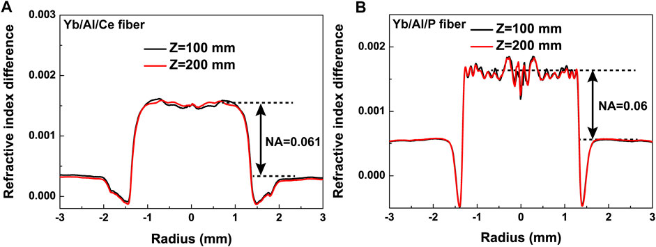
FIGURE 1. Refractive index profiles of (A) Yb/Al/Ce co-doped and (B) Yb/Al/P co-doped preforms at the positions of 100 mm and 200 mm along the longitudinal direction.
Subsequently, the above-mentioned fabricated preforms would be milled into an octagonal shape, and drawn and coated to form the double-cladding Yb-doped fiber on the drawing tower. As exhibited in Figure 2, The concentration distributions of the doped elements of two fibers across the core region were characterized by electron probe microanalysis (EPMA). For the Yb/Al/Ce co-doped fiber, as described in Figure 2A, the concentrations of Yb3+, Ce3+, Al3+, and F− were measured to be ∼0.75 wt%, ∼0.25 wt%, ∼0.3 wt%, and ∼0.1 wt%, respectively. For the Yb/Al/P co-doped fiber, as shown in Figure 2B, the concentrations of Yb3+, P5+, Al3+, and F− were measured to be ∼1.1 wt%, ∼1.4 wt%, ∼0.9 wt%, and ∼0.05 wt%, respectively. The insets in Figure 2 were the microscope images of the cross sections of two fibers, respectively. The pump absorption coefficients of Yb/Al/Ce and Yb/Al/P fibers were measured to be 1.214 dB/m and 1.217 dB/m at 976 nm, respectively. For meeting the sufficient absorption, the utilized fiber lengths of two fibers were both 20 m. Notably, the Yb3+ ions concentration of Yb/Al/P fiber was higher than that of Yb/Al/Ce fiber. This was because that the Yb-doped fiber core with Al3+ and P5+ would alter the effective cross-sections of the fiber, which reduced the absorption of pump power [41]. Thus, it was necessary to improve a higher Yb3+ ion concentration to reach a certain desired pump absorption. By several exploration, Yb/Al/Ce and Yb/Al/P co-doped fibers were successfully fabricated with almost the same pump absorption, as shown in the above results. In addition, the detailed parameters of two fibers were presented in Table 1.
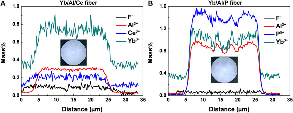
FIGURE 2. The elemental distribution of (A) Yb/Al/Ce co-doped and (B) Yb/Al/P co-doped fibers measured by electron probe microanalysis. (Insets: the microscope images of the cross sections of two fibers).
For purpose of a proper bending condition, bending losses at different bend radiuses were calculated using the finite element method with perfectly matched layer. In order to achieve the effective single-mode operation, the bending loss of the FM was less than 0.1 dB/m and the bending loss of the HOMs was more than 1 dB/m [45, 46]. Here, the values of core NA, core diameter, and center wavelength were set to be 0.06, 20 μm, and 1,080 nm, respectively. Thus, the normalized frequency V parameter was easily calculated to be 3.49, which indicated that there were only two transverse modes, LP01 and LP11, supported in the fiber core. The calculated results of the bend losses and the effective mode areas (EMAs) as functions of the bend radiuses were illustrated in Figures 3A, B, respectively. It was obvious that, as the increment of the bend radius, the bend losses of the transverse modes gradually decreased, while the EMAs gradually increased. From the results of Figure 3A, for the theoretical implementation of the single-mode operation, we considered that the proper bend radius region was between 4.5 cm and 8 cm and the corresponding EMA was between 256 μm2 and 264 μm2. Hereon, the bend radius of 5 cm was selected and corresponding LP01 loss, LP11 loss, and EMA were 0.03 dB/m, 36 dB/m, and 259 μm2, respectively, so as to achieve the better laser performances in the laser test.
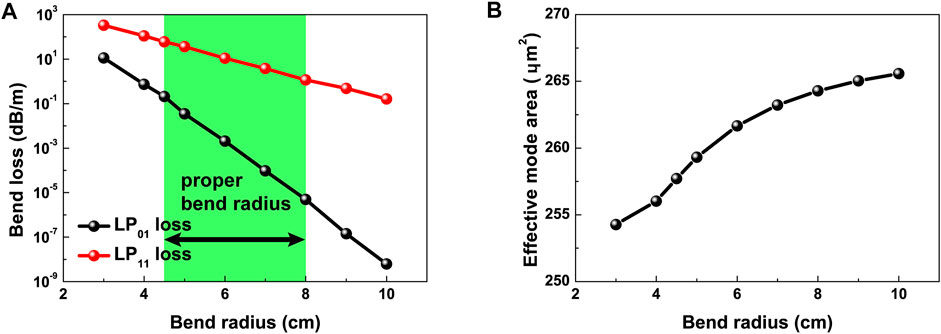
FIGURE 3. (A) The bend losses and (B) the effective mode areas as the functions of the different bend radiuses. Simulation parameters: core/inner cladding diameter of 20/400 μm, NA of 0.06 and center wavelength of 1,080 nm.
3 Experimental setup
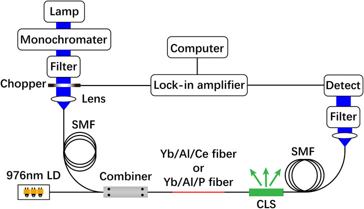
The experimental setup for PD-induced excess loss measurement was illustrated in Figure 4. The signal light source was a halogen lamp ranging from 600 to 1,650 nm and was free spaced into a single mode fiber (SMF). Three 976 nm wavelength-locked laser diodes (LDs) could achieve 160 W pump power output, which could provide 46% population inversion. The broadband signal light from SMF and pump light from 976 nm LDs were both injected into the Yb-doped fiber through a combiner. The length of the tested fiber was kept about 15 cm to maintain uniform inversion level. The cladding light would be stripped by cladding light stripper (CLS) between the Yb-doped fiber and SMF. To avoid heat accumulation, two air-cooling fans were employed to cool the LDs, Yb-doped fibers and CLS in the whole experiment. The absorption spectra of two Yb-doped fibers were recorded every 5 min.
For the measurement of laser performance, an all-fiberized bidirectional-pumped master oscillator power amplifier (MOPA) was constructed, as depicted in Figure 5. First of all, the master oscillator (MO) constituted by a pair of gratings and an active fiber was pumped by three 915-nm LDs from JDSU with each maximum pump power of 130 W. The high reflectivity fiber Bragg grating (HR-FBG) and the output coupler fiber Bragg grating (OC-FBG) fabricated by Teraxion could provide the reflectivity of 99.950% and 11.252%, the core NA of ∼0.07, the center wavelength of ∼1,080 nm, the core and inner cladding diameter of 14 μm and 250 μm, and the 3 dB bandwidth of 2.962 nm and 1.022 nm, respectively. The homemade 14/250 Yb-doped fiber was employed with the core NA of ∼0.07 and the fiber length of 21 m. After stripped by CLS, the pure seed light in the fiber core was obtained, with the center wavelength of ∼1,080 nm and the beam quality M2 factor of ∼1.2. Finally, a mode field adaptor (MFA) was used to match the signal fiber of the forward combiner, which possessed the core/cladding diameter of 14/250 μm on one end and 20/250 μm on the other.

FIGURE 5. Schematic diagram of the experimental setup for laser performance measurement. LD, laser diode; PC, pump combiner; HR-FBG, high reflectivity fiber Bragg grating; OC-FBG, output coupler fiber Bragg grating; CLS, cladding light stripper; MFA, mode field adaptor; F- and B-PSC, forward- and backward-pump and signal combiner; PD, photodetector; QBH, quartz block holder; CM, collimating mirror; BS, beam splitter; DM, dichroic mirror; NDF, neutral density filter; BSQ, beam squared.
Then, the seed light from the MO and the pump light from the forward/backward 976 nm LDs were poured into the power amplifier (PA). The forward pump and signal combiner (F-PSC) and the backward pump and signal combiner (B-PSC) were employed to permit the passage of the pump and signal lasers. Herein, the pigtails of the commercial F-PSC and B-PSC were passive fibers manufactured by Nufern and their core NAs were both about 0.06. The above-mentioned Yb/Al/Ce and Yb/Al/P fibers with the same length of 20 m were coiled in a racetrack-typed water-cooled plate with minimum and maximum bending diameter of 10 cm and 22 cm, respectively. The amplified signal laser propagated through CLS to strip the cladding light, which was received by a InGaAs photodetector to collect the time-domain signal and monitor the TMI process. Finally, the signal laser was exported through the quartz block holder (QBH).
As for the measurement of laser performance, the diverging signal laser output from QBH was collimated by a collimating mirror with the focal length of 150 mm, and then, the collimated laser was split by a high-reflectivity beam splitter (BS) with the reflectivity of >99%. A dichroic mirror (DM) was utilized to further eliminate the residual pump light, and subsequently, the purer laser was attenuated by a set of neutral density filter (NDF). The beam quality evolution was recorded by the Beam Squared (BSQ) and the optical spectra of the output laser was also measured with an optical spectrum analyzer (OSA).
4 Results and discussion
4.1 Photo-darkening excess losses of Yb/Al/Ce and Yb/Al/P fibers
Several absorption spectra of two Yb-doped fibers were obtained by PD loss measurement. Based on our previous investigation [35], the PD-induced excess losses at 633 nm, 702 nm, 810 nm, and 1,041 nm were selected to characterize the PD properties. Meanwhile, the data were also fitted by the classical stretched exponential function used in [47]. Additionally, the excess loss at 633 nm was commonly used in the characterization of PD properties. However, 633 nm was at the edge of the detection range of our measurement, and the data fluctuates greatly. Thus, for accuracy, 702 nm was chosen for comparison in this work.
The PD-induced excess losses of Yb/Al/Ce co-doped and Yb/Al/P co-doped fibers were depicted in Figures 6A, B. Overall, the excess losses of Yb/Al/Ce co-doped fiber at chosen wavelengths were more than twice as much as those of Yb/Al/P co-doped fiber. Concretely, by stretched exponential function fitting, the PD-induced equilibrium excess losses of Yb/Al/Ce co-doped fiber at 633 nm, 702 nm, 810 nm, and 1,041 nm were calculated to be 6.73 dB/m, 3.94 dB/m, 1.37 dB/m, and 0.58 dB/m, respectively. For Yb/Al/P co-doped fiber, the excess losses at 810 nm and 1,041 nm were nearly 0 and only the excess losses of 633 nm and 702 nm were fitted. And the PD-induced equilibrium excess losses of Yb/Al/P co-doped fiber at 633 nm and 702 nm were calculated to be 3.14 dB/m, 0.99 dB/m. Here, for 702 nm, the excess losses of Yb/Al/Ce and Yb/Al/P fibers were 3.94 dB/m and 0.99 dB/m, respectively, which was 3.98 times as much as that of Yb/Al/P fiber. In conclusion, the Yb/Al/P co-doped fiber presented superior PD resistance.
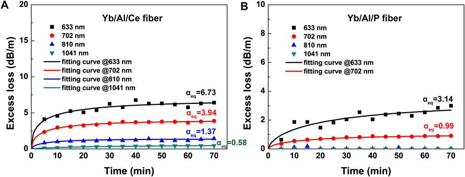
FIGURE 6. PD excess losses and fitting curves at 633 nm, 702 nm, 810 nm, and 1,041 nm of (A) Yb/Al/Ce co-doped fiber and (B) Yb/Al/P co-doped fiber.
4.2 Laser performances of Yb/Al/Ce and Yb/Al/P fibers
For the laser performances of two fibers, we measured the laser efficiencies, the TMI thresholds and output laser spectra in co-pumped, counter-pumped, and bidirectional pumping amplifiers. For a start, the laser performances of Yb/Al/Ce and Yb/Al/P fibers were verified in co-pumped amplifier and depicted in Figure 7. The output power as a function of pump power of Yb/Al/Ce and Yb/Al/P fibers were recorded and the results were shown in Figures 7A, C, respectively. The maximum output powers of Yb/Al/Ce and Yb/Al/P fibers in co-pumped amplifier were 1,803 W and 1,934 W, with the slope efficiencies of ∼78.9% and 81.7%, respectively. From the time- and frequency-domain signals as illustrated in Figures 7B, D, there were obvious fluctuations at the output power of 1803 W in Figure 7B and at the output power of 1,934 W in Figure 7D. The fluctuations in time- and frequency-domain signals indicated the onsets of TMI. Thus, we considered that the TMI thresholds of Yb/Al/Ce and Yb/Al/P fibers in co-pumped amplifier were 1,803 W and 1,934 W, respectively. Meanwhile, the further power scaling was limited by TMI effect.
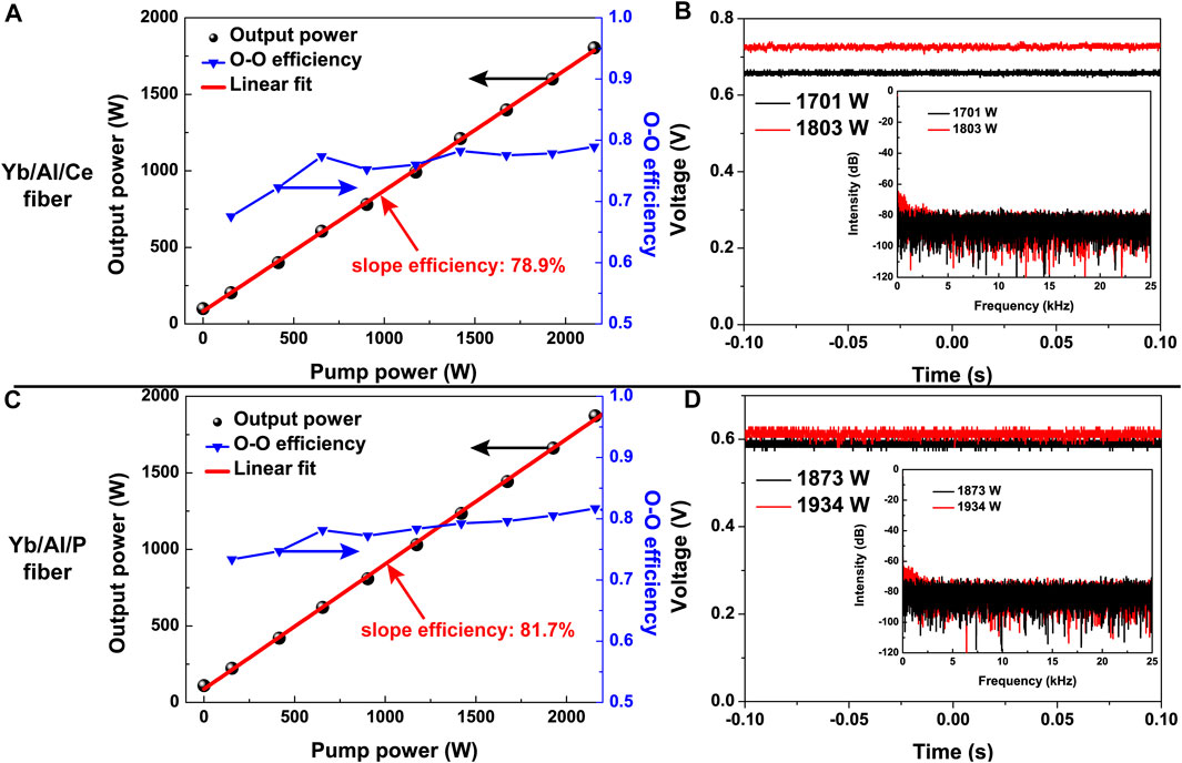
FIGURE 7. Laser performances in co-pumped amplifier. Yb/Al/Ce fiber: (A) output power and O-O efficiency dependence on the pump power; (B) time- and frequency-domain signals. Yb/Al/P fiber: (C) output power and O-O efficiency dependence on the pump power; (D) time- and frequency-domain signals.
Then, the laser performances of Yb/Al/Ce and Yb/Al/P fibers were verified in counter-pumped amplifier and described in Figure 8. The output powers of Yb/Al/Ce and Yb/Al/P fibers continuously increased to 2434 W and 3314 W without power rollover and the slope efficiencies were linearly fitted to ∼81.5% and 84.6%, as shown in Figures 8A, C, respectively. Furthermore, the time- and frequency-domain spectra were also observed by oscilloscope and there were obvious fluctuations at the output power of 2,434 W in Figure 8B and at the output power of 3,314 W in Figure 8D, respectively. Thus, we considered that the TMI thresholds of Yb/Al/Ce and Yb/Al/P fibers in counter-pumped amplifier were 2,434 W and 3,314 W, respectively. Meanwhile, the further power scaling was limited by TMI effect.
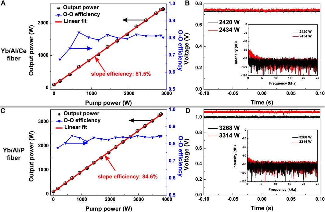
FIGURE 8. Laser performances in counter-pumped amplifier. Yb/Al/Ce fiber: (A) output power and O-O efficiency dependence on the pump power; (B) time- and frequency-domain signals. Yb/Al/P fiber: (C) output power and O-O efficiency dependence on the pump power; (D) time- and frequency-domain signals.
Finally, the output laser performances of Yb/Al/Ce and Yb/Al/P fibers with bidirectional pump were measured and recorded, as exhibited in Figure 9. The output powers of two fibers as a function of pump powers were depicted in Figures 9A, D, respectively. By continuously increasing the pump powers from the bidirectional 976-nm LDs, the output powers of Yb/Al/Ce and Yb/Al/P fibers enhanced to 2846 W and 3536 W, which the slope efficiencies were linearly fitted to ∼80.0% and ∼84.0%, respectively. Meanwhile, the beam quality M2 factors of Yb/Al/Ce and Yb/Al/P fibers at the maximum output powers were measured to be 1.42 and 1.45, respectively. From the Figures 9B, E, the signal lasers of Yb/Al/Ce and Yb/Al/P fibers were both centered at the wavelength of ∼1,080 nm, and the full width at half maximum increased to ∼3 nm of 2,846 W and ∼4 nm of 3,536 W, respectively. Simultaneously, there were Raman Stokes light in the optical spectra. The Stokes intensity was ∼44 dB below that of signal laser of Yb/Al/Ce fiber, while the intensity was ∼41 dB below that of signal laser of Yb/Al/P fiber. Thus, further power scaling was not pursued to avoid the exponential increase of the Raman Stokes light. In addition, the time- and frequency-domain signals of Yb/Al/Ce fiber at the output power of 2,846 W remained stable without any fluctuation, while those of Yb/Al/P fiber at the output power of 3,536 W were also stable, as described in Figures 9C, F, respectively. The results of the time- and frequency-domain signals of two fibers indicated the absence of the TMI effect.
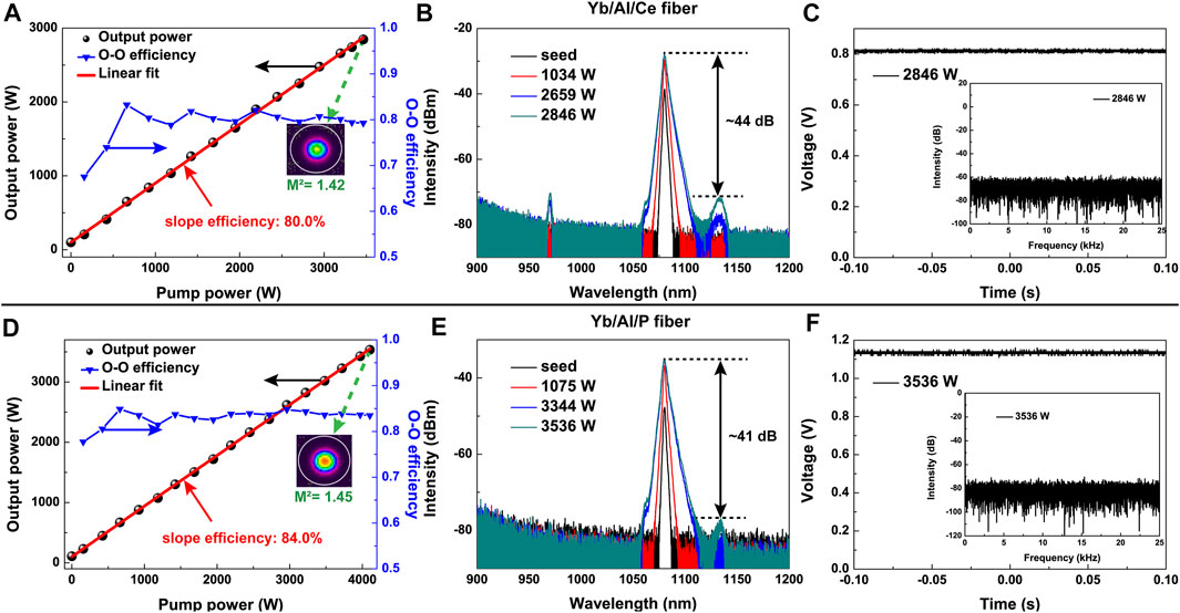
FIGURE 9. Laser performances in bidirectional pumping amplifier. Yb/Al/Ce fiber: (A) output power and O-O efficiency dependence on the pump power; (B) optical spectra at several output powers; (C) time- and frequency-domain signals. Yb/Al/P fiber: (D) output power and O-O efficiency dependence on the pump power; (E) optical spectra at several output powers; (F) time- and frequency-domain signals.
The output power stability of two fibers was monitored at ∼2.5 kW for an hour and the power values were recorded with an interval of 0.133 s. For Yb/Al/Ce co-doped fiber, the output laser power presented a power fluctuation within a range from 2,437 W to 2,506 W, ∼2.8%. For Yb/Al/P co-doped fiber, the output power was recorded from 2,488 W to 2,512 W with the power fluctuation of less 1%. It indicated that the Yb/Al/P co-doped fiber owned a better power stability.
4.3 638 nm transmittance of Yb/Al/Ce and Yb/Al/P fibers
Moreover, the 638 nm transmittances of Yb/Al/Ce and Yb/Al/P co-doped fibers were measured and compared. The experimental setup of the 638 nm transmittance was depicted in Figure 10A. 30 mW 638 nm single-mode laser was injected to two fibers by MFA. After stripped by CLS, the remanent laser was received by a milliwatt-level PM. The input end was kept unchanged and the active fiber was cut off from the output end to measure the output power at a different position. To avoid the influence of splicing loss, the output power of 638 nm laser injected in 1 cm Yb-doped fiber was measured as the initial injection power. The measured results were depicted in Figure 10B. The transmittance of Yb/Al/Ce co-doped fiber presented a rapid declining trend and the transmittance in the position of 20 m was only 30%. For Yb/Al/P co-doped fiber, the declining trend was slow and the transmittance was still up to 84% in the position of 20 m. The transmittance results demonstrated that there was more seriously distributed PD loss along the longitudinal length of Yb/Al/Ce co-doped fiber, compared with Yb/Al/P co-doped fiber.
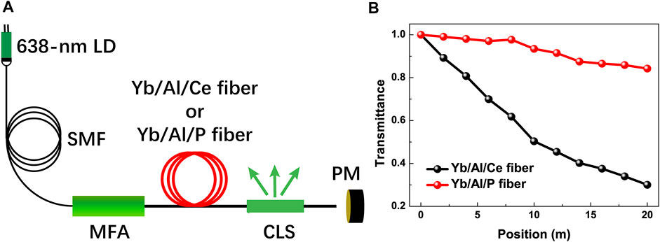
FIGURE 10. (A) Schematic diagram of the experimental setup for 638 nm transmittance measurement; (B) the measured results of the 638 nm transmittance of Yb/Al/Ce and Yb/Al/P co-doped fibers.
The aforementioned experimental results were all measured by the same setups and conditions, which ensured the credibility of the contrast experiment. Thus, we considered that the PD resistance of Yb/Al/P co-doped fiber was superior to that of Yb/Al/Ce co-doped fiber, and meanwhile the TMI thresholds and laser efficiencies of Yb/Al/P co-doped fiber in co-pumped and counter-pumped amplifiers were higher than those of Yb/Al/Ce co-doped fiber. Concretely, the excess losses of Yb/Al/Ce and Yb/Al/P fibers at 702 nm were 3.94 dB/m and 0.99 dB/m, respectively. The TMI thresholds of Yb/Al/Ce and Yb/Al/P fibers in co-pumped amplifier were 1,803 W and 1,934 W, while they were 2,434 W and 3,314 W in counter-pumped amplifier, respectively. Meanwhile, by replacing Yb/Al/Ce co-doped fiber with Yb/Al/P co-doped fiber, the slope efficiency of the signal laser was also enhanced by ∼4%. Moreover, the 638 nm transmittance confirmed that there was lower PD loss in the Yb/Al/P co-doped fiber.
In our experiment, most of parameters of two fibers were remained the same, entailing core and inner cladding diameters, core NA, pump absorption, and fiber length. Thus, the core composition became the key point for reducing the PD loss, and further suppressing the TMI effect. Meanwhile, thanks to the superior PD resistance, the TMI thresholds of Yb/Al/P co-doped fiber were higher than those of Yb/Al/Ce co-doped fiber under co-pumped and counter-pumped schemes. For Yb/Al/Ce co-doped fiber, Ce had different valence states, Ce3+/Ce4+. Through their valence-state transition, both electrons and holes related to color centers could be trapped to suppress PD effect [48]. The suppression of PD effect would mitigate the TMI effect. However, Ce-doping would introduce new heat sources to Yb-doped fiber lasers [49].
For Yb/Al/P co-doped fiber, it would effectively inhibit the generation of aluminum oxygen hole centers (Al-OHCs) and Oxygen Deficiency Centers (ODCs) by forming [AlPO4] structure [39]. Meanwhile, this structure would shift the charge-transfer band to a shorter wavelength region. Thus, Yb/Al/P co-doped fiber would present low PD sensitivity, which was beneficial for mitigating the TMI effect. Additionally, when the value of
5 Conclusion
In summary, we reported on an experimental comparison of the core-composition difference. Based on MCVD process combined with SDT, Yb/Al/Ce and Yb/Al/P co-doped fibers were fabricated, whose parameters were almost the same. Firstly, the PD-induced excess loss of Yb/Al/Ce and Yb/Al/P co-doped fibers were 3.94 dB/m and 0.99 dB/m at 702 nm, which indicated the superior PD resistance of Yb/Al/P fiber, Then, a bidirectional pumping fiber amplifier was constructed to verify the impact of PD on laser performance. The TMI thresholds of Yb/Al/P co-doped fiber were higher than those of Yb/Al/Ce co-doped fiber in co-pumped and counter-pumped schemes. The slope efficiency of Yb/Al/P co-doped fiber in bidirectional scheme was enhanced by 4%. In addition, the results of 638 nm transmittance manifested the lower PD loss of Yb/Al/P co-doped fiber. These experimental results could provide a good reference for realizing high-power fiber lasers.
Data availability statement
The original contributions presented in the study are included in the article/supplementary material, further inquiries can be directed to the corresponding author.
Author contributions
ZZ and YX proposed the idea. ZZ and YL performed the experiments. ZZ wrote the original manuscript. YX, HL, JP, ND, and JL revised the manuscript. All authors contributed to the article and approved the submitted version. JL and YX supervised the project.
Funding
This work is supported by National Natural Science Foundation of China under Grant nos. 61975061 and 61905080.
Acknowledgments
The authors wish to thank Xianfeng Lin and Anjun Zhang for their help during the experiment and thank Changjin Laser Ltd. for providing fibers. The authors also thank the Analytical and Testing Centre at the HUST for performing elemental characterization of fiber samples.
Conflict of interest
The authors declare that the research was conducted in the absence of any commercial or financial relationships that could be construed as a potential conflict of interest.
Publisher’s note
All claims expressed in this article are solely those of the authors and do not necessarily represent those of their affiliated organizations, or those of the publisher, the editors and the reviewers. Any product that may be evaluated in this article, or claim that may be made by its manufacturer, is not guaranteed or endorsed by the publisher.
References
1. Richardson DJ, Nilsson J, Clarkson WA. High power fiber lasers: Current status and future perspectives [invited]. J Opt Soc Am B (2010) 27(11):B63. doi:10.1364/josab.27.000b63
2. Jauregui C, Limpert J, Tünnermann A. High-power fibre lasers. Nat Photon (2013) 7(11):861–7. doi:10.1038/nphoton.2013.273
3. Codemard C, Zervas MN, Codemard CA. High power fiber lasers: A review. IEEE J Sel Top QUANTUM Electron (2014) 20:219–41. doi:10.1109/jstqe.2014.2321279
4. Kalisky O. The status of high-power lasers and their applications in the battlefield. Opt Eng (2010) 49(9):091003. doi:10.1117/1.3484954
5. Zhao K, Wang H, Yan J, Shen H. Welding fused silica glass by picosecond pulsed laser with low numerical aperture. J Micro Nano-manufacturing (2019) 7(4):1–8. doi:10.1115/1.4045467
6. Shiner B. The impact of fiber laser Technology on the world wide material processing market. AF2J. (2013) 1. doi:10.1364/CLEO_AT.2013.AF2J.1
7. Jauregui C, Eidam T, Schimpf DN, Limpert J, Tünnermann A. Derivation of Raman treshold formulas for CW double-clad fiber amplifiers. Opt Express (2009) 17(10):8476–90. doi:10.1364/oe.17.008476
8. Tao R, Xiao H, Zhang H, Leng J, Wang X, Zhou P, et al. Dynamic characteristics of stimulated Raman scattering in high power fiber amplifiers in the presence of mode instabilities. Opt Express (2018) 26(19):25098. doi:10.1364/oe.26.025098
9. Hu Q, Zhao X, Tian X, Wang M, Wang Z, Xu X. Raman suppression in high-power fiber laser oscillator by long period fiber grating. Results Phys (2021) 26:104460. doi:10.1016/j.rinp.2021.104460
10. Hu Q, Zhao X, Tian X, Li H, Wang M, Wang Z, et al. Raman suppression in 5 kW fiber amplifier using long period fiber grating fabricated by CO 2 laser. Opt Laser Technol (2022) 145:107484. doi:10.1016/j.optlastec.2021.107484
11. Eidam T, Wirth C, Jauregui C, Stutzki F, Jansen F, Otto H-J, et al. Experimental observations of the threshold-like onset of mode instabilities in high power fiber amplifiers. Opt Express (2011) 19(14):13218. doi:10.1364/oe.19.013218
12. Stutzki F, Otto H-J, Jansen F, Gaida C, Jauregui C, Limpert J, et al. High-speed modal decomposition of mode instabilities in high-power fiber lasers. Opt Lett (2011) 36(23):4572. doi:10.1364/ol.36.004572
13. Jauregui C, Eidam T, Otto H-J, Stutzki F, Jansen F, Limpert J, et al. Temperature-induced index gratings and their impact on mode instabilities in high-power fiber laser systems. Opt Express (2012) 20(1):440. doi:10.1364/oe.20.000440
14. Otto H-J, Stutzki F, Jansen F, Eidam T, Jauregui C, Limpert J, et al. Temporal dynamics of mode instabilities in high-power fiber lasers and amplifiers. Opt Express (2012) 20(14):15710. doi:10.1364/oe.20.015710
15. Otto HJ, Jauregui C, Eidam T, Stutzki F, Jansen F, Limpert J, et al. Dynamics and origin of mode instabilities in high power fiber laser amplifiers. CLEO Sci Innov Cleo_si (2012) 20(12):10180–92. doi:10.1364/CLEO_SI.2012.CF2N.7
16. Jauregui C, Eidam T, Otto H-J, Jansen F, Stutzki F, Limpert J, et al. On the thermal origin of mode instabilities in high power fiber lasers Fiber Lasers IX Technol. Syst Appl (2012) 8237:82370D.
17. Dong L. Stimulated thermal Rayleigh scattering in optical fibers. Opt Express (2013) 9(6):2365–70. doi:10.1364/OE.21.002642
18. Jauregui-Misas C, Stihler C, Tünnermann A, Limpert J. Origin and evolution of phase-shifts in high-power fiber laser systems: Detailed insights into TMI. SPIE (2019) 10897:10897043. doi:10.1117/12.2508854
19. Zervas MN. Transverse-modal-instability gain in high power fiber amplifiers: Effect of the perturbation relative phase. APL Photon (2019) 4(2):022802. doi:10.1063/1.5050523
20. Jauregui C, Stihler C, Limpert J. Transverse mode instability. Adv Opt. Photon (2020) 12(2):429–84. doi:10.1364/aop.385184
21. Ye C, Petit L, Koponen JJ, Hu I, Galvanauskas A. Short-term and long-term stability in lasers and amplifiers. IEEE J Sel Top Quan Electron. (2014) 20(5):1. doi:10.1109/JSTQE.2014.2310657
22. Manek-Hönninger I, Boullet J, Cardinal T, Guillen F, Podgorski M, Ermeneux S, et al. Photodarkening and photobleaching of an ytterbium-doped silica double-clad LMA fiber. Opt Infobase Conf Pap (2007) 15(4):1606–11. doi:10.1364/oe.15.001606
23. Montiel I Ponsoda JJ, Söderlund MJ, Koplow JP, Koponen JJ, Honkanen S. Photodarkening-induced increase of fiber temperature. Appl Opt (2010) 49(22):4139–43. doi:10.1364/ao.49.004139
24. Kong L, Leng J, Zhou P, Jiang Z. Thermally induced mode loss evolution in the coiled ytterbium doped large mode area fiber. Opt Express (2017) 25(19):23437. doi:10.1364/oe.25.023437
25. Feng Y, Zhang BM, Nilsson J. Photodarkening-induced phase distortions and their effects in single-channel and coherently combined Yb-doped fiber chirped pulse amplification systems. J Light Technol (2018) 36(23):5521–7. doi:10.1109/jlt.2018.2874086
26. Otto H-J, Modsching N, Jauregui C, Limpert J, Tünnermann A. Impact of photodarkening on the mode instability threshold. Opt Express (2015) 23(12):15265. doi:10.1364/oe.23.015265
27. Ward B. Theory and modeling of photodarkening-induced quasi static degradation in fiber amplifiers. Opt Express (2016) 24(4):3488. doi:10.1364/oe.24.003488
28. Bobkov KK, Bubnov MM, Aleshkina SS, Likhachev ME. Long-term mode shape degradation in large mode area Yb-doped pulsed fiber amplifiers. Laser Phys Lett (2017) 14(1):015102. doi:10.1088/1612-202x/14/1/015102
29. Mattsson KE. Low photo darkening single mode RMO fiber. Opt Express (2009) 17(20):17855. doi:10.1364/oe.17.017855
30. Leich M, Röpke U, Jetschke S, Unger S, Reichel V, Kirchhof J. Non-isothermal bleaching of photodarkened Yb-doped fibers. Opt Express (2009) 17(15):12588. doi:10.1364/oe.17.012588
31. Cao R, Lin X, Chen Y, Cheng Y, Wang Y, Xing Y, et al. 532 nm pump induced photo-darkening inhibition and photo-bleaching in high power Yb-doped fiber amplifiers. Opt Express (2019) 27(19):26523. doi:10.1364/oe.27.026523
32. Jasapara J, Andrejco M, DiGiovanni D, Windeler R. Effect of heat and H2 gas on the photo-darkening of Yb +3 fibers. In: Conf. Lasers Electro-Optics 2006 Quantum Electron. Laser Sci. Conf. CLEO/QELS; 21-26 May 2006; Long Beach, CA, USA (2006). p. 2006 2–3.
33. Yoo S, Basu C, Boyland AJ, Sones C, Nilsson J, Sahu JK, et al. Photodarkening in Yb-doped aluminosilicate fibers induced by 488 nm irradiation. Opt Lett (2008) 33(11):1626. doi:10.1364/ol.32.001626
34. Engholm M, Norin L. Reduction of photodarkening in Yb/Al-doped fiber lasers. Fiber Lasers V Technol Syst Appl (2008) 6873:68731E. doi:10.1117/12.763218
35. Cao R, Chen G, Chen Y, Zhang Z, Lin X, Dai B, et al. Effective suppression of the photodarkening effect in high-power Yb-doped fiber amplifiers by H 2 loading. Photon Res (2020) 8(3):288. doi:10.1364/prj.381208
36. Zhao N, Liu Y, Li M, Li J, Peng J, Yang L, et al. Mitigation of photodarkening effect in Yb-doped fiber through Na^+ ions doping. Opt Express (2017) 25(15):18191. doi:10.1364/oe.25.018191
37. Engholm M, Jelger P, Laurell F, Norin L. Improved photodarkening resistivity in ytterbium-doped fiber lasers by cerium codoping. Opt Lett (2009) 34(8):1285. doi:10.1364/ol.34.001285
38. Jetschke S, Unger S, Schwuchow A, Leich M, Kirchhof J. Efficient Yb laser fibers with low photodarkening by optimization of the core composition. Opt Express (2008) 16(20):15540. doi:10.1364/oe.16.015540
39. Liu S, Peng K, Zhan H, Ni L, Wang X, Wang Y, et al. 3 kW 20/400 Yb-doped aluminophosphosilicate fiber with high stability. IEEE Photon J (2018) 10(5):1–8. doi:10.1109/jphot.2018.2860584
40. Li Y, Liu S, Zhan H, Peng K, Sun S, Jiang J, et al. Fiber design and fabrication of Yb/Ce codoped aluminosilicate laser fiber with high laser stability. IEEE Photon J (2018) 10(4):1–8. doi:10.1109/jphot.2018.2853665
41. Jauregui C, Stutzki F, Tünnermann A, Limpert J. Thermal analysis of Yb-doped high-power fiber amplifiers with Al:P co-doped cores. Opt Express (2018) 26(6):7614. doi:10.1364/oe.26.007614
42. Townsend JE, Poole SB, Payne DN. Solution-doping technique for fabrication of rare-earth-doped optical fibres. Electron Lett (1987) 23(7):329–31. doi:10.1049/el:19870244
43. Matejec V, Kasik I, Berkova D, Hayer M, Chomat M, Berka Z, et al. Properties of optical fiber performs prepared by inner coating of substrate tubes. Ceram Silik (2001) 45(2):62–9.
44. Wang Y, Gao C, Tang X, Zhan H, Peng K, Ni L, et al. 30/900 Yb-doped aluminophosphosilicate fiber presenting 6.85-kW laser output pumped with commercial 976-nm laser diodes. J Light Technol (2018) 36(16):3396–402. doi:10.1109/jlt.2018.2823504
45. Saitoh K, Tsuchida Y, Koshiba M. Design of effectively single-mode leakage channel fibers with large mode area and low bending loss. IEICE Electron Express (2009) 6(7):412–7. doi:10.1587/elex.6.412
46. Wang X, Lou S, Lu W, Sheng X, Zhao T, Hua P. Bend resistant large mode area fiber with multi-trench in the core. IEEE J Sel Top Quan Electron. (2016) 22(2):117–24. doi:10.1109/jstqe.2015.2461456
47. Jetschke S, Röpke U. Power-law dependence of the photodarkening rate constant on the inversion in Yb doped fibers. Opt Lett (2009) 34(1):109–11. doi:10.1364/ol.34.000109
48. Jetschke S, Unger S, Schwuchow A, Leich M, Jäger M. Role of Ce in Yb/Al laser fibers: Prevention of photodarkening and thermal effects. Opt Express (2016) 24(12):13009. doi:10.1364/oe.24.013009
Keywords: Yb-doped fiber, core composition, photodarkening, transverse mode instability, stimulated Raman scattering
Citation: Zhang Z, Luo Y, Xing Y, Li H, Peng J, Dai N and Li J (2023) Experimental comparison of Yb/Al/Ce and Yb/Al/P co-doped fibers on the suppression of transverse mode instability. Front. Phys. 11:1124491. doi: 10.3389/fphy.2023.1124491
Received: 15 December 2022; Accepted: 09 January 2023;
Published: 18 January 2023.
Edited by:
Shuo Liu, Hebei University of Technology, ChinaReviewed by:
Xinyang Su, Beijing Jiaotong University, ChinaLei Gao, Chongqing University, China
Zhaohong Liu, Hebei University of Technology, China
Copyright © 2023 Zhang, Luo, Xing, Li, Peng, Dai and Li. This is an open-access article distributed under the terms of the Creative Commons Attribution License (CC BY). The use, distribution or reproduction in other forums is permitted, provided the original author(s) and the copyright owner(s) are credited and that the original publication in this journal is cited, in accordance with accepted academic practice. No use, distribution or reproduction is permitted which does not comply with these terms.
*Correspondence: Yingbin Xing, anN4eWIxMjMyMDA4QDEyNi5jb20=
 Zhilun Zhang
 Yonghui Luo
