
95% of researchers rate our articles as excellent or good
Learn more about the work of our research integrity team to safeguard the quality of each article we publish.
Find out more
ORIGINAL RESEARCH article
Front. Phys. , 13 February 2023
Sec. Space Physics
Volume 11 - 2023 | https://doi.org/10.3389/fphy.2023.1103159
This article is part of the Research Topic Advances on Upper-Atmosphere Characterization for Geodetic Space Weather Research and Applications View all 6 articles
 Danning Zhao1,2
 Yu Lei3*
Wideband GNSS signals suffer signal distortions such as waveform deformations and correlation peak reduction when traverse the ionosphere. Basing on the standard model of the ionosphere, we first demonstrate a modified ionosphere model to capture the ionosphere dispersion effects on wideband signals. We decompose the first-order ionosphere model into Taylor series. By using the first three terms of Taylor series, it is possible to account for all frequency components of wideband signals rather than treating them as single tone. We then make an analysis of the ionosphere dispersion effects on wideband GNSS signal tracking. It is revealed that the ionosphere dispersion degrades correlation peak results and shifts carrier-phase in the phase locked loop (PLL) output but dose not cause an additional delay for code measurements. Furthermore, we carry out a simulation for evaluating the ionosphere dispersion effects on tracking of various new generation wideband GNSS signals such as Galileo E5 AltBOC(15, 10) signals and BDS B3 BOC(15, 2.5) signals during ionosphere quietness and activities. The results show that the wider the bandwidth and the greater the total electron content (TEC) values, the more dramatic the ionosphere effects are. The Galileo E5 AltBOC(15, 10) signals are most affected among various wideband GNSS signals. For AltBOC(15, 10) signal tracking the correlation power loss is around 0.1 dB and the carrier-phase change is about 20° caused by the dispersion in quiet ionosphere case, and increases up to 0.35 dB and 33° during ionosphere activities, respectively.
Wideband signals show promise for GPS modernization and Galileo and BDS development since they provide sharper correlation peaks and therefore more accuracy. For example, the Galileo E5 signal occupies the frequency band from 1,164 MHz to 1215 MHz over 25 times the double-sided bandwidth of the GPS L1 C/A code. However, different frequency components in the wideband spectrum suffer different signal delay owing to refraction when traveling through the upper atmosphere, since the ionosphere is dispersive [1].
The ionosphere delay is the major and most variable source of ranging error for global navigation satellite system (GNSS) positioning, navigation and timing (PNT) services [2]. Generally, single-frequency receivers employ empirical model such as the NeQuick and Klobuchar models to correct the ionosphere delay [3, 4], while dual-frequency receivers combine dual-frequency measurements to compensate for the first-order ionosphere delay [5]. These methods assume each incoming signal to comprise a single-frequency tone represented by the center frequency and thus only evaluate the center frequency ionosphere delay to replace the total group delay. This assumption is effective for narrowband GNSS signals, e.g., GPS L1 C/A code, whose double-sided bandwidth is 2 MHz. The ionosphere delay variations with frequency band become larger as the band gets wider. Therefore, the simplification that the incoming signal is a single frequency tone is ineffective for wideband signals and different ionosphere delay should no longer be ignored as in the narrowband GNSS signal case [6–8]. This motivates us to upgrade the ionosphere model to take into consideration all frequency components of wideband signals rather than regarding them as a single-frequency tone.
The ionosphere dispersion effects on wideband GNSS signals were first studied by Christie et al. (1996) in [9]. Gao et al. (2007) in [6] developed a method to calculate the ionosphere delay of wideband signals and simulated the ionosphere effects on wideband GNSS signals. It was found that the ionosphere dispersion leads to time-domain signals distortions and correlation peak asymmetry. Liu et al. (2011) in [1] derived the dual sideband model of ideal band-limited BOC modulated signals and then analzyed the dispersive effect of ionosphere on BOC signals. Reference [7] and [9–14] provided the methods for compensation of ionosphere dispersion effects. It was reported that the ionosphere dispersion effects can be mitigated by the corresponding design and implementation.
It is the asymmetry and non-linear phase response to the dispersive ionosphere which causes wideband signal deformations [7]. This work will focus on analyzing the impacts of ionosphere dispersion on wideband GNSS signal tracking. We first develop a model to modify the first-order ionosphere total group delay of wideband signals. Secondly, we provide the formula for analyzing the influences of ionosphere dispersion on power loss of the correlation peak, code tracking bias and carrier-phase shifts in the phase locked loop (PLL) output. It is demonstrated from the theoretical analysis that the ionosphere dispersion does not cause any additional delay for code measurements but shifts the carrier-phase and brings correlation power loss. Furthermore, we evaluate the dispersion effects on the correlation peak and carrier-phase offset for wideband GNSS signal tracking such as Galileo E5 AltBOC(15, 10) and BDS B3 BOC(15, 2,5) signals during normal ionosphere conditions and ionosphere storms through computer simulation, and give the analytical results from the simulation.
The ionosphere is dispersive; the refractive index of the ionosphere depends on signal frequency. Higher frequency elements of signals propagate faster than lower frequency ones. Different frequency elements thus suffer different delay due to the refraction through the ionosphere. That is, low frequency elements suffer greater delay than high frequency ones. The ionospher’s frequency-dependent group delay are expressed as follows [15].
where
Because the high-order terms are relatively small and hence can be ignored, this equation can be simplified by focusing on the first term.
where
The propagation characteristics of the dispersive ionosphere can be described using linear system, in which
The
Because the center frequency of GNSS signals is very high, the coefficient is small enough when
Accordingly, the low-pass equivalent model for the phase response is written as
The group delay response to the ionosphere dispersion and corresponding low-pass equivalent model can be derived from the definitions of the group delay as follows respectively.
and
Figure 1 depicts how the group delay and phase advance vary within the band around the center frequency 1,191.795 MHz of Galileo E5 AltBOC(15, 10) signals calculated from the first-order ionosphere model. We take TEC = 100 TECU (TEC unit) for the simulation. This is a typical mid-latitude daytime and corresponds to an about 13 m delay for GPS L1 frequency users. It is shown that the ionosphere delay is neither symmetric nor linear within the frequency band. The varying ionosphere delay results in signal distortions characterized by correlation peak asymmetry and waveform deformations. In addition, the ionosphere delay variations calculated from the second-order Taylor series approximation model is displayed in Figure 1 together with the approximation error. It can be seen from Figure 1 that the delay calculated from the first-order ionosphere model and that from the approximation are close to each other and the approximation error is small enough, demonstrating the efficiency of the second-order Taylor series approximation model for calculating ionosphere delay of wideband signals.
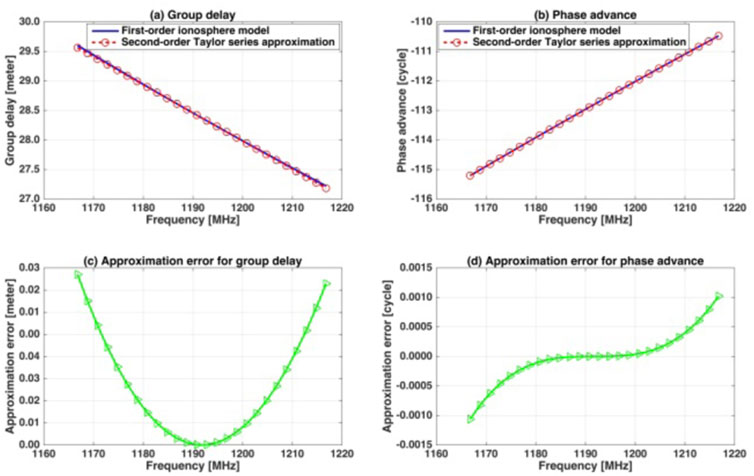
FIGURE 1. Group delay and phase advance of E5 AltBOC(15, 10) signals calculated from the conventional first-second ionosphere model and second-order Taylor series approximation model.
Since it is the asymmetry and non-linear phase response to the dispersive ionosphere that causes the wideband signal distortions, the transfer function of the dispersive ionosphere can be expressed as follows using a non-linear phase model regardless of the constant and linear terms in Eq. 7.
In this section, we will study the ionosphere dispersion effects on code and carrier-phase tracking of wideband GNSS signals.
Non-coherent early-late processing (NELP) time of arrival (TOA) estimator is described in [16] and shown in Figure 2. In NELP, the carrier-phase of the received signal is assumed unknown, so the processing is independent of carrier-phase. The ionosphere is moved to signal baseband to facilitate the dispersion effect analysis, as shown in Figure 2.
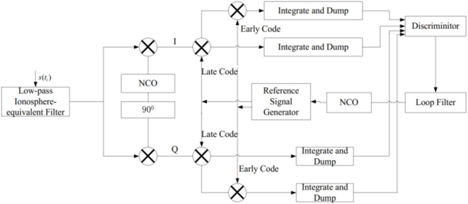
FIGURE 2. Non-coherent early-late processing (NELP) TOA estimator.
The received signal
with the code signal
According to Figure 2, the steady-state code delay can be estimated from an early-minus-late envelope discriminator of the non-coherent double-sided band receiver as given by Eq. 12 below.
where
The wideband ionosphere, however, degrades the correlation results that is derived from Figure 2 as
with the code correlation function free of the ionosphere dispersion within frequency band
and the output of a prompt correlator
The dispersive ionosphere also shifts the carrier-phase in the PLL output [16,17], as shown in Figure 3.
where the code delay
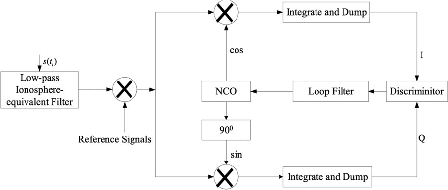
FIGURE 3. Representation of carrier-phase tracking loop.
In this section the computer simulation is carried out to examine power loss of the correlation peaks and carrier-phase shifts in the PLL output for wideband GNSS signals after passing through the ionosphere. The block diagram in Figure 4 reveals the basic steps undertaken in the simulation. The simulation parameters (TEC, center frequency and double-sided bandwidth of signals) are first selected. The signals through the low-pass ionosphere-equivalent filter are then tracked and processed.
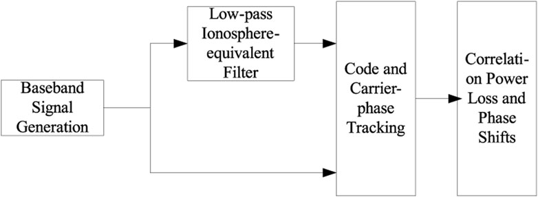
FIGURE 4. Schematic of computer simulation.
New generation GNSS signals, e.g., BDS B3 BOC(15, 2.5), GPS L1 BOC(10, 5) and Galileo E5 AltBOC(15, 10), are taken as examples to evaluate the ionosphere dispersion on wideband signals tracking. The selected center frequency and double-sided bandwidth of these signals for this simulation are listed in Table 1. Figures 5, 6 show the power loss of the correlation peaks and carrier-phase offsets for these wideband GNSS signal tracking under various ionosphere conditions, respectively. It can seen from Figure 5 that the correlation power of the correlation peaks for BOC(10, 5), BOC(15, 2.5) and BOC(14, 2) signal tracking can be ignorable even in ionosphere activity conditions, whereas the wideband ionosphere can introduce the relative large correlation power for AltBOC(15, 10) signal tracking, especially during ionosphere activity. As for carrier-phase shifts in the PLL output, the phase changes for these signal tracking are less than 100 in the quiet ionosphere case (TEC = 100 TECU) as observed in Figure 6, but increase linearly with TEC, specially up to 10°, 26°, 12° and 33° for BOC(10, 5), BOC(15, 2.5), BOC(14, 2) and AltBOC(15, 10) signal tracking, respectively, when ionosphere storms occur, i.e., TEC = 500 TECU. The correlation power loss and phase offsets for AltBOC(15, 10) signal tracking is shown in Figure 7 for different signal bandwidths and TEC values. It can be observed that the wider the bandwidth is, the greater the correlation power loss and phase change are for same TEC values, demonstrating unique ionosphere dispersion effects on wideband GNSS signals.
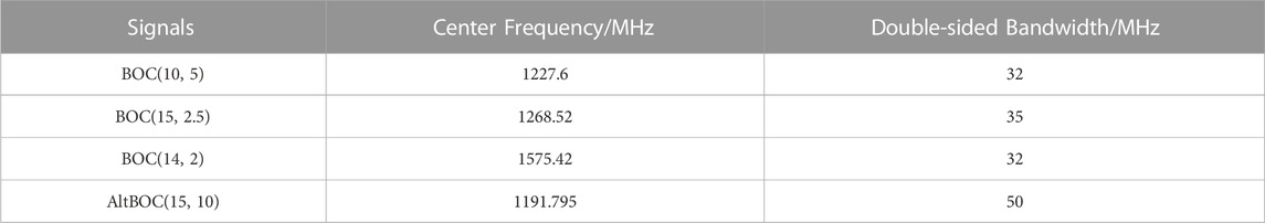
TABLE 1. Center frequency and double-sided bandwidth of the new generation GNSS signals.
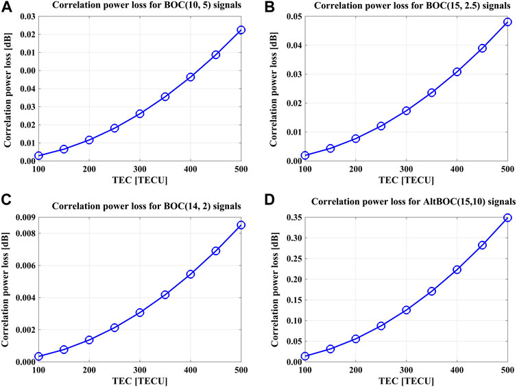
FIGURE 5. Power loss of the correlation peaks for different TEC values.

FIGURE 6. Carrier-phase offsets for different TEC values.
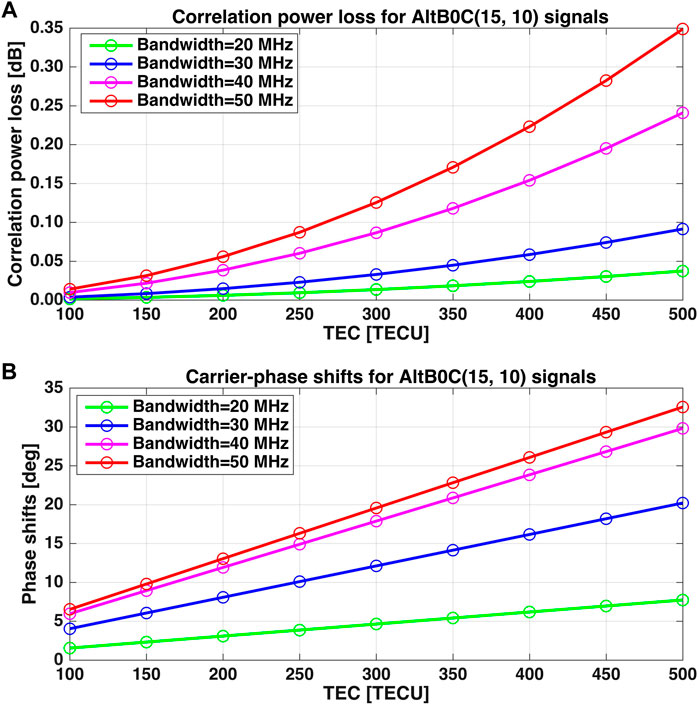
FIGURE 7. Correlation power loss and phase offsets for different bandwidths.
This work illustrates the effects of the ionosphere dispersion on tracking of various wideband GNSS signals such as Galileo E5 AltBOC(15, 10) signals and BDS B3 BOC(15, 2.5) signals during quiet ionosphere conditions and ionosphere activities. In addition to the carrier-phase advance and code delay, the dispersive ionosphere brings extra effects on wideband signals. The ionosphere dispersion would cause the correlation power loss and carrier-phase offsets in the PLL output for wideband GNSS signal tracking, but would not result in an additional delay in the estimated code delay, if techniques for ionosphere dispersion compensation in receivers were not implemented. The greater the TEC values and the wider the bandwidth, the more dramatic the ionosphere dispersion effects are. The simulation results show that due to the ionosphere the Galileo E5 AltBOC(15, 10) signals at the 1,191.795 MHz center frequency with the 50 MHz bandwidth suffer about 0.1 dB correlation power loss and about 20° phase change in quiet ionosphere case, and the correlation peak reduction and phase change increase dramatically to 0.35 dB and 33° during ionosphere activities, respectively. For the BDS B3 BOC(15, 2.5) signals centered at 1,268.52 MHz with the 35 MHz bandwidth the correlation peak reduction resulted from the ionosphere dispersion is ignorable even in ionosphere storm conditions, but typical TEC results in a phase shift of around 15°. It is suggested that techniques for compensation of the ionosphere dispersion effects such as all-pass filter should be utilized before wideband signals are acquired and tracked to avoid correlation peak reduction and phase change.
It should be noted that we studied on the ionosphere dispersion effects only through a simulation rather than use of real-world data. Also, we only considered the first-order ionospheric terms but ignored higher-order terms. In the future we will study not only on the first-order ionospheric effects, but also on higher-order effects on wideband GNSS signals in the case of ionosphere quiet and ionosphere storms using real-world GNSS signals.
The original contributions presented in the study are included in the article/Supplementary Material, further inquiries can be directed to the corresponding author.
DZ: Data curation, software, visualization, writing-original draft, formal analysis; YL: Methodology, project administration, supervision, validation, visualization, writing-review and editing, funding acquisition.
This study was supported by the Natural Science Foundation of Shaanxi No. 2023-JC-YB-057 and 2022JM-031.
The authors declare that the research was conducted in the absence of any commercial or financial relationships that could be construed as a potential conflict of interest.
All claims expressed in this article are solely those of the authors and do not necessarily represent those of their affiliated organizations, or those of the publisher, the editors and the reviewers. Any product that may be evaluated in this article, or claim that may be made by its manufacturer, is not guaranteed or endorsed by the publisher.
1. Feng T, Kai Z, Liang C. Unambiguous tracking of BOC signals using coherent combination of dual sidebands. IEEE Commun Lett (2016) 20:1555–8. doi:10.1109/LCOMM.2016.2569520
2. Dubey S, Wahi R, Gwal AK. Ionospheric effects on GPS positioning. Adv Space Res (2006) 38:2478–84. doi:10.1016/j.asr.2005.07.030
3. Bidaine B, Lonchay M, Warnant R. Galileo single frequency ionospheric correction: Performances in terms of position. GPS solut (2013) 17:63–73. doi:10.1007/s10291-012-0261-0
4. Macalalad EP, Tsai LC, Wu J. Performance evaluation of different ionospheric models in single-frequency code-based differential GPS positioning. GPS Solut (2016) 20:173–85. doi:10.1007/s10291-014-0422-4
5. Banville S, Sieradzki R, Hoque M, Wezka K, Hadas T. On the estimation of higher-order ionospheric effects in precise point positioning. GPS Solut (2017) 21:1817–28. doi:10.1007/s10291-017-0655-0
6. Gao GX, Datta-Barua S, Walter T, Enge P. Ionosphere effects for wideband GNSS signals. In: Proceedings of the 63rd annual meeting of the institute of navigation; Cambridge, MA (2007). p. 147–55.
7. Guo N, Kou Y, Zhao Y, Yu Z, Chen Y. An all-pass filter for compensation of ionospheric dispersion effects on wideband GNSS signals. GPS Solut (2014) 18:625–37. doi:10.1007/s10291-014-0397-1
8. Pang J, Liu YX, Tang XM, Ou G. Ionosphere dispersion effects simulation for high order BOC modulated signals. J Natl Universality Defense Technol (2015) 2015:74–7. 1001-2486(2015)06-074-04.
9. Christie JR, Parkinson WB, Enge P. The effects of the ionosphere and C/A frequency on GPS signal shape: Considerations for GNSS-2. In: Proceedings of the 9th International Technical Meeting of the Satellite Division of The Institute of Navigation (ION GPS 1996); September 1996; Kansas City, MO (1996). p. 647–53.
10. Ruan H, Zhang L, Long T. Sinc interpolation based method for compensation of ionospheric dispersion effects on BOC signals with high subcarrier rate. Sci China Inf Sci (2016) 59:102311. doi:10.1007/s11432-016-5555-3
11. Guo NY, Yu ZB, Kou YH, Lu MQ. Trust-region optimization of all-pass filter for compensation of ionospheric dispersion effects on wideband GNSS signals. Adv Space Res (2020) 66:2865–72. doi:10.1016/j.asr.2019.12.014
12. Lobov EM, Lobova EO, Elsukov BA. Wideband signals dispersion distortion compensator based on digital filter banks. In: 2018 Systems of signals generating and processing in the field of on board communications. Moscow, Russia: IEEE (2018). p. 1–4. doi:10.1109/SOSG.2018.8350615
13. Yao HG, Li Z. Compensation for the ionospheric dispersion effect on spaceborne P-band full-polarimetric wideband SAR. Remote Sens Lett (2022) 13:876–87. doi:10.1080/2150704X.2022.2105665
14. Zhuo L, Zan YK. Performance analysis of autofocus algorithms for compensating ionospheric dispersion effect on spaceborne low-frequency SAR focusing. IEEE Geosci Remote S (2020) 18:331–5. doi:10.1109/LGRS.2020.2970720
15. Hoque MM, Jakowski N. Mitigation of higher order ionospheric effects on GNSS users in Europe. GPS Solut (2008) 12:87–97. doi:10.1007/s10291-007-0069-5
16. Bezt JW, Kolodziejski KR. Generalized theory of code tracking with an early-late discriminator part II: Noncoherent processing and numerical results. IEEE T Aero Elec Sys (2009) 45:1557–64. doi:10.1109/TAES.2009.5310317
Keywords: ionosphere dispersion, wideband GNSS signals, correlation power loss, carrier-phase shifts, analytic model
Citation: Zhao D and Lei Y (2023) Effects of ionosphere dispersion on wideband GNSS signals. Front. Phys. 11:1103159. doi: 10.3389/fphy.2023.1103159
Received: 20 November 2022; Accepted: 27 January 2023;
Published: 13 February 2023.
Edited by:
Andrés Calabia, Polytechnic University of Madrid, SpainReviewed by:
José Francisco Oliveira Júnior, Federal University of Alagoas, BrazilCopyright © 2023 Zhao and Lei. This is an open-access article distributed under the terms of the Creative Commons Attribution License (CC BY). The use, distribution or reproduction in other forums is permitted, provided the original author(s) and the copyright owner(s) are credited and that the original publication in this journal is cited, in accordance with accepted academic practice. No use, distribution or reproduction is permitted which does not comply with these terms.
*Correspondence: Yu Lei, bGVpeXVAeHVwdC5lZHUuY24=
Disclaimer: All claims expressed in this article are solely those of the authors and do not necessarily represent those of their affiliated organizations, or those of the publisher, the editors and the reviewers. Any product that may be evaluated in this article or claim that may be made by its manufacturer is not guaranteed or endorsed by the publisher.
Research integrity at Frontiers
Learn more about the work of our research integrity team to safeguard the quality of each article we publish.